-
PDF
axe210_xbee.pdf
XBee Module 9 Project Example 1 – Temperature and Light Sensors In this first example project a DS18B20 temperature sensor and a Light Dependant Resistor are connected to the PICAXE-18X chip. The data from these sensors is then transmitted to a second XBee unit that is connected to a computer.Unique
-
PDF
STM32_DS1307.pdf
DS1307 – 24C128 – DS18B20 – Module We are only interested in RTC-chip DS1307. We do not use memory chip 24C128 and digital thermometer IC DS18B20, and we do not use any battery on the back side of the module. We only use the
in „I2C STM32F103“ · Mikrocontroller und Digitale Elektronik ·
-
PDF
camaro_stand_alone.pdf
PD7 2 N 2,2k +5V GND5 +5V 7 k 2 N D 1 3 2 1 , 1 G S R 4 8 R3 220 I 4 1 Luefter2 0 0 0 M J1 1 1 1 DS18B20 R11 X X X DS1820 OK2 V GND + C C Brake und Getriebetemp Eingänge Wahlhebel GND GND X3A Thermistor X4A PSWITCH-N 2,7k J5 +5V +5V Gehäuselüfter kommt vom thermistor X3B 1 4 X4B PSWITCH-R R5 2 0 Brake
in „Stn1110 am atmega2560 uart probleme“ · Mikrocontroller und Digitale Elektronik ·
-
Bild
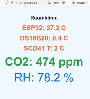
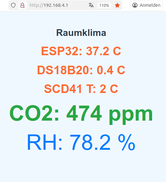
Webseiten-Screenshot einer Raumklimamessung
Raumklima ESP32: 37.2 C DS18B20: 0.4 C SCD41 T: 2 C CO2: 474 ppm RH: 78.2 %
in „Micropython Wetterstation“ · Projekte & Code · · Screenshots
-
Bild
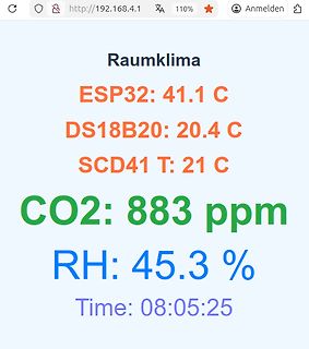
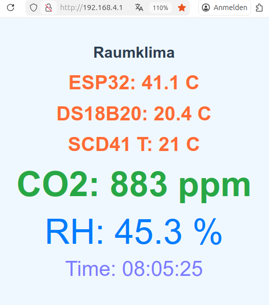
Webseiten-Screenshot einer Raumklimamessung
Raumklima ESP32: 41.1 C DS18B20: 20.4 C SCD41 T: 21 C CO2: 883 ppm RH: 45.3 % Time: 08:05:25
in „Micropython Wetterstation“ · Projekte & Code · · Screenshots
-
Bild
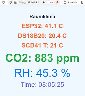
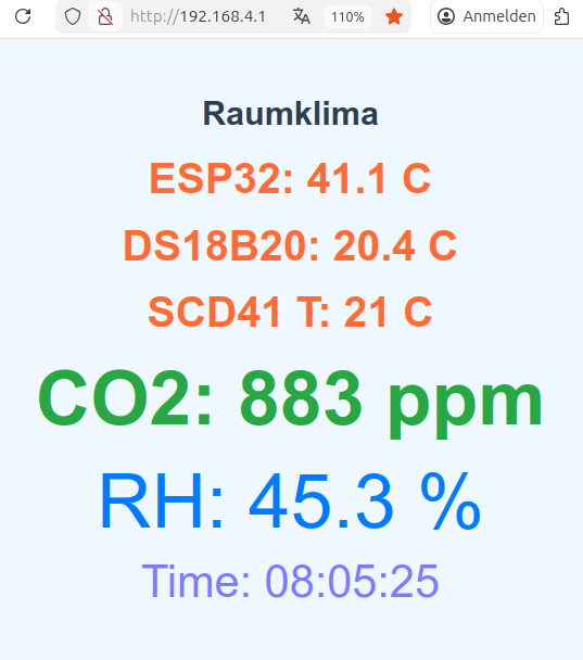
Webseite mit Raumklima-Messwerten
Raumklima ESP32: 41.1 C DS18B20: 20.4 C SCD41 T: 21 C CO2: 883 ppm RH: 45.3 % Time: 08:05:25
in „Micropython Wetterstation“ · Projekte & Code · · Screenshots
-
Bild
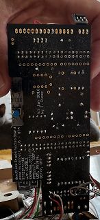
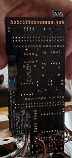
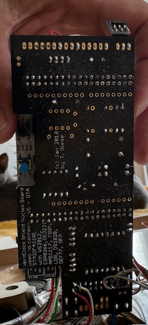
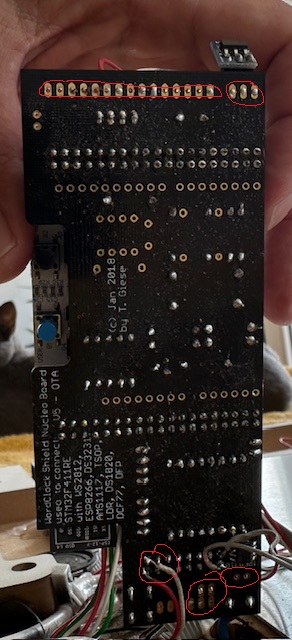
Rückseite einer Leiterplatte mit Beschriftung
(c) Jan 2018 by T. Giese used to connect: Nucleo Board U5 with WS2812B, DS3231, ESP8266, DS18B20, AMS1117, DS1820, DCF77, DFROBOT
in „WordClock mit WS2812“ · Projekte & Code · · Platinenfotos
-
Bild
Rückseite einer Hardlock Shield Nucleo Board Leiterplatte
by T. Giese Hardlock Shield Nucleo Board STM32F411RE with ESP8266, DS3231, AMS1117, TSL2561, LDR, DS18B20, DFPlayer Mini, DCF77
in „WordClock mit WS2812“ · Projekte & Code · · Platinenfotos
-
Datei
Webseite_mit_10_Zeilen.txt
SD Karte die</h3><br/> <h4>ausgelesen wird!</h4><br/> Temperatur am Verdampfer der Klimaanlage: ~ds18b20TempIn~ *C </body> </html>
in „ATMega644 hängt sich auf und resettet sich selbst, nach lesen einer SD Karte und ENC28J60“ · Mikrocontroller und Digitale Elektronik ·
-
Bild
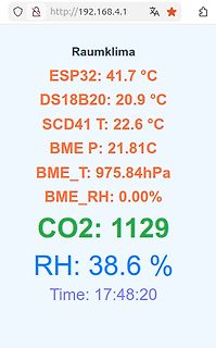
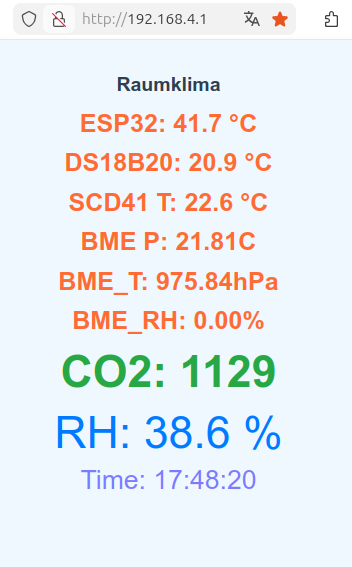
Webseiten-Screenshot mit Sensordaten zur Raumklima-Überwachung
Raumklima ESP32: 41.7 °C DS18B20: 20.9 °C SCD41 T: 22.6 °C BME P: 21.81C BME_T: 975.84hPa BME_RH: 0.00% CO2: 1129 RH: 38.6 % Time: 17:48:20
in „Micropython Wetterstation“ · Projekte & Code · · Screenshots
-
Bild
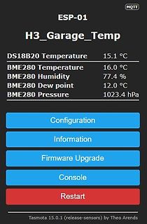
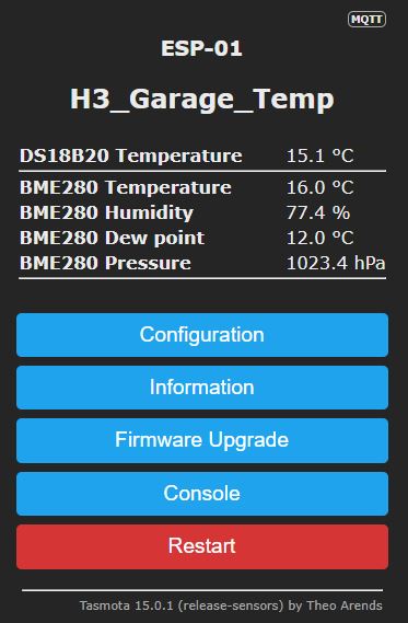
Tasmota Webinterface ESP-01 Sensordaten
MQTT ESP-01 H3_Garage_Temp DS18B20 Temperature 15.1 °C BME280 Temperature 16.0 °C BME280 Humidity 77.4 % BME280 Dew point 12.0 °C BME280 Pressure 1023.4 hPa Configuration Information Firmware Upgrade Console Restart Tasmota 15.0.1
in „Temperaturmessung mit ESP01S“ · Mikrocontroller und Digitale Elektronik · · Screenshots
-
Bild
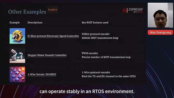
Präsentationsfolie über RMT-Features von Espressif
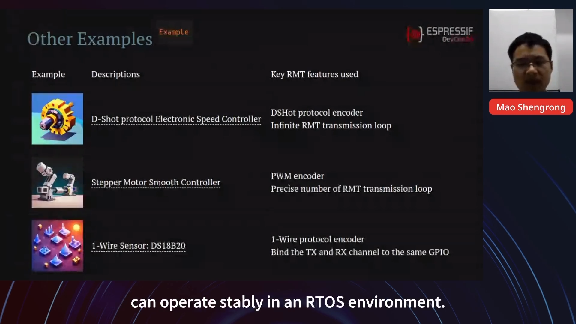
Stepper Motor Smooth Controller PWM encoder Precise number of RMT transmission loop 1-Wire Sensor: DS18B20 1-Wire protocol encoder Bind the TX and RX channel to the same GPIO can operate stablly in an RTOS environment. ESPRESSIF DevCon Mao Shengrong
in „Komponenten und Buildsystem – Espressif DevCon 2024, Tag 2“ · Mikrocontroller und Digitale Elektronik · · Screenshots
-
Bild
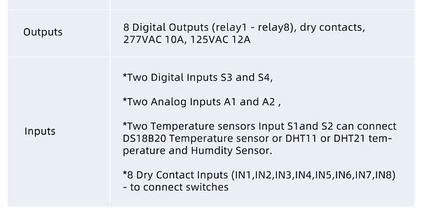
Spezifikationen von Digitalen und Analogen Ein- und Ausgängen
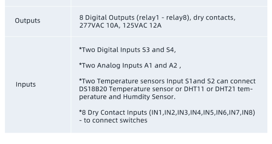
Inputs S3 and S4, *Two Analog Inputs A1 and A2 , *Two Temperature sensors Input S1and S2 can connect DS18B20 Temperature sensor or DHT11 or DHT21 temperature and Humdity Sensor. *8 Dry Contact Inputs (IN1,IN2,IN3,IN4,IN5,IN6,IN7,IN8) - to connect switches
in „AM312 am KC868-A8“ · Mikrocontroller und Digitale Elektronik · · Screenshots
-
Bild
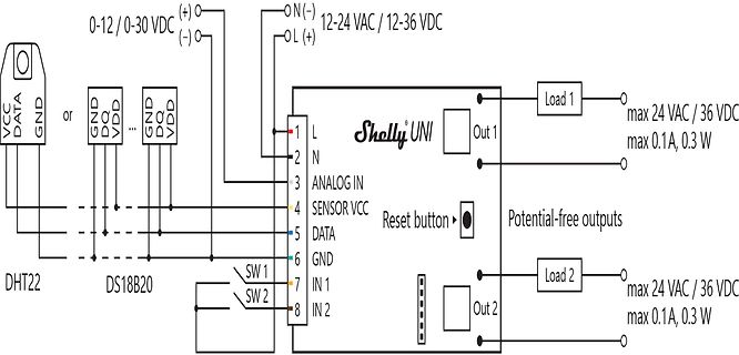
Schaltplan Shelly UNI mit Sensoranschlüssen und Lasten
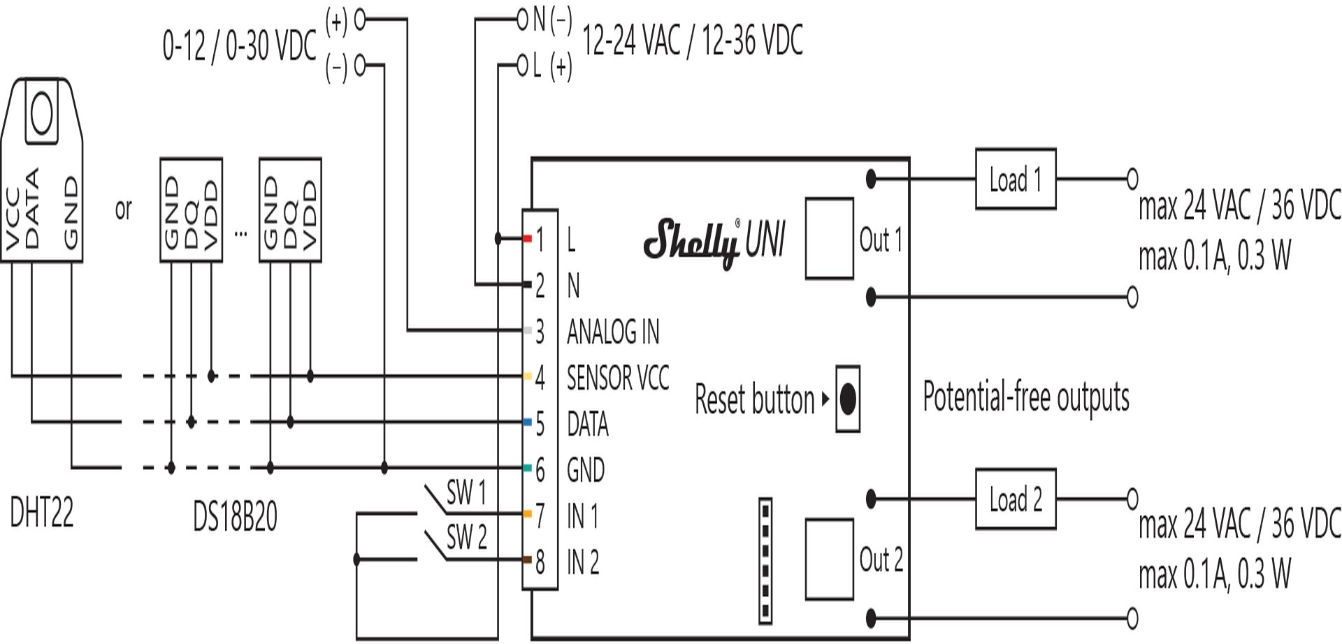
, 0.3W Reset button Potential-free outputs Out 2 Load 2 max 24 VAC / 36 VDC max 0.1A, 0.3W DHT22 DS18B20
in „Multivibrator zur Ansteuerung von Solid State Relais“ · Analoge Elektronik und Schaltungstechnik · · Schaltpläne
-
Bild
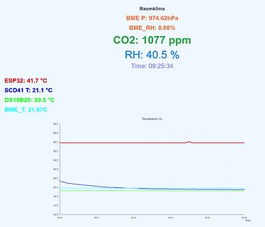
Anzeige von Raumklima-Messwerten und Temperaturverlauf
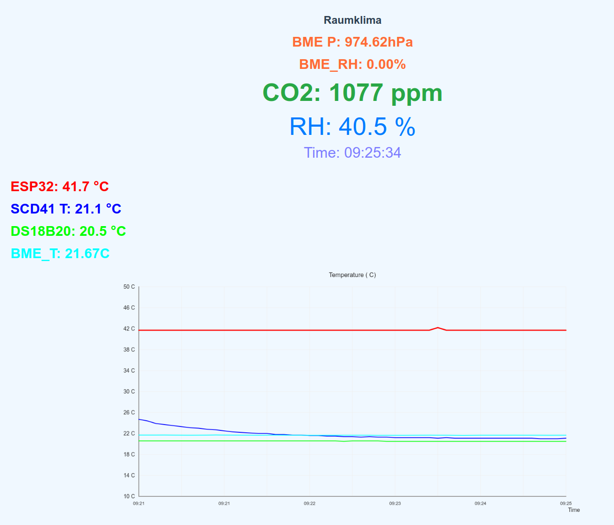
974.62hPa BME_RH: 0.00% CO2: 1077 ppm RH: 40.5 % Time: 09:25:34 ESP32: 41.7 °C SCD41 T: 21.1 °C DS18B20: 20.5 °C BME_T: 21.67C Temperature ( C) 50 C 46 C 42 C 38 C 34 C 30 C 26 C 22 C 18 C 14 C 10 C 09:21 09:21 09:22 09:23 09:24 09:25 Time
in „Micropython Wetterstation“ · Projekte & Code · · Screenshots
-
Bild
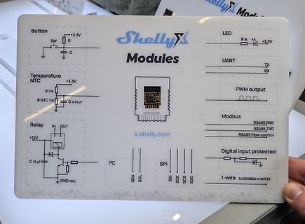
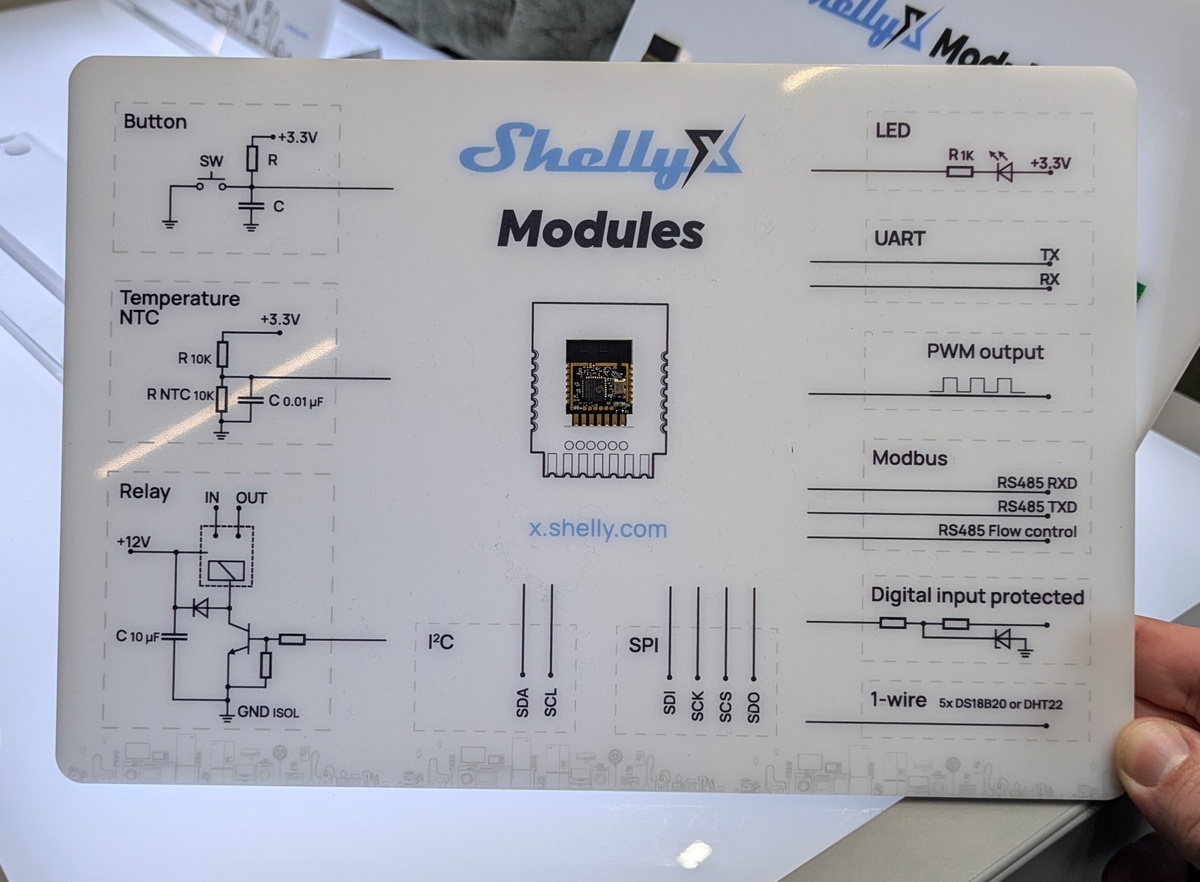
Übersicht der Shelly Modul-Anschlüsse und Schaltpläne
control Relay IN OUT +12V C 10 µF I2C SDA SCL Digital input protected SPI SDI SCK SCS SDO 1-wire 5x DS18B20 or DHT22 x.shelly.com GND ISOL
in „EmbeddedWorld 2026, Catch-All – Bauteile, Stromversorgungen, Meshnetze uvam“ · Mikrocontroller und Digitale Elektronik · · Fotos
-
Datei
init_system.h
Prototypen void Init_Ports(); void Init_BackupRam(); void Init_RTC(); void Init_LCD(); uint8_t Init_DS18B20(); void Init_WorkStructure(Work_t*, size_t); #endif /* INIT_SYSTEM_H_INCLUDED */
in „Organisation der Header und Includes“ · Mikrocontroller und Digitale Elektronik ·
-
Bild
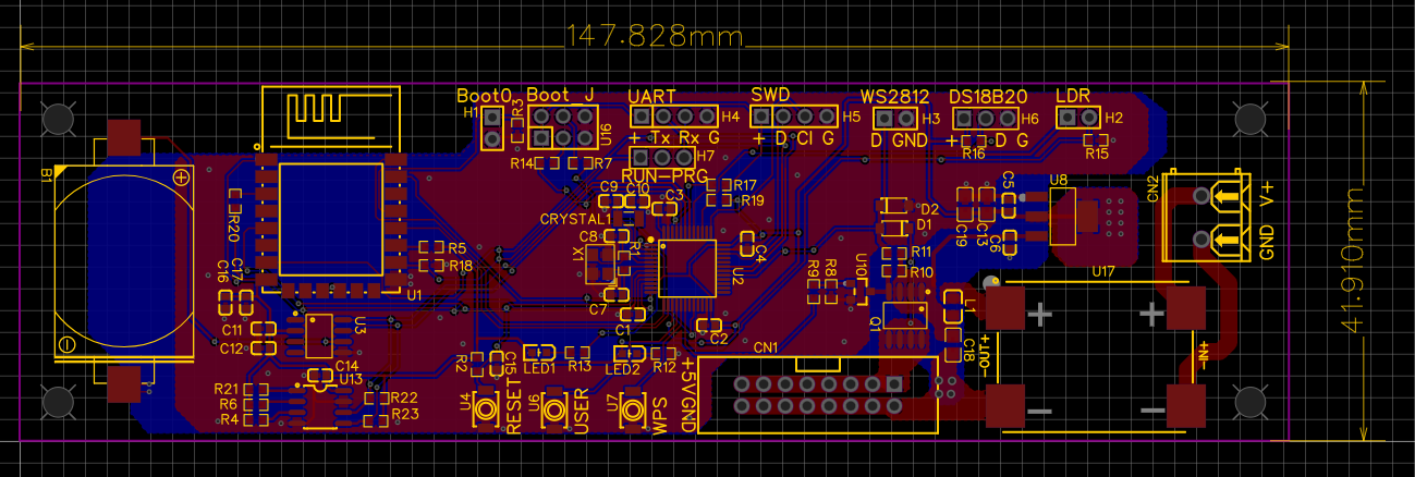
PCB-Layout einer Mikrocontroller-Platine
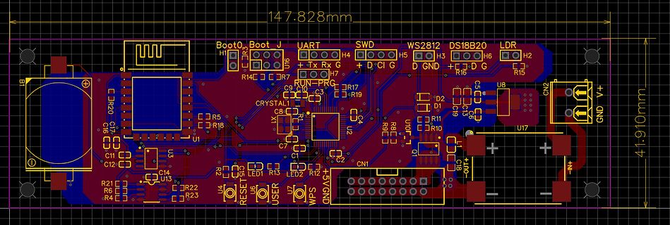
147.828mm 41.910mm Boot0 Boot J UART H4 H5 H3 H6 H2 SWD D C I G D GND D G LDR WS2812 DS18B20 R14 R7 R15 R20 C7 C16 R5 R18 U1 CRYSTAL C8 C9 C3 R17 R19 C11 C12 C14 U3 R21 R6 R4 R22 R23 U13 LED1 R13 LED2 R2 R12 C1 C2 C18 U4 RESET U6 USER U7 WPS 5V GND CN1 CN2 U2 U17 GND V+
in „WordClock mit WS2812“ · Projekte & Code · · Layouts
-
Bild
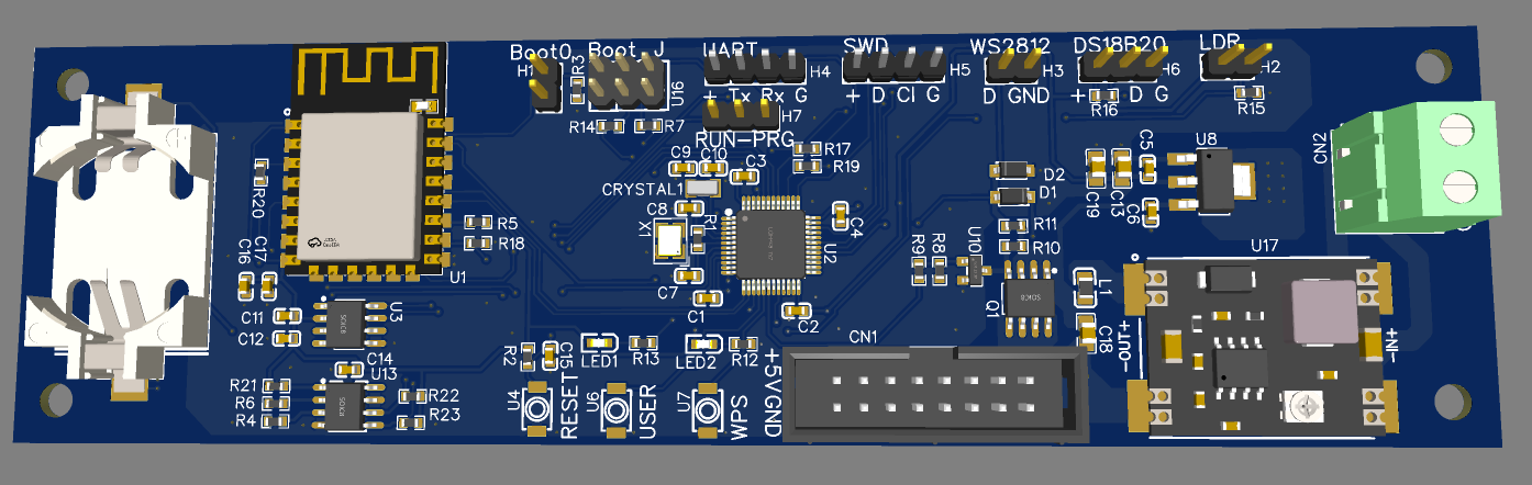
CAD-Ansicht eines Leiterplatten-Layouts
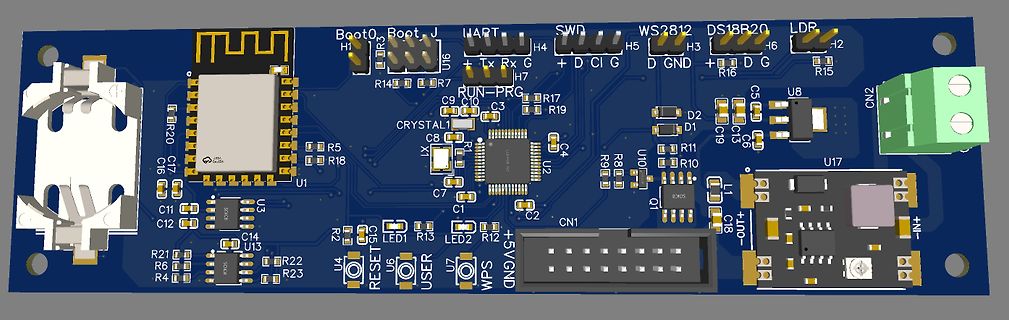
Boot0, Boot J, HART, SWD, WS2812, DS18B20, LDP, H1, H4, H5, H3, H2, U16, R14, R7, R17, R19, R15, R16, D, C, I, G, GND, U8, C5, C15, C19, D2, D1, C16, R20, C7, C9, C10, C3, C8, LX, U2, C4, U1, R5, R18, R8, R9, U10, R11, R10, C6, C1, C2, CN1
in „WordClock mit WS2812“ · Projekte & Code · · Layouts
-
PDF
_LISTE_FAMILY_CODE_V1.pdf
Family Bezeichnung CODE Bemerkung DS1820 x10 Temperatur (nicht mehr produziert) DS18B20 x28 TEMPERATUR DS18S20 x10 Temperatur DS1822 x22 Temperatur DS1920 x10 TEMPERATUR DS1985 x0B ADD ONLY DS2405 x05 Adressable_SWITCH DS2406 x12 Dual Addressable Switch Plus 1kbit Memory DS2407 x12 Dual
in „DS1820 DS18s20 Digital Thermometer 1-wire Beispiele ATmega8 Assembler“ · Projekte & Code ·
-
Datei
Programm_Projekt.c
<avr/io.h> #include <stdlib.h> #include <util/delay.h> #include "lcd-routines.h" #include "therm_ds18b20.h" int main(void) { lcd_init(); char temp [12] = "Temperatur"; uint8_t i = 1, sign = 0; int8_t vor; uint16_t nach; while(1) { // Lese Themperatur als Zahl (Vor- und Nachkommastelle getrennt) i = therm_read_temperature
in „DS18B20: Problem mit Temperaturauslesen“ · Mikrocontroller und Digitale Elektronik ·
-
PDF
Challenge_Langzeitmonitoring_Bodentemperatur.pdf
die Idee verraten. (Ein Referenzsensor würde da mE durchaus Sinn machen). Habe gehört von PT1000 DS18B20 NTC u.a. … Auch die Verkabelung kann ich nur einmal legen. Die Längen derAnbindungsleitungen sind irgendwo zwischen 2 und 20 Metern. Fühlerkabel (mit Löten und Schrumpfschlauch) verlängern kann ich
-
PDF
EL50-150.pdf
IN 1 A 47N60F A Mini-360 R3 R4 R6 R14 4.7k 1K 4.7k R7 100 1k R1 GND RES 20MM GND GND RES 20MM U3 DS18B20 GND GND 3 VDD R5 2 DQ 1K R8 1 GND P4 1k Poti 1 2 3 LM358P B B 1 1OUT VCC 8 R9 2 1IN- 2OUT 7 180K 3 1IN+ 2IN- 6 R15 4 GND 2IN+ 5 180K 8.2K GND R10 P1-GND 102 C1 C2 1 1 GND 102 LED1 1 1 R1k 1k P2 GND
in „Selbsthaltungmit einem Arduino nano“ · Mikrocontroller und Digitale Elektronik ·
-
PDF
HAP-CU-TechDok-20080319.pdf
Eingängen.....................................53 Abb. 4.4: Werteformat beim digitalen Thermometer (DS18B20)...............................55 Abb. 4.5: Werteformat beim digitalen Thermometer (DS18S20)...............................56 Abb. 4.6: Steuerelement Menü..........................................
-
Bild
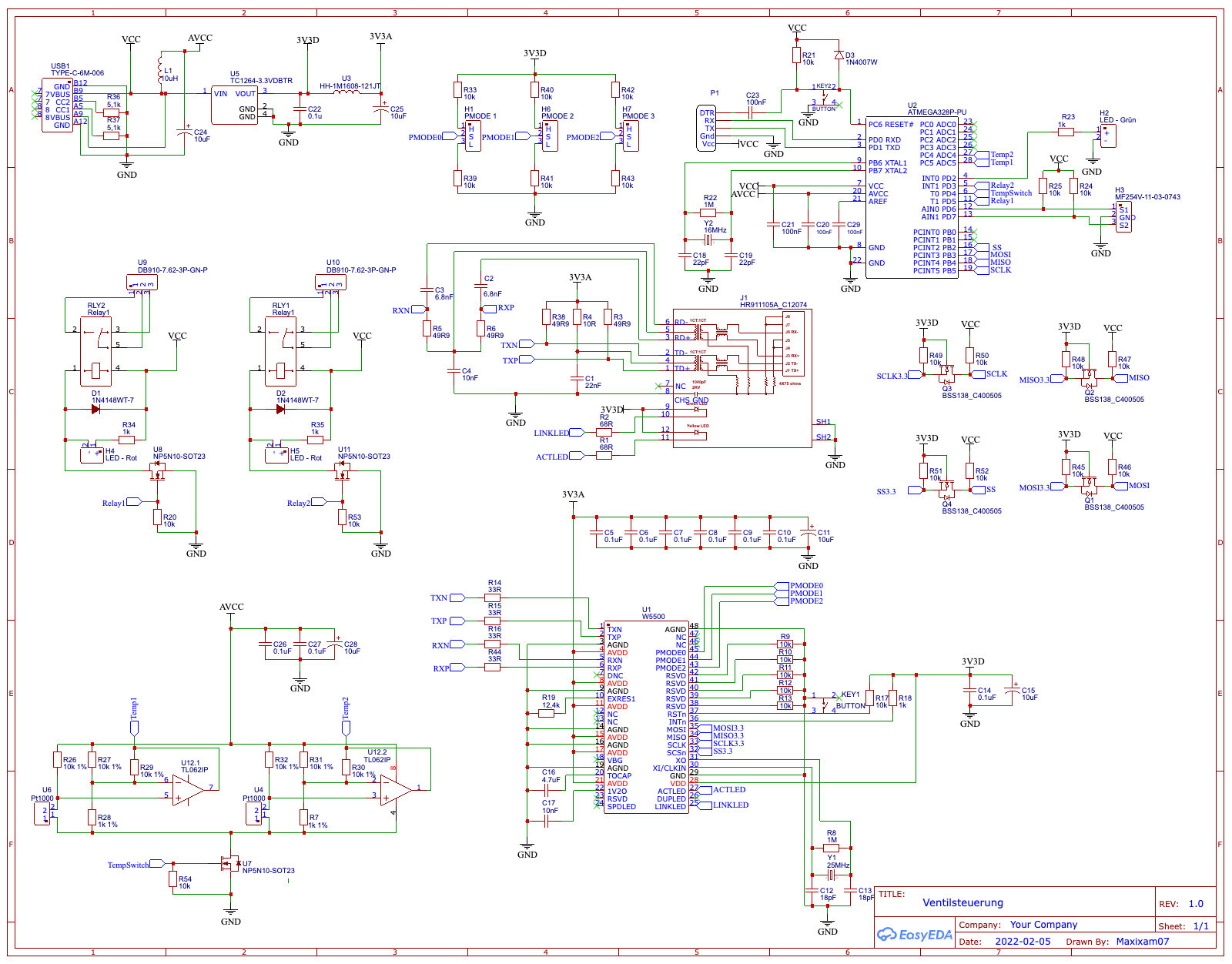
Schaltplan einer Mikrocontroller-Schaltung
C13, 100nF, C12, 100nF, C11, 100nF, C10, 100nF, C9, 100nF, C8, 100nF, C7, 100nF, C6, 100nF, U3, DS18B20-6E2-3P-GN-P, R34, 10k, R35, 10k, R36, 10k, U4, N4148WT-7, U5, N4148WT-7, R37, 10k, R38, 10k, R39, 10k, R40, 10k, R41, 10k, R42, 10k, R43, 10k, R44, 10k, R45, 10k, R46, 10k, R47, 10k, R48, 10k, R49
in „Funktioniert diese Atmega328 Schaltung?“ · Mikrocontroller und Digitale Elektronik · · Schaltpläne
-
Bild
Foto eines Computerbildschirms mit einem Schaltplan
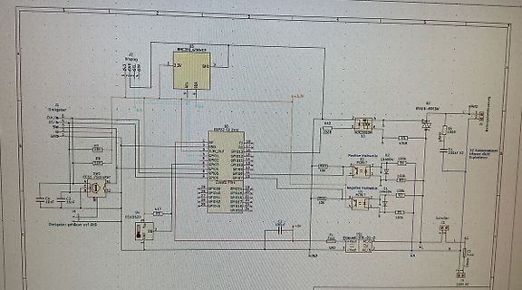
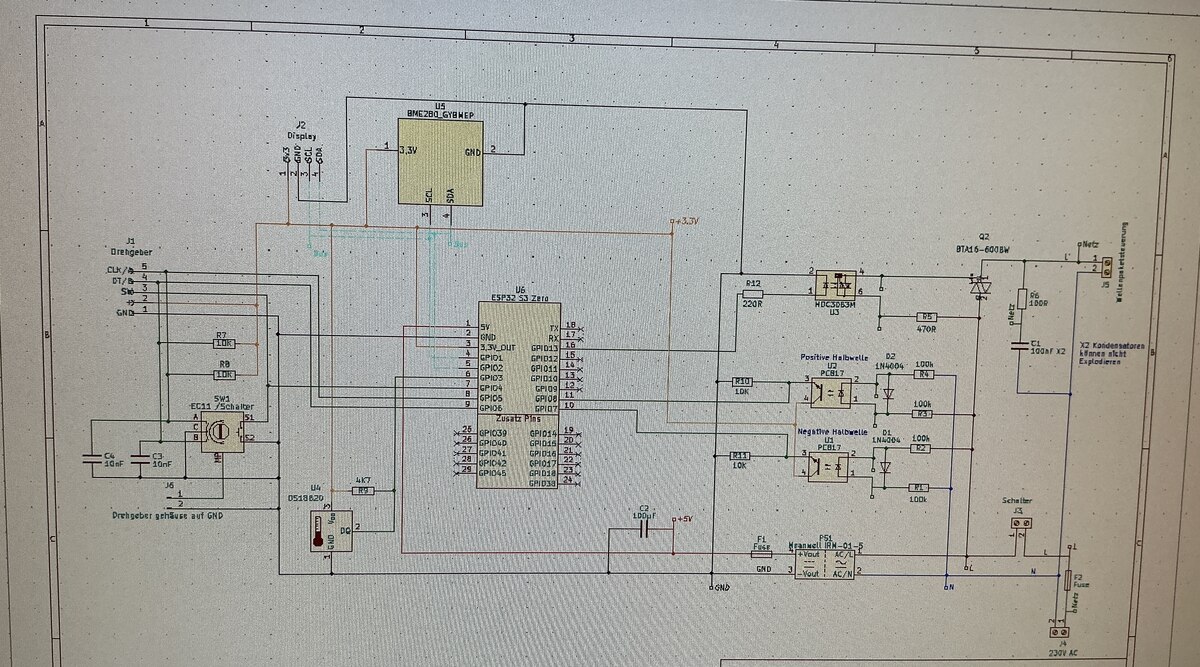
GND SCL SDA U5 BME280_GYBWEP R7 10R R8 10R SW1 Schalter U6 ESP32-S3 Zeil C4 10uF C3 1gf R9 47R U4 DS18B20 DG 2 R10 220R R12 220R Q2 BTA16-600B U2 Positive Halbwelle IN4004 100k R11 1k R13 100k U3 Negative Halbwelle IN4004 100k R15 10k R14 470R C1 100nF C2 100nF R1 100k R2 100k R3 100k R4 100k R5 100k
in „ESP32 S3 Zero WLAN Probleme“ · Mikrocontroller und Digitale Elektronik · · Fotos
-
Datei
Aenderungen.txt
----------------------------------------- String FARBE; String col_defective = ""; /* Fkt um bei DS18B20 Fehler Farbe der Fehlermeldung zu aendern */ String readDSTemperatureERR_col() { if((!err_tempC)&&(!err_tempF)&&(!zu_kaltC)&&(!zu_kaltF)) { FARBE = "color: blue"; } else { FARBE = "color: red"; }
in „HTML Anzeige - Farbe Meldetext ändern“ · Mikrocontroller und Digitale Elektronik ·
-
Datei
outval.txt
* */ ;* Author: Peter Dannegger */ ;* danni@specs.de */ ;* mit Aenderungen f. Temperatursensor ( DS18B20 ) von Unbekannt */ ;************************************************************************/ ;************************************************************************/ ;--------------------------
-
Bild
Schaltplan eines Mikrocontroller-basierten Systems mit zwei PCBs
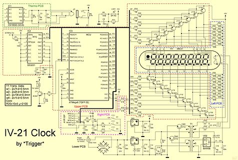
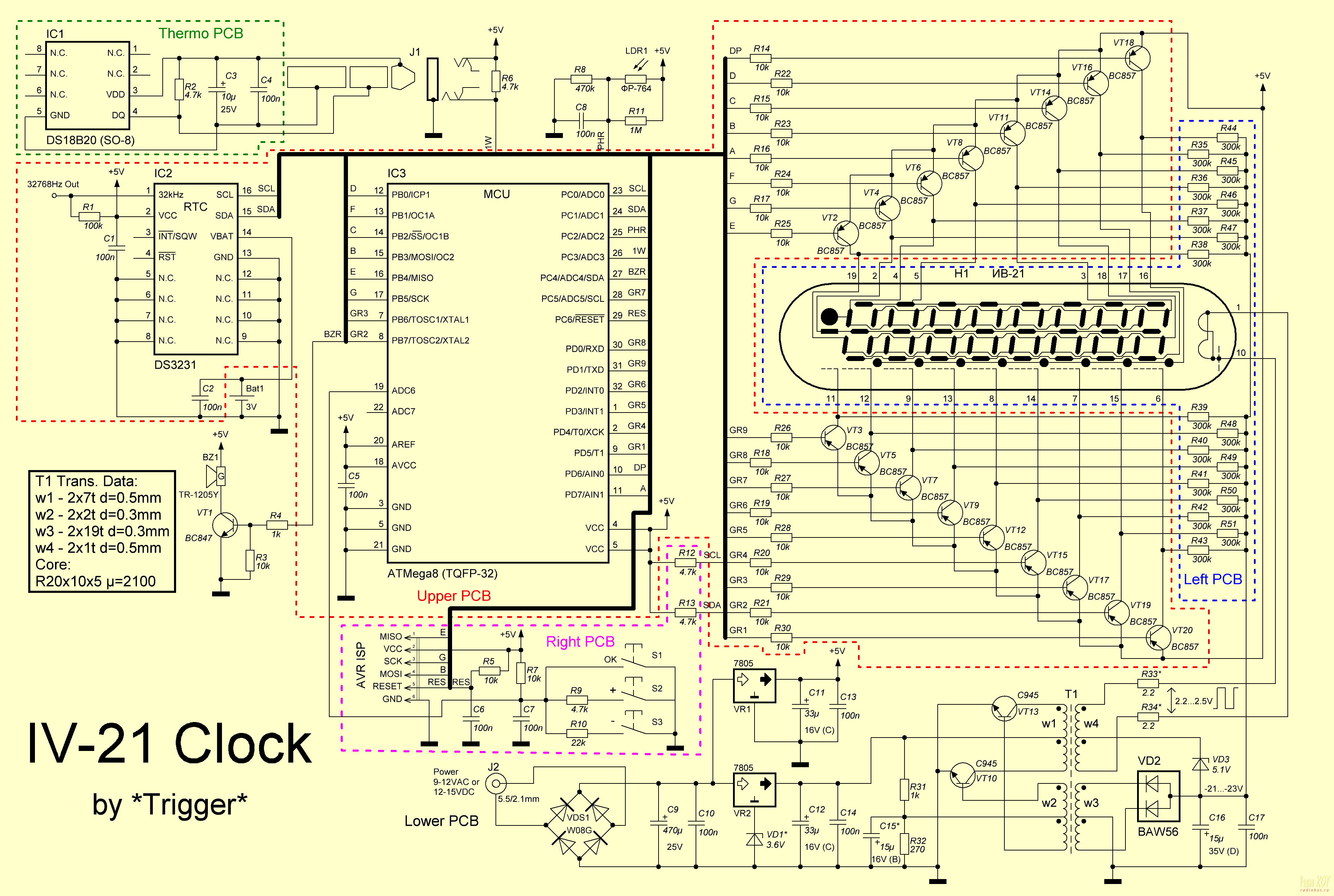
Thermo PCB IC1 DS18B20 (SO-8) IC2 ATmega (TQFP-32) IC3 MCU R2 376ohm C1 100n C3 C4 C5 C7 C8 C11 R3 4.7k R8 470k LDR1 R10 1M R15 10k R16 10k R17 10k R22 BC857 R23 BC857 R24 BC857 R25 BC857 R26 BC857 R27 BC857 R28 BC857 R29
in „TPS61010 - Reset durch Lastprung verhindern“ · Analoge Elektronik und Schaltungstechnik · · Schaltpläne
-
Datei
ds1820.h
0xBE #define DS1820_CMD_COPYSCRPAD 0x48 #define DS1820_CMD_RECALLEE 0xB8 #define DS1820_FAMILY_CODE_DS18B20 0x28 #define DS1820_FAMILY_CODE_DS18S20 0x10 /* ---------------------------------------------------------------------------- */ /* LED1 and LED2 Definitions */ /* ---------------------------------
in „ds18b20 temperaturmessung mit pic18f4550“ · Mikrocontroller und Digitale Elektronik ·
-
Datei
beispiel.ino
dataString = String(id) + "," + String(sensors.getTempCByIndex(0)); // You can have more than one DS18B20 on the same bus (0 refers to the first IC on the wire). // open the file. note that only one file can be open at a time, // so you have to close this one before opening another. File dataFile = SD.open
in „Arduino auf SD-Karte kann nicht geschrieben werden“ · Mikrocontroller und Digitale Elektronik ·
-
Datei
TempCalc.asm
**************************************************** * Berechnung und Ausgabe der Rohwerte eines DS18B20 * * Rohwerte in RawLow und Rawhigh übergeben worden * * Direkte Anzeige und Ausgabe auf UART und/oder * * Speichern des Temperaturwertes in Tempcopy * * incl. Vorzeichen, Komma und °C (+xx,xx°C) *
-
PDF
app162__Interfacing_DS1820_in_a_MC_environment_.pdf
for interfacing 1- Detailed timing and operational information for the TM Wire devices such as the DS18B20, DS18S20 or DS18B20, DS18S20 and DS1822 is available in their DS1822 to a microcontroller. These methods range respective datasheets, which can be obtained from from simple software solutions, to
in „DS18B20 zu komplizierte Ansteuerung?“ · Mikrocontroller und Digitale Elektronik ·
-
PDF
app162__Interfacing_DS1820_in_a_MC_environment_.pdf
for interfacing 1- Detailed timing and operational information for the TM Wire devices such as the DS18B20, DS18S20 or DS18B20, DS18S20 and DS1822 is available in their DS1822 to a microcontroller. These methods range respective datasheets, which can be obtained from from simple software solutions, to
-
Datei
thermometer_test.htm
font-size: 1.5rem; vertical-align:middle;padding-bottom: 15px;color:red;} </style> </head> <body> <h2>DS18B20 HaWi</h2> <h4>Version V1.0, 03.11.2024</h4> <p> <i class="fas fa-thermometer-half" style="color:#059e8a;"></i> <span class="ds-labels">Temperatur:</span> <span id="temperaturec">%TEMPERATUREC%</span
in „HTML Anzeige - Farbe Meldetext ändern“ · Mikrocontroller und Digitale Elektronik ·
-
Datei
testtemp.c
Jens */ #include <stdint.h> #include <stdio.h> /** * Scratchpad scmsb, sclsb, remain * * family ds18B20 = 0x28 * ds18S20 = 0x10 */ int16_t gettemp(uint8_t scmsb, uint8_t sclsb, uint8_t remain, uint8_t family) { int16_t temp = 0; int16_t rem; float rtemp; if (family == 0x10) { temp = (int16_t) (scmsb
in „DS18S20 und DS18B20 gemeinsam am Bus - Temperaturkonvertierung“ · Mikrocontroller und Digitale Elektronik ·
-
Datei
Assembly1.s
equ TAKT =16000000 .equ LCD_PORT = PORTB .equ LCD_DDR = DDRB .equ PIN_RS = 4 .equ PIN_E = 5 .equ DS18b20 = 7 .equ DS_PORT =PORTd .equ DS_PIN = PINd .equ DS_DDR =DDRd .equ out_ddr =DDRC init: ldi temp1, HIGH(RAMEND) out SPH, temp ldi temp1, LOW(RAMEND) ; Stackpointer initialisieren out SPL, temp ldi temp
in „ds18s20 atmega16 asm“ · Mikrocontroller und Digitale Elektronik ·
-
Datei
onewire.c
/* ds18b20 lib 0x02 copyright (c) Davide Gironi, 2012 Released under GPLv3. Please refer to LICENSE file for licensing information. */ #include <avr/interrupt.h> #include <stdio.h> #include <stdlib.h> #include
in „Delay mit Timer“ · Mikrocontroller und Digitale Elektronik ·
-
Datei
sketch_jan22a1.ino
tempC == -127.00) { // device disconnected code for Celsius Serial.print("Error getting temperature, DS18B20 disconnected"); } return (tempC); // Gibt den Wert in °C zurueck } // ende gibTemp() // =================================================================== // // ==================================
in „Arduino DS18S20 geziehlt auslesen!“ · Mikrocontroller und Digitale Elektronik ·
-
Datei
sketch_jan22a11.ino
tempC == -127.00) { // device disconnected code for Celsius Serial.print("Error getting temperature, DS18B20 disconnected"); } return (tempC); // Gibt den Wert in °C zurueck } // ende gibTemp() // =================================================================== // // ==================================
in „Arduino DS18S20 geziehlt auslesen!“ · Mikrocontroller und Digitale Elektronik ·
-
Datei
Temp_LCD.c
| (1<<MUX0); //int. REF= 2.56 V activate | ADC1 messure //lcd_puts(" ADC TEST U= 2V"); lcd_puts("DS18B20 TEST"); for (t=25;t;t--) { _delay_ms(30); } lcd_init (LCD_DISP_ON); lcd_clrscr (); int temperature = 0; char buffer [3]; for (;;) { read_scratchpad (); temperature = (scratchpad [1] << 8) + scratchpad
in „DS18B20 + LCD + ATmega will nicht funktionieren“ · Mikrocontroller und Digitale Elektronik ·
-
Datei
main.c
Drucksensor CalcSonnenAufgang(&Time,&SonnenZeiten); // Sonnenaufgang und Untergang berechnen // Init_DS18B20(); Init_LCD(); // LCD einstellen // Daten ungültig machen, wenn Userbutton beim Reset gedrückt wurde if (TM_DISCO_ButtonPressed()) { Work.id = 0; Init_WorkStructure(&Work, sizeof(Work)); } // LCD
in „Organisation der Header und Includes“ · Mikrocontroller und Digitale Elektronik ·
-
Datei
familycode10.txt
clock DS2415 24 Real time clock DS2438 26 Temperature, A/D DS2417 27 Real time clock with interrupt DS18B20 28 Adjustable resolution temperature DS2408 29 8-channel addressable switch DS2890 2C single channel digital potentiometer DS1972 2D 1024-bit, 1-Wire EEPROM DS2431 2D 1024-bit, 1-Wire EEPROM DS2760
in „DS1820 DS18s20 Digital Thermometer 1-wire Beispiele ATmega8 Assembler“ · Projekte & Code ·
-
PDF
Projekt_Heimautomation.pdf
Temperatursonden - OpenSource: IchlegealleBaupläneundQuellcodes offen. Wer will, kann es nachbauen. (DS18B20), die bereits einen vorimplemen- tierten1-wire-Busenthalten.DerBausteinsoll - StandardisiereSchnittstellen:EssollennurSchnitt- die Temperaturen messen und per CAN an die stellen zum Einsatz kommen
in „Schaltplan für Haussteuerung im Hutschienengehäuse (Raspberry Pi, CAN, MCP2515, MCP2562, PCF8574)“ · Haus & Smart Home ·
-
Datei
main.c
as 2 bytes } else { minus=1; d = (a & 0x000f); c = a>>4; } centigrade = minus*(c+(d/16.0)); //The DS18B20 is pre-calibrated // The following block prints "Temp" and degrees centigrade on the first line for (j=0; j<8; j++){array[j] = 0x00;} //Fill array with 00h sprintf(array,"%5.4f",centigrade); //Format
in „DS18B20 Tempsensor mit PIC18F - Oszillatorprobleme?“ · Mikrocontroller und Digitale Elektronik ·
-
Datei
Nano.txt
Serial.print(temp5); Serial.print(" C"); return tr - (float)0.25 + (cpc - cr)/(float)cpc; } else // DS18B20 { return ((data[1] << 8) + tr) * (float)0.0625; } return; }
in „C# Temp werte als label anzeigen“ · Softwareentwicklung ·
-
PDF
CodeBoard_2_0_Schematic.pdf
P33-INT1 P37-RD O P O P O P O P JP7 JP6 JP5 JP4 JP3 GND 17 P34-T0 18 7 8 5 6 3 4 1 2 1-wire für 5x DS18B20 (digi. Temperatursensor) P35-T1 P36-WR 8051N-SOCK 4 3 2 1 A 2 4 6 +5V +5V +5V +5V GND +5V A D C-UPLINK A 1 3 5 5 k 4 k M +5V +5V +5V R 1 R 1 IC3 4 5 13 2 5 T 5 T CLK DIG0 11 B B 12 DIG1 6 2 0 3 0
in „8051: An Port 0 kann nichts ausgegeben werden“ · Mikrocontroller und Digitale Elektronik ·
-
PDF
CodeBoard_2_0_Schematic.pdf
P33-INT1 P37-RD O P O P O P O P JP7 JP6 JP5 JP4 JP3 GND 17 P34-T0 18 7 8 5 6 3 4 1 2 1-wire für 5x DS18B20 (digi. Temperatursensor) P35-T1 P36-WR 8051N-SOCK 4 3 2 1 A 2 4 6 +5V +5V +5V +5V GND +5V A D C-UPLINK A 1 3 5 5 k 4 k M +5V +5V +5V R 1 R 1 IC3 4 5 13 2 5 T 5 T CLK DIG0 11 B B 12 DIG1 6 2 0 3 0
in „8051: An Port 1 nur 3.5V anstatt 5V ?“ · Mikrocontroller und Digitale Elektronik ·
-
Datei
ds1820.c
: Where the device are on the port Output: Temp in C * 10 or 9999 if no device present Misc: for DS18B20 NOT DS1820 **********************************************************/ int GetTemp(unsigned char mask) { unsigned char msb,lsb; unsigned char negative; int i; if (!OneWireReset(mask)) return 9999;
in „AVR-GCC DS1820 C-Code“ · Mikrocontroller und Digitale Elektronik ·
-
Datei
oliver_ds1820.c
den bus wieder auf low zieht r = (bit_is_clear(T_PIN, T_DQ) ? 1 : 0); // bit clear also muss der DS18B20 den pin auf low gezogen haben T_OUTPUT; // als ausgang setzen _delay_us(410); #endif return r; } inline void owWriteBit(uint8_t bit_value) { cli(); T_OUTPUT; if (bit_value) // Write 1 { T_LOW; //

in „1Wire Problem - mal wieder - mit DS18B20 in C“ · Mikrocontroller und Digitale Elektronik ·