-
Datei
msp430g2xx1_ta_uart9600.c
//****************************************************************************** // MSP430G2xx1 Demo - Timer_A, Ultra-Low Pwr UART 9600 Echo, 32kHz ACLK // // Description: Use Timer_A CCR0 hardware output modes and SCCI data latch // to implement UART function @ 9600 baud. Software does
in „MSP430 launchpad TimerA_UART“ · Mikrocontroller und Digitale Elektronik ·
-
Datei
A--0191c-i-DS10_be-kon_Ka09_b.c
29.8.21 //Änderungen: /************************************************************************/ // MSP430F1611 // ----------------- // | XIN|- 32,768kHz // | | | // Taster rot--|RST (58) XOUT|- 32,768kHz //8 MHz X2OUT- | P1.0..P1.7|Daten FKA LMK62 // 8 Mhz X2IN- | | // | P3.0| frei (28) Stecker umbauen
in „Sende/Empfangsvorgang mittels nur 1St. µC“ · Mikrocontroller und Digitale Elektronik ·
-
 Bild
Bild
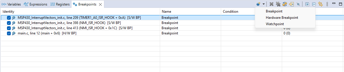
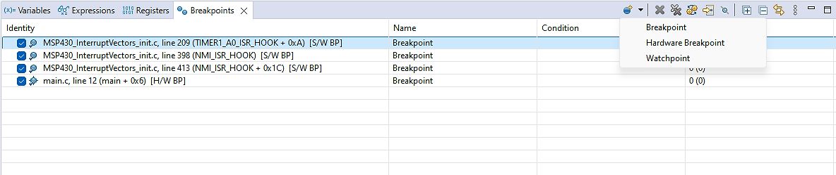
Breakpoint-Liste in einer Debugging-Software
Variables Expressions Registers Breakpoints Identity MSP430_InterruptVectors_init.c, line 209 (TIMER1_A0_ISR_HOOK + 0xA) [S/W BP] Name Condition Breakpoint Breakpoint Hardware Breakpoint NMI_ISR_HOOK [S/W BP] Watchpoint MSP430_InterruptVectors_init.c, line
in „MSP430 startet sporadisch neu“ · Mikrocontroller und Digitale Elektronik · · Screenshots
-
PDF
Visio-Struktur_uc.pdf
Jahr S3 GPS über USB Schnittstelle für Wandler externen Speicher Taktsignal vom Messung 1 Sensor MSP430 S4 GPS Messung 2 Mittelwert errechnen Taktsignal Messung 1 Sensor Messung 2 S5 GPS Berechnung der Absolut- Schneckenge GPS-Empfänger zur Sonnenlaufbahn Drehgeber triebe DC/ Synchronisation der Motor
in „Welcher MSP430?“ · Mikrocontroller und Digitale Elektronik ·
-
Datei
Main.c
//****************************************************************************** // MSP430F2132 // // // // Name: Andreas Mohr // Projekt: LCD Test // Version: 1.2 // Erstellt: 15.05.11 //****************************************************************************** #include "msp430x21x2
in „8 bit LCD an MSP430F2132“ · Mikrocontroller und Digitale Elektronik ·
-
Datei
SM_4_Kanal_0_5s_ADC12.c
/* **SMART MEDIA Karte beschreiben MSP430-ADC12 **/ /*********************************************************************/ /**Programm wartet auf Start durch P1.5 */ /* Karte vorher unbedingt ECHT löschen FF mit WINHEX geht nicht!!! */ /*
in „MSP430F149: digitalisierte Daten in das Flash M. speichern“ · Mikrocontroller und Digitale Elektronik ·
-
Datei
code.c
#include <msp430x16x.h> #include <msp430def.h> #pragma interrupt_handler timera_isr: TIMERA0_VECTOR timera_isr: TIMERA1_VECTOR #pragma interrupt_handler timerb_isr: TIMERB0_VECTOR timerb_isr: TIMERB1_VECTOR #pragma
in „[MSP430] Variablenuebergabe an ISR“ · Mikrocontroller und Digitale Elektronik ·
-
Datei
code_funzt.c
#include <msp430x16x.h> #include <msp430def.h> #pragma interrupt_handler timera_isr: TIMERA0_VECTOR timera_isr: TIMERA1_VECTOR #pragma interrupt_handler timerb_isr: TIMERB0_VECTOR timerb_isr: TIMERB1_VECTOR #pragma
in „[MSP430] Variablenuebergabe an ISR“ · Mikrocontroller und Digitale Elektronik ·
-
Datei
control1.c
#include <msp430x16x.h> #include <msp430def.h> void timera_init(); void timerb_init(); void mittel(); void init_DAC(); void init_SIO(); void init_ADC(); void wait_05ms(); #pragma interrupt_handler timera_isr: TIMERA0
in „MSP430 Timing Probleme“ · Mikrocontroller und Digitale Elektronik ·
-
Datei
main.c
//****************************************************************************** // MSP430G2xx3 Demo - USCI_A0, SPI 3-Wire Master Incremented Data // // Description: SPI master talks to SPI slave using 3-wire mode. Incrementing // data is sent by the master starting at 0x01. Received data
in „MSP430 G2553 mit DOGL128W-6 Display“ · Mikrocontroller und Digitale Elektronik ·
-
Datei
main.c
// lcd Pollin C0802 an TI Launchpad mit msp430g2452 CPU (an Port2) // MSP430G2452: 16IO 8K 256RAM 16BitTimer Watchdog BOR I2C/SPI Comp TempS 8ChADC10 // delay functions for lcd calculated for internal DCO with default 1MHz // internal Temp mesured
in „MSP430 Launchpad lcd Ansteuerung, Vergleic. Atmel AVR“ · Projekte & Code ·
-
Datei
uart.c
#include <msp430x12x.h> #define MCU_CYCLE 800000 #include <msp430x11x1.h> #define WAIT_ms(x) wait((MCU_CYCLE*(x)/1000)/4); #define UP 0x01 extern wait (); void main(void) { WDTCTL = WDTPW + WDTHOLD; // watchdog - Timer
in „UART-Echo am MSP430F1232“ · Mikrocontroller und Digitale Elektronik ·
-
Datei
bauteile_001.txt
PIC16C56A/JW DIL Microchip 2 2,00 6 PIC18F242-I/SP DIL Microchip 3 3,00 3 LPC2101F TQFP 3 3,00 9 MSP430F1121A TSSOP TI 9 4,00 5 MSP430F149I LQFP TI 5 9,00 60 29F040C-70 PLCC 60 6,00 1 10 25P10AVG ST 10 3,00 ------------------------------------------------------------------------------------- Alles komplett
in „Verkaufe diverse Bauteile“ · Markt ·
-
Datei
Blinktimer_C.c
Timer-interrupt soll LED alle 2s aufleuchten lassen, ; später soll dort ein anderes Programm stehen ; ; MSP430F133 ; _________________ ; /|\| XIN|- ; | | | ; --|RST XOUT|- ; | | ; | P1.0|-->LED (12) ; ; Dale Wellborn ; Texas Instruments, Inc ; June 2001 und Wolfgang Dez.2003 ;****************************************************************************** */ #include <msp430x13x.h> void main(void) { WDTCTL = WDTPW + WDTHOLD; // Stop watchdog timer P1DIR = BIT0; // P1.0 output TACTL = TASSEL0+TACLR ; //TASSEL1=SMCLK,TASSEL0=ACLK(32,7..kHz), clear TAR CCTL0 = CCIE ; //CCR0
in „MSP 430 Wie Timer in C programmieren?“ · Mikrocontroller und Digitale Elektronik ·
-
Datei
TimerWo_133.c
Toggle P1.0 using using software and TA_0 ISR. // die LED wird alle 5ms 5x AUS/EIN-geschaltet // MSP430F133 // --------------- // /|\| XIN|- // | | | // --|RST XOUT|- // | | // | P1.0|-->LED // // M. Buccini + Wolfgang // Texas Instruments, Inc & Ich // January 2002+ Dez. 2003 // Built with IAR Embedded
in „MSP 430 Wie Timer in C programmieren?“ · Mikrocontroller und Digitale Elektronik ·
-
 Bild
Bild
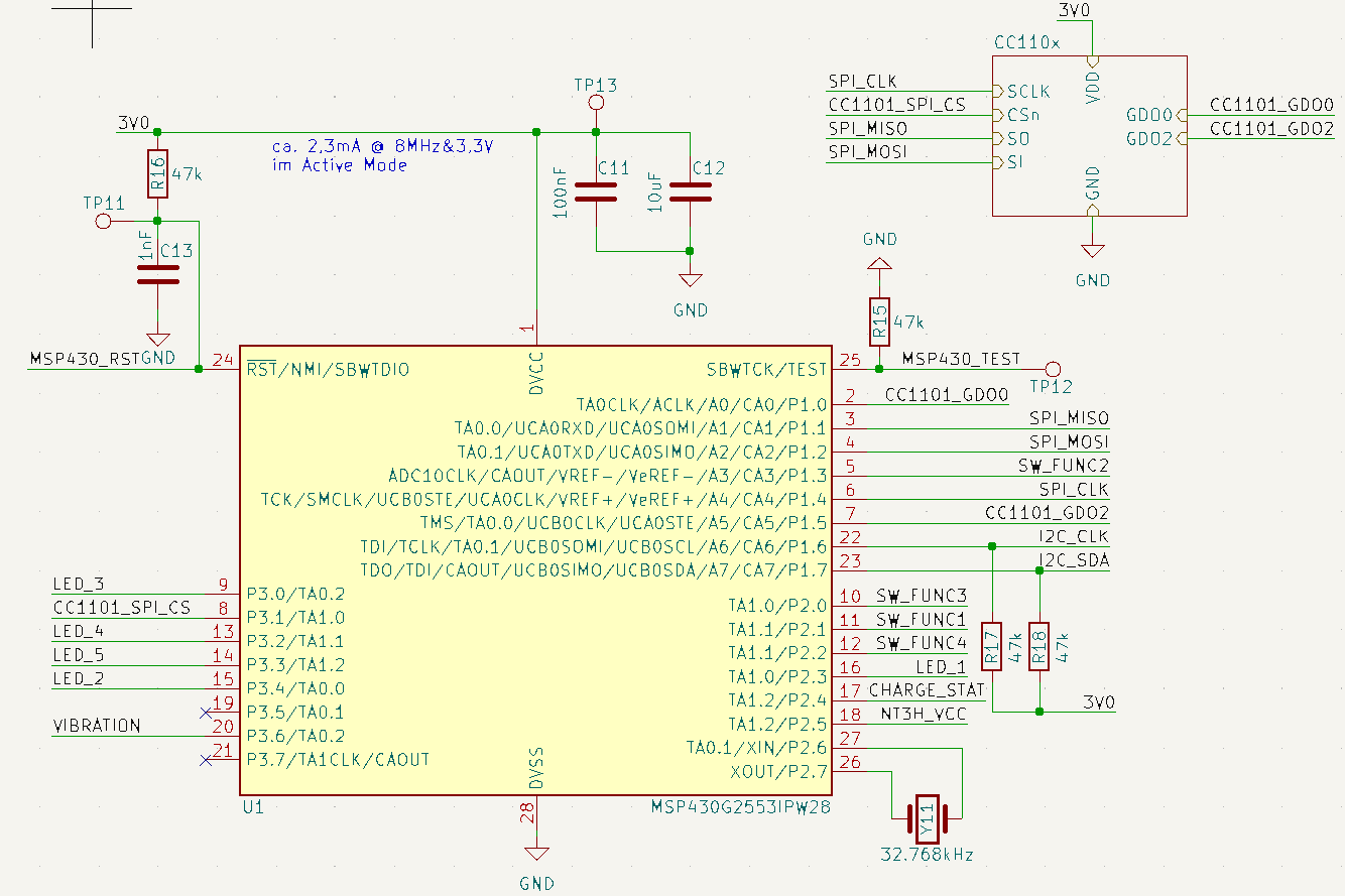
Schaltplan eines MSP430G2553 Mikrocontrollers
DSCLK, SPI_MISO, CSn, SPI_MOSI, DSO, SI, VDD, CC1101_GD00, GD00, CC1101_GD02, GD02, GND, R15, 47k, MSP430_TEST, TP12, 24, RST/NMI/SBWTDIO, 25, MSP430, 2, CC1101_GD00, 3, TA0.0/ACLK/CAO/P1.0, SBWTCK/TEST, 4, TA0.1/UCAORXD/UCAOSDMI/A1/CA1/P1.1, TA0.1/UCAOXTD/UCAOSI/A2/CA2/P1.2, ADC10CLK/CAOUT/VREF-/VEREF
in „CC1101: Unsauberes Signal beim Senden“ · HF, Funk und Felder · · Schaltpläne
-
Datei
bauteile_003.txt
PIC16C56A/JW DIL Microchip 2 2,00 6 PIC18F242-I/SP DIL Microchip 3 3,00 3 LPC2101F TQFP 3 3,00 9 MSP430F1121A TSSOP TI 9 4,00 5 MSP430F149I LQFP TI 5 9,00 60 29F040C-70 PLCC 60 6,00 1 10 25P10AVG ST 10 3,00 1) Hierbei handelt es sich um Schüttgut, möglicherweise schon programmiert.
in „Verkaufe diverse Bauteile“ · Markt ·
-
Datei
fet140_ta_05.c
default DCO ~800kHz // //* An external watch crystal on XIN XOUT is required for ACLK *// // // MSP430F149 // --------------- // /|\| XIN|- // | | | 32kHz // --|RST XOUT|- // | | // | P1.0|-->LED // // M. Buccini // Texas Instruments Inc. // Feb 2005 // Built with IAR Embedded Workbench Version: 3.21A //****************************************************************************** #include <msp430x14x.h> void main(void) { WDTCTL = WDTPW + WDTHOLD; // Stop WDT P1DIR |= 0x01; // P1.0 output CCTL0 = CCIE; // CCR0 interrupt enabled CCR0 = 1000-1; TACTL = TASSEL_1 + MC_1; // ACLK, upmode _BIS_SR(
in „anfänger frage:Timer_A mit MSP430“ · Mikrocontroller und Digitale Elektronik ·
-
Datei
lsusboutput.txt
0x15ba Olimex Ltd. idProduct 0x0002 bcdDevice 1.00 iManufacturer 1 Silicon Labs iProduct 2 OLIMEX MSP430 JTAG TINY iSerial 3 030006B4 bNumConfigurations 1 Configuration Descriptor: bLength 9 bDescriptorType 2 wTotalLength 32 bNumInterfaces 1 bConfigurationValue 1 iConfiguration 0 bmAttributes 0x80 (Bus
in „MSP430 programmieren/debuggen unter Linux“ · Mikrocontroller und Digitale Elektronik ·
-
Datei
bauteile_002.txt
PIC16C56A/JW DIL Microchip 2 2,00 6 PIC18F242-I/SP DIL Microchip 3 3,00 3 LPC2101F TQFP 3 3,00 9 MSP430F1121A TSSOP TI 9 4,00 5 MSP430F149I LQFP TI 5 9,00 60 29F040C-70 PLCC 60 6,00 1 10 25P10AVG ST 10 3,00 1) Hierbei handelt es sich um Schüttgut, möglicherweise schon programmiert.
in „Verkaufe diverse Bauteile“ · Markt ·
-
Datei
msp_server.h
#ifndef _MSP430SERVER_H_ #define _MSP430SERVER_H_ // #include "typedefs.h" #include "stdint.h" // void configureW5500(const uint8_t *sourceIP, const uint8_t *gatewayIP, const uint8_t *subnetMask); void resetW5500(
in „Send response (Action *Var)“ · Mikrocontroller und Digitale Elektronik ·
-
Datei
fet440_ta01.c
normally off and // used only durring TA_ISR. // ACLK = n/a, MCLK = SMCLK = TACLK = DCO ~ 800kHz // // MSP430F449 // --------------- // /|\| XIN|- // | | | // --|RST XOUT|- // | | // | P5.1|-->LED // // M.Buccini // Texas Instruments, Inc // January 2002 // Built with IAR Embedded Workbench Version: 1.25A //****************************************************************************** #include <msp430x44x.h> void main(void) { WDTCTL = WDTPW + WDTHOLD; // Stop WDT TACTL = TASSEL1 + TACLR; // SMCLK, clear TAR CCTL0 = CCIE; // CCR0 interrupt enabled CCR0 = 10000; P2DIR |= 0x04; // P5.1 output TACTL
in „MSP430 als Taktgeber nutzen“ · Mikrocontroller und Digitale Elektronik ·
-
Datei
fet140_ta01.c
normally off and // used only durring TA_ISR. // ACLK = n/a, MCLK = SMCLK = TACLK = DCO ~ 800k // // // MSP430F149 // --------------- // /|\| XIN|- // | | | // --|RST XOUT|- // | | // | P1.0|-->LED // // M. Buccini // Texas Instruments, Inc // January 2002 // Built with IAR Embedded Workbench Version: 1.25A //****************************************************************************** #include <msp430x14x.h> void main(void) { WDTCTL = WDTPW + WDTHOLD; // Stop WDT TACTL = TASSEL1 + TACLR; // SMCLK, clear TAR CCTL0 = CCIE; // CCR0 interrupt enabled CCR0 = 50000; P1DIR |= 0x01; // P1.0 output TACTL
in „MSP 430 Wie Timer in C programmieren?“ · Mikrocontroller und Digitale Elektronik ·
-
Datei
main.c
the contents of ADC12MEM0. // ACLK = n/a, MCLK = SMCLK = default DCO, ADC12CLK = ADC12OSC // // MSP430F449 // --------------- // | | // Vin -->|P6.0/A0 | // | | // // // M. Mitchell // Texas Instruments Inc. // Feb 2005 // Built with CCE Version: 3.2.0 and IAR Embedded Workbench Version: 3.21A //****************************************************************************** #include <msp430x44x.h> void main(void) { WDTCTL = WDTPW+WDTHOLD; // Stop watchdog timer P6SEL |= 0x01; // Enable A/D channel A0 //ADC12CTL0 = ADC12ON+SHT0_15 + REFON + REF2_5V; ADC12CTL0 = ADC12ON+SHT0_2; // Turn
in „MSP430-449STK2 ADC“ · Mikrocontroller und Digitale Elektronik ·
-
Datei
RTC_Sample_03.c
//****************************************************************************** // // MSP430F5418 // ----------------- // /|\ | XIN|- // | | | 32kHz // ---|RST XOUT|- // | | // | P6.1|-->LED // // Built with IAR Embedded Workbench Version: 4.20 //****************************************************************************** #include <msp430x54x.h> extern int SetRTCYEAR(int year); extern int SetRTCMON(int month); extern int SetRTCDAY(int day); extern int SetRTCHOUR(int hour); extern int SetRTCMIN(int min); extern int SetRTCSEC(int sec)
in „MSP430 RTC Alarm Interrupt“ · Mikrocontroller und Digitale Elektronik ·
-
Datei
fet140_adc12_02.c
results, open an ADC12 // register window in debugger and view the contents of ADC12MEM0. // // // MSP430F149 // --------------- // | | // Vin -->|P6.0/A0 | // | | // // // M. Mitchell // Texas Instruments Inc. // Feb 2005 // Built with IAR Embedded Workbench Version: 3.21A //****************************************************************************** #include <msp430x14x.h> void main(void) { volatile unsigned int i; WDTCTL = WDTPW+WDTHOLD; // Stop watchdog timer P6SEL |= 0x01; // Enable A/D channel A0 ADC12CTL0 = ADC12ON+SHT0_2+REFON+REF2_5V; // Turn on and set
in „MSP430 F1612 Single-Channel, Single Conversion - Mode (ADC12)“ · Mikrocontroller und Digitale Elektronik ·
-
Datei
fet140_adc12_02.c
results, open an ADC12 // register window in debugger and view the contents of ADC12MEM0. // // // MSP430F149 // --------------- // | | // Vin -->|P6.0/A0 | // | | // // // M. Mitchell // Texas Instruments Inc. // Feb 2005 // Built with IAR Embedded Workbench Version: 3.21A //****************************************************************************** #include <msp430x14x.h> void main(void) { volatile unsigned int i; WDTCTL = WDTPW+WDTHOLD; // Stop watchdog timer P6SEL |= 0x01; // Enable A/D channel A0 ADC12CTL0 = ADC12ON+SHT0_2+REFON+REF2_5V; // Turn on and set
in „Brauche Rat zum ADC12 des MSP430“ · Mikrocontroller und Digitale Elektronik ·
-
Datei
msp430xG46x_usart1_uart_2400.c
//****************************************************************************** // MSP430xG46x Demo - USART1, Ultra-Low Pwr UART 2400 Echo ISR, 32kHz ACLK // // //****************************************************************************** #include <msp430xG46x.h> void main(void) { volatile
in „msp430xG46x_usart1_19200.c "tested"?“ · Mikrocontroller und Digitale Elektronik ·
-
Datei
delay.c
// Zeitverzögerung // Takt: XT2; 4 MHz // #include <msp430x14x.h> #include "msp430def.h" #define NOP asm(" nop \n") unsigned int irq_count; // Zählvariable // Interruptroutine #pragma interrupt_handler count_CCRO:TIMERA0_VECTOR void count_CCRO(){ irq_count
in „Problem mit Timer (MSP430F149)“ · Mikrocontroller und Digitale Elektronik ·
-
Datei
fet410_ta_03.c
ACLK = 1048576Hz // //* An external watch crystal between XIN & XOUT is required for ACLK *// // // MSP430F413 // --------------- // /|\| XIN|- // | | | 32kHz // --|RST XOUT|- // | | // | P5.1|-->LED // // M. Buccini // Texas Instruments Inc. // Feb 2005 // Built with IAR Embedded Workbench Version: 3.21A //***************************************************************************** #include <msp430x41x.h> void main(void) { WDTCTL = WDTPW + WDTHOLD; // Stop WDT FLL_CTL0 |= XCAP14PF; // Configure load caps P5DIR |= 0x02; // Set P5.1 to output direction TACTL = TASSEL_2 + MC_2 + TAIE; // SMCLK,
in „iar compiler Einstellungen msp430“ · Mikrocontroller und Digitale Elektronik ·
-
Datei
tx_display.c
--------------------------------------- tx_display.c Ansprechen eines HD44780 Displays mit einem MSP430G Controller 21.03.2018 by R. Seelig --------------------------------------------------- */ /* Anschluss am Bsp. Pollin-Display C0802-04 --------------------------------------------------- o +5V | Display MSP430G2231 _ Funktion PIN PIN Funktion | | |_| GND 1 ------------ | +5V 2 ------------ o----o Kontrast --- Kontrast 3 ------------ _|_ RS 4 ------------ 9 P0_0 \ / GND 5 ------------ -'- (Takt) E 6 -----
in „LCD im 4-Bit Modus an nur einem Port betreiben“ · Mikrocontroller und Digitale Elektronik ·
-
Datei
0217b-DS10-SD-sektor_auslesen-als_antwort_senden.c
29.8.21 //Änderungen: /************************************************************************/ // MSP430F1611 // ----------------- // | XIN|- 32,768kHz // | | | // Taster rot--|RST (58) XOUT|- 32,768kHz //8 MHz X2OUT- | P1.0..P1.7|Daten FKA LMK62 // 8 Mhz X2IN- | | // | P3.0| frei (28) Stecker umbauen
in „512 Byte-Sektor einer SD-Karte mit E32-868T drahtlos übertragen“ · Mikrocontroller und Digitale Elektronik ·
-
Datei
zaehler.c
#include <msp430.h> #include <msp430f2012.h> void io_init(void); void logik(void); volatile uint32_t rest_spuelzeit; volatile uint32_t zeit_nicht_gespuelt; volatile uint8_t timer_flag; uint16_t P2value = 1023; uint32
in „MSP430F2012 usigned long Timertakte Zaehlen“ · Mikrocontroller und Digitale Elektronik ·
-
Datei
sleep.c
==== * s l e e p . c * * Author: Lars Heinrichs Date: Oct 2014 * * Contains a sleep function for MSP430 * sleep sends MSP to LPM3 mode with active Interrupts * uses the timer module TIMER0_A0 for wake up * * ======================================================= * * Call sleep_Setup() before first usage of sleep() */ #include <msp430.h> void sleep_Setup(void) { TA0CCTL0 = CCIE; // enable CCR0 interrupt (IF on reaching TA0CCR0) TA0CCR0 = 32000; // Default timer CCR0, will be overwritten when calling sleep() TA0EX0 = 7; // Set divider
in „MSP430 Low Power Mode Interrupt Timer mit wählbarer Dauer“ · Mikrocontroller und Digitale Elektronik ·
-
Datei
fet440_ta_pwm01.c
DCO = 32xACLK = 1.048576Mhz // //*External watch crystal on XIN XOUT is required for ACLK*// // // MSP430F449 // ----------------- // /|\| XIN|- // | | | 32kHz // --|RST XOUT|- // | | // | P1.2|--> CCR1 - 75% PWM // | P2.0|--> CCR2 - 25% PWM // // M.Buccini // Texas Instruments, Inc // January 2002 //
in „MSP430 als Taktgeber nutzen“ · Mikrocontroller und Digitale Elektronik ·
-
Datei
fet120_uart04_09600.c
DCOCLK ~ 2MHz // //* Use of external resistor reduces temperature sensitivity of DCOCLK *// // // MSP430F123(2) // ----------------- // /|\ /|\| XIN|- // | | | | // 100k --|RST XOUT|- // | | | // +-------|P2.5/ROSC P3.4|------------> // | | 9600 - 8N1 // | P3.5|<------------ // // // M. Buccini // Texas
in „MSP430 USART RX interrupt wird nicht aufgerufen.“ · Mikrocontroller und Digitale Elektronik ·
-
Datei
TIMERTEST_V1.c
Timer B0 // soll Timer B0 abgeschaltet werden // das soll sich fortlaufend wiederholen #include <MSP430x16x.h> // für MSP430F1610 void STOP_B0 (void); void StartB0 (void); void TimerB0_einstellen(void); void TimerA0_einstellen(void); unsigned char Messwert; unsigned int g; void main(void) { WDTCTL =
in „MSP430- TimerA0 soll TimerB0 wiederholt starten“ · Mikrocontroller und Digitale Elektronik ·
-
Datei
fet140_tb_06.c
TBCLK, the timer period is ~640us. // ACLK = na, SMCLK = MCLK = TBCLK = default DCO ~800kHz. // // MSP430F149 // ----------------- // /|\| XIN|- // | | | // --|RST XOUT|- // | | // | P4.1/TB1|--> CCR1 - 75% PWM // | P4.2/TB2|--> CCR2 - 25% PWM // | P4.3/TB3|--> CCR3 - 12.5% PWM // | P4.4/TB4|--> CCR4 -
in „Wieso (fast) immer nur 2 PWMs pro Timer? (billig MCU)“ · Mikrocontroller und Digitale Elektronik ·
-
Datei
SPI_Slave.txt
#include <msp430x20x3.h> #include <msp430.h> void spi_out(void); volatile int test = 0x00; volatile int i=0; //####################################### //################## !!! Nützliche Beispiele !!! //############
in „MSP430F2013 SPI Slave versendet komisch“ · Mikrocontroller und Digitale Elektronik ·
-
Datei
SPI_Slave.txt
#include <msp430x20x3.h> #include <msp430.h> void spi_out(void); volatile unsigned int empfangen = 0x00; volatile unsigned int senden =0x00; volatile int i=0; //####################################### //###########
in „MSP430F2013 SPI Slave versendet komisch“ · Mikrocontroller und Digitale Elektronik ·
-
Datei
SPI_Slave.txt
#include <msp430x20x3.h> #include <msp430.h> void spi_out(void); volatile unsigned int empfangen = 0x00; volatile unsigned int senden =0x00; volatile int i=0; //####################################### //###########
in „MSP430F2013 SPI Slave versendet komisch“ · Mikrocontroller und Digitale Elektronik ·
-
Datei
msp-dmx.c
/************************************/ // msp430-dmx512-recv proto // // Patick Schöberl // // // Clock = 8MHz // // Device = MSP430F149 // /************************************/ #include <signal.h> #include <io.h> void init_uart_dmx(); interrupt
in „DMX schrittmotor steuerung“ · Mikrocontroller und Digitale Elektronik ·
-
Datei
fet140_uart01_09600_2.c
= 3.41 (0003h 4Ah ) // //* An external watch crystal is required on XIN XOUT for ACLK *// // // MSP430F149 // ----------------- // /|\| XIN|- // | | | 32kHz // --|RST XOUT|- // | | // | P3.4|-----------> // | | 9600 - 8N1 // | P3.5|<----------- // // // M. Buccini // Texas Instruments Inc. // Feb 2005
in „MSP430F169 UART LFXTL Einstellungen“ · Mikrocontroller und Digitale Elektronik ·
-
Datei
w5500_spi.c
//MSP430G2553 SPI w5500 functions //-Function--------------------------------------------------------------------- // SPI init for MSP430G2553 void spi_init(void) { BCSCTL1 = CALBC1_1MHZ; DCOCTL = CALDCO_1MHZ
in „Wiznet W5500 Datenübertragung via Ethernet“ · Mikrocontroller und Digitale Elektronik ·
-
Datei
ADC-SPI.txt
#include <msp430x20x3.h> #include <msp430.h> void spi_out(void); void main(void) { WDTCTL = WDTPW + WDTHOLD; // Stop watchdog Timer BCSCTL1 = CALBC1_1MHZ; // Master clk auf 1MHz setzen um Stromsparend zu arbeiten DCOCTL
in „MSP430F2013 ADC einlesen“ · Mikrocontroller und Digitale Elektronik ·
-
Datei
I2C.h
//Erstellung einer Headerdatei für die I2C Schnittstelle für den µC MSP430 Launchpad v1.5 #ifndef I2C_H_ #define I2C_H_ #include <msp430.h> //Die Adresse des Slaves hier eingeben #define Slave_Adresse 0x40 void I2C_Init(void); void I2C_Startbit(void); void I2C_Stopbit(void
in „MSP430 I2C Ansteuerung - Veratändnis Probleme“ · Mikrocontroller und Digitale Elektronik ·
-
Datei
fet140_uart07_09600.c
= 3.41 (000Dh 4Ah ) // //* An external watch crystal is required on XIN XOUT for ACLK *// // // MSP430F149 // ----------------- // /|\| XIN|- // | | | 32kHz // --|RST XOUT|- // | | // | P3.4|-----------> // | | 9600 - 8N1 // | P3.5|<----------- // // M. Buccini // Texas Instruments Inc. // Feb 2005
in „MSP430 Problem mit uart“ · Mikrocontroller und Digitale Elektronik ·
-
Datei
Capture_Input.txt
von 75% ################################################################################ #include "msp430g2553.h" // Headerdatei für MSP430 G2553 einbinden //#include "addon_board.h" // Headerdatei für Erweiterungsplatine unsigned int rising_edge, falling_edge, time_impuls; int durchlauf = 1; void main
in „MSP430 Auslesen einer Impulsdauer mit Capture“ · Mikrocontroller und Digitale Elektronik ·
-
Datei
I2C.h
//Erstellung einer Headerdatei für die I2C Schnittstelle für den µC MSP430 Launchpad v1.5 #ifndef I2C_H_ #define I2C_H_ #include <msp430.h> //Die Adresse des Slaves hier eingeben #define Slave_Adresse 0b0100000 void I2C_Init(unsigned char RW); void I2C_NACKbit(void); void
in „MSP430 I2C Ansteuerung - Veratändnis Probleme“ · Mikrocontroller und Digitale Elektronik ·
-
Datei
fet110_flash_write.c
seg A, then it erases seg B, then copies seg A to seg B. // Assumed MCLK 550kHz - 900kHz. // // MSP430F1121 // ----------------- // /|\| XIN|- // | | | // --|RST XOUT|- // | | // // M. Mitchell // Texas Instruments, Inc // January 2002 // Built with IAR Embedded Workbench Version: 1.25A //**********
in „Zugriff auf Flashzelle“ · Mikrocontroller und Digitale Elektronik ·