-
 Bild
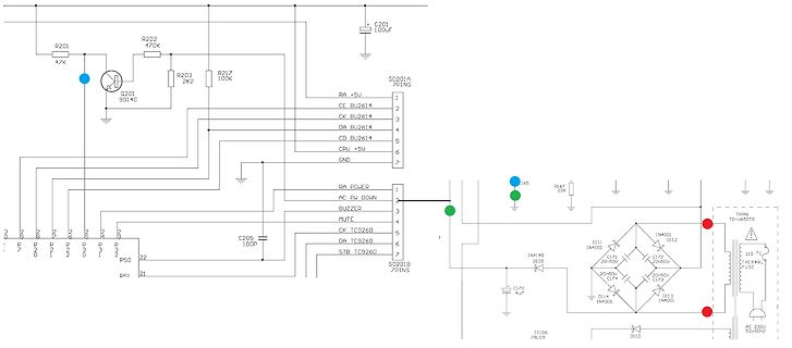
Schaltplan eines elektronischen Geräts
TC9260, DA TC9260, STB TC9260, SO201B 7PINS, C205 100P, IC106, DI11 1N4001, DI12 1N4001, DI13 1N4001, DI14 1N4001, C171 20+50V, C172 50/50V, C173, C174 4uF, C170, TRANSFORMER TC-4405TR, 110V, THERMAL FUSE, AC 230V 50/60HZ
-
Thread
KiCad 10.0 ist Erschienen.
eine 9.0.9 geben. https://gitlab.com/kicad/code/kicad/-/commit/bd24029f6ad21e392774caab9bc6fd557930ac14 https://gitlab.com/kicad/code/kicad/-/commit/ffa8fef0d39b5fe01c771b2e896ab9e89f79ec1d https://gitlab.com/kicad/code/kicad/-/commit/32b219fe66c8f149e843015349a8b3a5e2e14626 Die Hauptarbeit läuft
-
Thread
Radio Grundig sonoclock 690 - schaltet sich aus
: 2,7V => waren im DC Messbereich, 5,3V im AC Messbereich schaut mich ned so schlecht an ...
zu sehen, ob das Signal am µC Pin dem erwarteten entspricht. Derzeit vermute ich, dass die Leitung "AC PW" nicht nur das Signal "AC vorhanden" liefert, sondern auch den 50Hz Netz Sinus zum sychronisieren der Uhr liefert ...
-
Thread
Picoamperemeter Elektor
machen. Und die 330 pF viel kleiner. Aber das hängt ja auch davon ab, ob man (nur) DC oder auch AC messen will. Mit 1 GOhm bekommt man also 10exp9[V/A] x 1 exp12[A] 1 mV je 1 pA heraus. Wenn man den Offset vorher gründlich abgleicht, okay. Dann könnte man 10 pA schon einigermaßen genau messen.
topic/567224#new 30.04.2024 17:30 https://www.mikrocontroller.net/topic/564549#new 11.02.2024 14:41 https://www.mikrocontroller.net/topic/555198#new 06.06.2023 10:47 https://www.mikrocontroller.net/topic/555240#new 07.06.2023 10:37
-
Thread
Treppenlichtautomat Eltaco ER61-UC
mehr oder weniger machen IMHO den Kohl nicht fett. Ich hätte eher sowas in der Richtung wie ABB 12 V AC ABB ESB20-20N-14 mit 12V Spulenspannung genommen. Dann hätte man das im Verteilerkasten "feuchtesicher" auf Hutschiene noch montieren können. Das ER61-US bekommt seine Versorgungsspannung auch wie die
den vielen VDRS, Transistoren und Mosfet dient IMHO dazu, den Triggerspannungsbereich von 8-230V DC/AC hinzubiegen. ciao gustav
-
 Bild
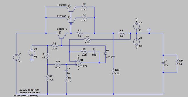
Schaltplan einer Transistor-Endstufe mit Operationsverstärker
TIP3055 Q3 R3 0.22 TIP3055 Q2 0.22 BD139_C Q1 R1 20 R8 4.7k R7 0.2 R2 0.22 V2 +12 12 V3 -12 12 C3 47u R14 10 R5 2.2k C1 82p D1 1N4148 R13 4.7k U1 TL071 C2 1n R10 4.7k R11 50k R9 1k V4 32 V5 7.5 .include TL071.301 .include UA741.301 .ac dec 50 0.10 100Meg
-
 Bild
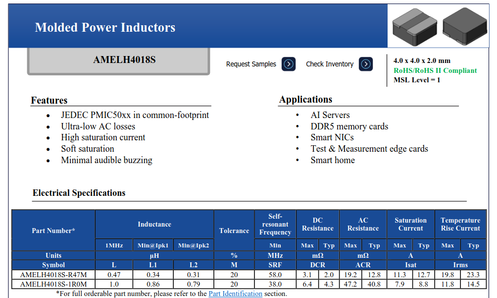
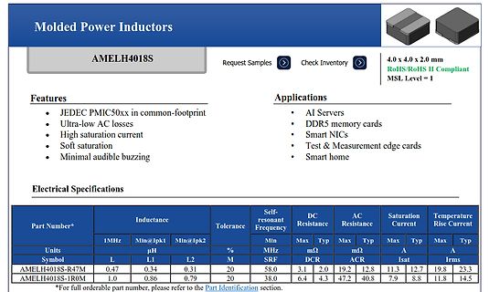
Datenblatt für gegossene Leistungsinduktoren
Molded Power Inductors AMELH4018S Features JEDEC PMIC50xx in common-footprint Ultra-low AC losses High saturation current Soft saturation Minimal audible buzzing Applications AI Servers DDR5 memory cards Smart NICs Test & Measurement edge cards Smart home Electrical Specifications Part Number
-
 Bild
MediaWiki interner Fehler
Lesezeichen-Menü MediaWiki internal error. Original exception: [fcef1bf902a4aaea4ac99a0f] 2026-03-14 10:04:40: Fatal exception of type "mysqli_sql_exception" Exception caught inside exception handler. Set $wgShowExceptionDetails = true; at the bottom of LocalSettings.php to show detailed
-
Thread
DCF77 Empfangsprobleme
Ausstrahlung des DUT-Codes mit Einführung der Übernahme der Meteotime-Daten innerhalb der ersten (14) Sekunden weggefallen ist, sendet MSF60 diese "Abweichungen zur tatsächlichen Erdrotationszeit" immer noch. In der Dateianlage sind die beiden Codierungen gegenübergestellt. MSF60 hat A und B-Code.
Reset nicht als I/O mißbraucht wird). Ersetze ihn durch einen ATtiny24 oder ähnlichen (mindestens-)14-Pinner, und schon läuft PeDas Programm nach geringfügigen Anpassungen ohne jegliche Schieberegister.
-
Thread
Feelin XR Pro Vape Podsystem Teardown
DISSET5 - Display function control spi_write_byte(DATA, 0x19); spi_write_byte(CMD, 0xAC); spi_write_byte(DATA, 0xDB); spi_write_byte(CMD, 0xAB); spi_write_byte(DATA, 0x0F); spi_write_byte(CMD, 0x3A); // COLMOD - Pixel format spi_write_byte(DATA, 0x05); /
spi_write_byte(DATA, 0x00); // ← Sonderfall: mov r0,r1 bei 0x364A spi_write_byte(DATA, 0x14); spi_write_byte(DATA, 0x0A); spi_write_byte(DATA, 0x16); spi_write_byte(DATA, 0x10); spi_write_byte(DATA, 0x1F); // === 5. GAMMA NEGATIV (0xF1) — 14 Bytes === spi_write_byte
-
Thread
Isolierte Spannungsversorgung
die blumige Aussage: "We also observed that the lifetime of iCoupler devices under dc or unipolar ac is much longer compared to that under bipolar ac; it is at least two orders of magnitude higher." https://www.analog.com/media/en/technical-documentation/technical-articles/inside_icoupler_technology_high_voltage_endurance.pdf
interessant zu lesen. Der Wandler hat eine hochgerechnete Lebensdauer von 2200 Jahren, wenn man 1200V AC bei 150°C anlegt! Nach VDE Sicherheitsauflagen werden daraus immerhin noch 1184 Jahre bei 1000V AC. Und Lebensdauer heißt nicht, daß dann plötzlich alle Wandler ausfallen, sondern eine Ausfallrate
-
Thread
Der Zugriff auf das Wiki ist SEHR langsam
Exception. [pre] MediaWiki internal error. Original exception: [5c8005d89c284ba920fba11b] 2026-04-20 14:24:19: Fatal exception of type "mysqli_sql_exception" Exception caught inside exception handler. Set $wgShowExceptionDetails = true; at the bottom of LocalSettings.php to show detailed debugging
Heute geht gar nichts mehr: [code] MediaWiki internal error. Original exception: [6212f1fc18ac2c5e69442207] 2026-06-04 08:57:54: Fatal exception of type "mysqli_sql_exception" Exception caught inside exception handler. Set $wgShowExceptionDetails = true; at the bottom of LocalSettings.php
-
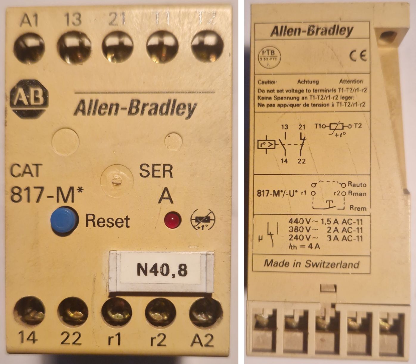
 Bild
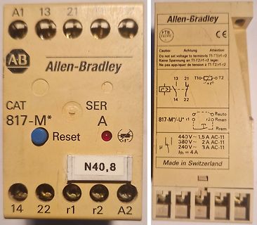
Allen-Bradley Schutzschalter / Relaismodul
r2 Keine Spannung an T1-T2/r1-r2 Ne pas appliquer de tension à T1-T2/r1-r2 13 21 T10- T2 r- T2 +r° 14 22 Rman r1 817-M*/-U* r1 r2 Rman Trem 440 V~ 1,5 A AC-11 380 V~ 2 A AC-11 μ 240 V~ 3 A AC-11 th = 4 A Made in Switzerland 14 22 r1 r2 A2 N40,8
-
Thread
Mini Loopantenne mit NE592N14
Hobby B. schrieb im Beitrag #8018992: > Interessant in der Schaltung ist der NE592N14 ( Video Verstärker ). Rauschgenerator.
Selbst die NE592N im DIP14 Gehäuse reichen noch eine Weile https://www.oemsecrets.com/compare/ne592n
-
Thread
C mit Visual Studio Code
installiert. Ich nutze folgende Linux-Version: Ubuntu 25.10 Kernel: Linux 6.17.0-14-generic Architecture: x86-64
vorletzte, das vorvorletzte... you get the idea. HF! :-) [1] https://gist.github.com/tuxfight3r/60051ac67c5f0445efee
-
Thread
Funkschlüssel Peugeot Partner I
ffffffffffffffffffffff5a6aac477cdb97b130fb602d355623be6dcbd8987db ffffffffffffffffffffff5a6a83584b55e60ce14b202d3541ac25aaf30670a59 ffffffffffffffffffffff5a6a8107b8e03e713040e02d354083dc701f3898207 ffffffffffffffffffffff5a6aacd7886c7864728ca02d35566bc4363c3239464 ffffffffffffffffffffff5a6a827db1d726029bc9e02d35413ed8eb93014de4e
Hex-Zeichen fffffffffffffffffffff122aa8b1062c66f22c77bf8915545883163379163bc fffffffffffffffffffff122a90f14ba9595a05aabf89154878a5d4acad02d54 fffffffffffffffffffff122adcebc15f190e0f583f89156e75e0af8c8707ac0 fffffffffffffffffffff122abbb214729ef5be293f89155dd90a394f7adf148 fffffffffffffffffffff122aaa75486f0b36e234bf8915553aa437859b711a4
-
Thread
Aktiver PA Lautsprecher flüstert nur noch
Die erste Messung wäre, ob das Tonsignal vom Eingang bis C14 im Schaltplan kommt. Zweite Messung, ob am Endstufenausgang ohne Ton eine Spannung gegenüber Masse zu messen ist. Eine Messung im DC-Msssbereich und eine Messung im AC-Messbereich.
LineIn und Mic abgreifen. Zur zweiten Messung: Über den Lautsprecherausgang gemessen 0V DC und 0,1V AC. Gemessen gegen Masse der Endstufe (Ausgang V1) 51,2V DC an beiden Terminals des LS und AC laut Multimeter 0,2V
-
 Bild
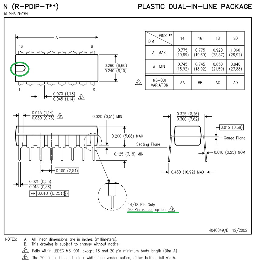
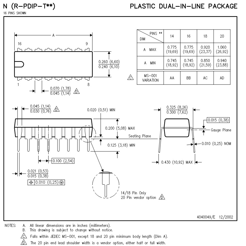
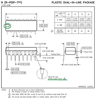
Technische Zeichnung eines Plastic Dual-In-Line Package
PLASTIC DUAL-IN-LINE PACKAGE 16 PINS SHOWN A 9 16 1 8 0.260 (6,60) 0.240 (6,10) 0.070 (1,78) 0.045 (1,14) PINS ** 14 16 18 20 DIM A MAX 0.775 (19,69) 0.775 (19,69) 0.920 (23,37) 1.060 (26,92) A MIN 0.745 (18,92) 0.745 (18,92) 0.850 (21,59) 0.940 (23,88) MS-001 VARIATION AA BB AC AD 0.045 (1,14) 0.030 (0,76
-
 Bild
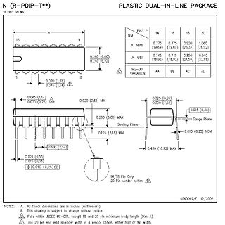
Technische Zeichnung eines Plastic Dual-In-Line Package
N (R-PDIP-T**) PLASTIC DUAL-IN-LINE PACKAGE 16 PINS SHOWN PINS ** 14 16 18 20 DIM A MAX 0.775 (19,69) 0.775 (19,69) 0.920 (23,37) 1.060 (26,92) A MIN 0.745 (18,92) 0.745 (18,92) 0.850 (21,59) 0.940 (23,88) MS-001 VARIATION AA BB AC AD 16 1 8 0.260 (6,60) 0.240 (6,10) 0.045 (1,14) 0.045 (1,14) 0.030 (0,76) 0.045 (1,14) 0.020 (0,51) MIN 0.200 (5,08) MAX 0.325 (8,26) 0.300 (7,62) 0.015 (0,38) Gauge Plane 0.125 (3,18) MIN Seating Plane 0.010 (0,25) NOM 0.100 (2,54) 0.430 (10,92)
-
 Bild
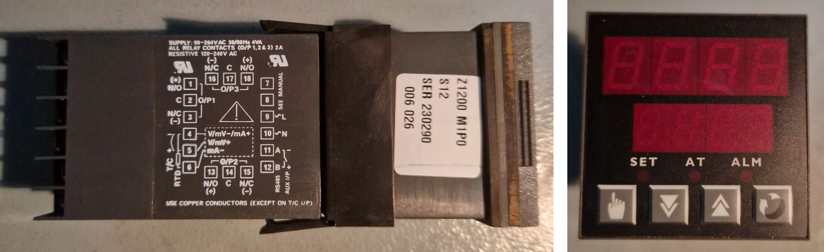
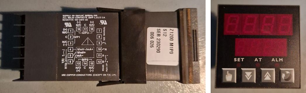
Industrie-Temperaturregler mit Display und Anschlussbelegung
SUPPLY: 90-254VAC 50/60Hz 4VA ALL RELAY CONTACTS (O/P 1,2 & 3) 2A RESISTIVE 10-240V AC (-) N/C 16 17 N/O O/P1 N/O 2 C O/P2 N/C 13 14 15 N/O O/P3 SER 230290 S12 Z1200 M1P0 006 026 SET AT ALM
-
 Bild
Elektrische Anschlüsse an einem Leistungsmodul mit rotem Text
80A @ 24V, 2000W Load ???

-
Thread
SMD Diode identifizieren
Dieter W. schrieb im Beitrag #8012034: > Je nach Gehäusegröße kann es eine SS14, SS24 oder SS34 von Vishay / > General Semiconductor sein. Danke soweit schonmal. Hier noch die Abmessungen: 2,65mm breit 4,20mm lang 2,15mm hoch Das scheint dann ein DO-214AC Gehäuse zu
Mike M. schrieb im Beitrag #8012044: > Das scheint dann ein DO-214AC Gehäuse zu sein. > Ist dann 1A, oder? Ja, ist eine SS14 von Vishay, 1A/40V Schottkydiode in Baugröße SMA.
-
Thread
[V] AC/DC Konverter Mornsun LD20-26B24
aufgerufen, die gängigen Bauteilsuchmaschinen spucken immer mal wieder 20-25 Euro aus. Ich dachte an 14,- pro Stück, es sind 6 davon verfügbar. Versand wie gewohnt separat, Bezahlung via PayPal wie immer.
#8011374: > die gängigen Bauteilsuchmaschinen spucken immer mal wieder 20-25 Euro > aus. Ich dachte an 14,- pro Stück, es sind 6 davon verfügbar. In leicht anderer Bauform, aber 24 Volt / 833mA: Aktuell Pollin Nr: 353255, MORNSUN AC/DC Wandler LD20-23B24R2, 1,95€ Butzo*aussen
-
 Bild
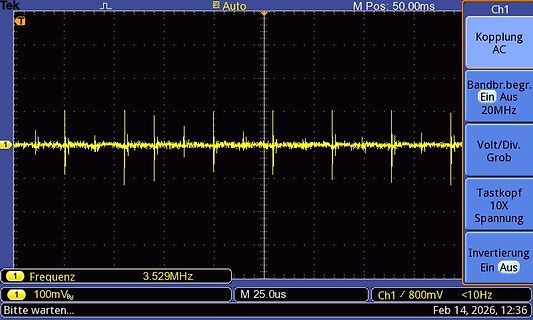
Oszilloskop-Messung eines Signals mit Impulsen
Tek Auto M Pos: 50.00ms Ch1 Kopplung AC Bandbr.begr. Ein Aus 20MHz Volt/Div. Grob Tastkopf 10X Spannung Invertierung Aus 1 Frequenz 3.529MHz M 25.0us Ch1 / 800mV <10Hz Bitte warten... Feb 14, 2026, 12:36
-
Thread
[V] uC, Digtal, Analog, Transistoren, Evalboards
CMR200T32768DZFT, Citizen: 32.768KHz 12.5pF -> 0,05€/Stk. 2700x SMD03025/4 12MHz 30/50ppm 14p, TJE -> 0,05€/Stk. 750x SMD03025/4 12MHz 30/30ppm 14p, TJE -> 0,05€/Stk. 500x SMD03025/4 26MHz 30/50ppm 8p, TJE -> 0,05€/Stk. 250x DSX321G
0,15€/Stk. 52x 0525030.MXEP, Littelfuse: 30A 450VDC Axial -> 0,15€/Stk. Relais: 14x HE722A1200, Hamlin: 12V-Reed doppelter Schliesser -> 0,50€/Stk. 40x V23057-B0002-A101, Schrack: 12V Wechsler, 400VAC, 5A -> 2,00€/Stk. 8x LYCA024V, FCL: 6A, 250V AC
-
Thread
Neue Bauteile: Passives, Spannungsmanagement und MPUs
einem Ausgangspin Leistung für externe Schaltungen bereitstellt. [/c] ### Microchip MCP6C26 – nun AEC Q100-zertifiziert Wer einen mit der INA210/1/2/3/4/5-Familie kompatiblen Strommeßverstärker benötigt und von AEC-Zertifikation profitiert, wird von Microchip mit einer „Aktualisierung“ eines eigentlich
> Microchip MCP14T0517 - Transformatortreiber für galvanisch isolierte > Stromversorgungen. Hmm, warum bauen die einen weiteren ungeregelten Treiber, in der Form gibts das doch schon oder ist sogar auch mit nem 74HC14
-
Thread
Chroma 19052 Hochspannungsstecker gesucht
Bananenstecker vorn anlöten und mit Heißkleber stabilisieren. Fertig ist der HV Stecker. Sind ja nur 5kV AC. Die Stecker gibt es als Löt- bzw. Schraubversion für eine handvoll Euro.
Interesse an der Reparatur hat: https://www.eevblog.com/forum/repair/repair-and-review-of-chroma-19052-ac-dc-hipot-tester/
-
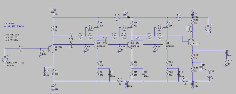
 Bild
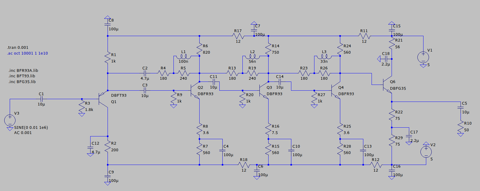
Schaltplan einer Transistorstufe mit Induktivitäten
.tran 0.001 .ac 10001 1 1e10 .inc BFR93A.lib .inc BFT35.lib C1 10µ V3 SINE(0 0.01 1e6) R3 1.8k Q1 DBF93 C12 C9 100µ R2 200 C2 4.7µ R4 180 R5 240 L1 100n C11 10µ R13 180 R17 12 Q2 DBFR93 R8 3.6 R7 560 C4 100µ R16 7.5 R15 560 C10 100µ R18 12 C6 100µ L2 56n R19 240 Q3 DBFR93 R20 1k R27 1k R23 180 R26 180 L3 33n C14 10µ R24 12 R11 C15 100µ R21 56 C18 2.2µ Q4 DBFR93 R25 3.6 R28 560 C13 100µ R12 12 C16 100µ Q6 DBFG35 R22 75 R29 75 C17 2.2µ C5 10µ R10 50 V2 5