- o m c O N F R D I A C C C E I P ( T P EFM8UB20F64G-B-QFP48 64 4352 40 32 5 5 Yes Yes Yes -40 to +85 °CQFP48 EFM8UB20F64G-B-QFP32 64 4352 25 20 5 4 — — Yes -40 to +85 °CQFP32 EFM8UB20F64G-B-QFN32 64 4352 25 20 5 4 — — Yes -40 to +85 °CQFN32 EFM8UB20F32G-B-QFP48 32 2304 40 32 5 5 Yes Yes Yes -40 to +85 °CQFP48 EFM8UB20F32G-B-QFP32 32 2304 25 20 5 4 — — Yes -40 to +85 °CQFP32 EFM8UB20F32G-B-QFN32 32 2304 25 20 5 4 — — Yes -40 to +85 °CQFN32 silabs.com | Smart. Connected. Energy-friendly. Rev. 1.3 |
I O 0 2.7 V 4 8 1.65 V 2 4 5.5 V 0.2 2 CC VI= GND (3,OI = 0, -40 ℃ ≤ A ≤ 3.6 V 0.1 2 μA Low inputs 85 ℃ 2.7 V 0.1 1 1.65 V 0.1 1 5.5 V 0.2 2 Standby mode VI= V CC,OI = 0, -40 ℃ ≤ A ≤ 3.6 V 0.1 2 High inputs 85 ℃ 2.7 V 0.1 1 1.65 V 0.1 1 3.6 V 1 2 Low and High VI= V CCor GND, IO= 0, 85 ℃ < Inputs T ≤
of the sensors is unlimited, provided the sensors are stored at a maximum of 30 °C and a maximum of 85% relative humidity. At these conditions, no Dry Pack is required. Solderability is guaranteed for one year from the date code on the package. 12 Micronas DATA SHEET HAL300 3.5. Recommended Operating
PCMCIA cards. The thermal resistance and power dissipation are the best available. Standard Pack Base Part Number Package Type Orderable Part Number Form Quantity IRLML2502TRPbF Micro3™ (SOT-23) Tape and Reel 3000 IRLML2502TRPbF Absolute Maximum Ratings Parameter Max. Units VDS Drain- Source Voltage
.................................. 83 Test the TOW Predefined Function ........................... 85 ConfigureCountdown(CTD) ................................ 87 TesttheCTDPredefinedFunction............................ 88 ConfigureTONOFF ......................................... 90 TesttheTONOFFPredefinedFunction
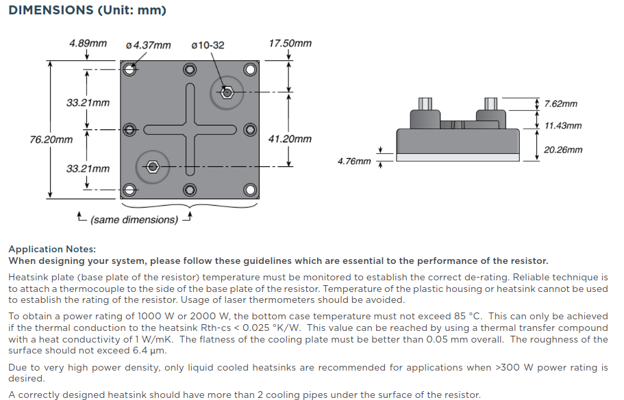
please follow these guidelines which are essential to the performance of the resistor.
Heatsink plate (base plate of the resistor) temperature must be monitored to establish the correct de-rating. Reliable technique is to attach a thermocouple to the side of the base plate of the resistor. Temperature of
1. 2. Remove the Front Panel ASS’Y, referring to the previous step 2. 3.. Disconnect connector (CN85)on the Phone PCB (37-5) from the lead wire (BN85-2P) on the FIP PCB (37-1). 4. Remove 2 screws (S2) and then remove the Phone PCB (37-5). 5 POWER LED PCB (37-3) REMOVAL 1. Remove the Top-cabinet, referring
Unit Conditions Operating supply voltage VCC 4.0 − 6.0 V Pin8,12 Operating temperature Topr −40 − +85 °C Audio input level V IN-A − − −10 dBV Pin1,22 Audio input frequency band IN-A 20 − 15k Hz Pin1,22 Pre-emphasis time constant set up ranget PRE − − 155 µsec Pin2,21 Transmission frequency fTX 70 − 120
/AFG V IN= 3.85 V ⎯ 0.93 1.35 IIN (ON) 2 V IN= 5 V ⎯ 0.35 0.5 mA Input current TD62084APG/AFG V IN= 12 V ⎯ 1.0 1.45 IIN (OFF) 4 IOUT = 500 μA, Ta = 85°C 50 65 ⎯ μA V CE= 2 V,OUT = 200 mA ⎯ ⎯ 2.4 TD62083APG/AFG V CE=
current (any pin except supplies) ±10 mA Power dissipation 300 mW Operating temperature range –25°C to 85°C Storage temperature –55°C to 125°C Lead temperature, soldering 260°C, 5 s Package temperature (IR reflow, peak) 235°C RECOMMENDED OPERATING CONDITIONS over operating free-air temperature range MIN
die CPU erzeugte dann Phi2 (siehe z.B. http://retro.hansotten.nl/6502-sbc/elektuur-junior/junior/base-elektor-junior/) Gruesse P.S.: Gucke bitte in das Datenblatt: [code] 3.8 Phase 2 In (PHI2), Phase 2 Out (PHI2O) and Phase 1 Out (PHI1O) Phase 2 In (PHI2) is the system clock input to
Zeiten. Spannend fand ich den Inset bei p.25, Fig 6-2 dass wohl WDC die maximale Frequenz bei 85°C bestimmt. Das ist schon ganz schoen warm fuer Halbleiter. Und eine Sache muss man sehen (bei den Grafiken 6-1 und 6-2): "Typical 0.6u processed device" heisst "Our best device". Ist ja nicht gewaehrleistet
located in Wenzhou City, Zhejiang Province. At present, the company has 40K sqm of modern manufacturing bases in Wenzhou and Wuhu with over 500 employees, including over 50 R&D and technical personnel. ETEK Electric has multiple production workshops for mold design, parts manufacturing, welding, and assembly
RATINGS DESCRIPTION SYMBOL BD433 BD435 BD437 BD439 BD441 UNIT BD434 BD436 BD438 BD440 BD442 Collector Base Voltage V CBO 22 32 45 60 80 V Collector Emitter Voltage V CES 22 32 45 60 80 V Collector Emitter Voltage V CEO 22 32 45 60 80 V Emitter Base Voltage V EBO 5.0 V Collector Current C 4.0 A Collector
5) Pas d’action Menu Retour au menu Pas d’action Décalage de la courbe de chauffage vers le bas (plus Faire défiler les différentes options d’un niveau et froid) descendre vers la dernière Modification de la consigne de température ambiante, de Modifier une valeur de réglage vers le bas
antifreeze if heat pump systems are implemented in buildings tors. Use the plug connector located on the base of the heat where a power failure can not be detected (holiday home). pump adjacent to the cable gland in the base plate. More de- tailed information can be found in the operating instructions of the
Source V = V = 1V, comp1_SC FB1_FIX FB2_FIX 6 127 comp2_SC Current VCOMP1 = V COMP2 = 1V µA -20°C to 85°C 18 comp1_SK, COMP Output Sink Current VFB1_FIX= VFB2_FIX= 1.5V and comp2_SK VCOMP1 = V COMP2 = 0.5V 6 118 µA -20°C to 85°C 18 gm1, gm2 Transconductance 720 µmho GI , Current Sense Amplifier V = 1.25V
rating Tol. Pack-Code TCR Forming type R Value Special Power & Energy Computer & J = ±5% T = Tape - Base on52- Inner Taping UL = UL Version Peripherals (ammo pack) spec. dimension or YY = Standard 73- Inner Taping Automotive dimension ZB- Z version Historical VTM Part Nr.: CRF254 – 8 5 T 150R Precision
Collector-emitter VoltageBEV= 0) 32 45 V V CEO Collector-emitter VoltagB (I = 0) 32 45 V V EBO Emitter-base Voltage CI= 0) 7 V C Collector Current 200 mA I Base Current 50 mA B Ptot Total Power Dissipation atamb 25 ⋅C 0.39 mW at Tcase 45 ⋅C 1 W T stg Tj Storage and Junction Temperature – 65 to 200 ⋅C January
scope at /home/christoph/Entwicklung/Modell/modelJulia.jl:15 [2] include(::Module, ::String) at ./Base.jl:377 [3] exec_options(::Base.JLOptions) at ./client.jl:288 [4] _start() at ./client.jl:484 in expression starting at /home/christoph/Entwicklung/Modell/modelJulia.jl:15 [/c] Hast Du einen
noch eine Rolle spielen. [code] laengeFuss=96; zPosAchse=27; // Schraubenloecher lochAbstand=85; [/code]
Capacitor Radial Electrolytic Dia 40mm PCB Mount 10000uF 71V D101 3AS16W Diode Surface Mount Small Signal BAS16W SOT-23 Package D200 3AS16W Diode Surface Mount Small Signal BAS16W SOT-23 Package D201 3AS16W Diode Surface Mount Small Signal BAS16W SOT-23 Package D202 3AS16W Diode Surface Mount Small Signal BAS16W
Ambienttemperatureoperation(°C) 55 55 55 55 55 55 55 55 55 m r n Ambienttemp. duringstorage/transport(°C) -40 to 85 -40 to 85 -40 to 85 -40 to 85 -40 to 85 -40 to 85 -40 to 85 -40 to 85 -40 to 85 E e IP Class 20 20 20 20 20 20 20 20 20 s l n E Weight (kg) 0.27 0.34 0.28 0.32 0.31 0.31 0.26 0.26 0.43 Connectors (6.3
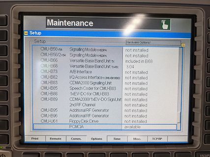
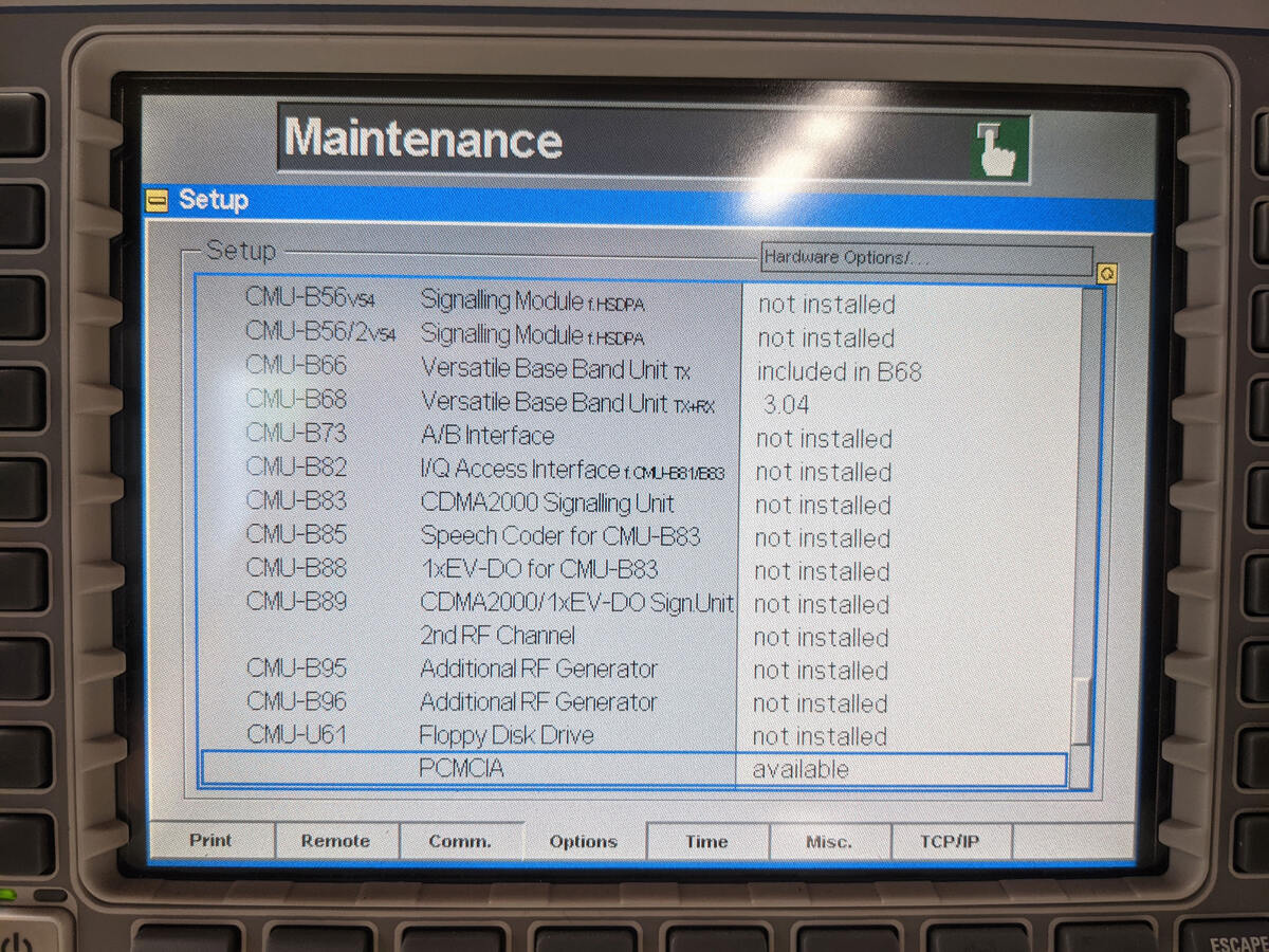
Module 1xHSDPA not installed
CMU-B56/2v54 Signalling Module 1xHSDPA not installed
CMU-B66 Versatile Base Band Unit Tx included in B68
CMU-B68 Versatile Base Band Unit Tx/Rx 3.04
CMU-B73 A/B Interface not installed
CMU-B82 I/Q Access Interface not installed
CMU-B83 CDMA2000 Signalling Unit not installed
CMU-B85 Speech Coder for CMU-B83 not installed
CMU-B88 1xEV-DO for CMU-B83 not installed
CMU-B89 CDMA2000/1xEV-DO Sign.Unit not installed
CMU-B95 2nd RF Channel not installed
CMU-B96 Additional RF Generator
0.22 dB/m typical attenuation • Every plastic fiber with an external diameter of 2.2 mm (-40°C to 85°C) and an internal diameter of 1 mm can be used - High performance Extra Low Loss POF with 0.19 dB/m • Small housing dimensions typical attenuation (-40°C to 85°C) • The housing protects photodetectors
Memory The category is display-only which is determined by POST (Power On Self Test) of the BIOS. Base Memory The POST of the BIOS will determine the amount of base (or conventional) memory installed in the system. The value of the base memory is typically 512 K for systems with 512 K memory installed
L quotas and slack. Wear = W We first refine the policy by dividing B for the remaining life into base bandwidth (B) and slack bytes (S). We set S at 50% ofW For example, we can calculate the wear induced by the “Final Fan- by default, which reduced B to B = 0.73 MiB/s. Once the apps have tasy” app (
°C to +70°C Fully Compliant with IEEE 802.3/802.3u Stan- • Industrial Temperature Range: –40°C to +85°C dards • Available in 32-pin (5 mm x 5 mm) QFN Package • SPI with Clock Speeds up to 40 MHz for High Additional Features Throughput Applications • Supports 10BASE-T/100BASE-TX In addition to offering
59 4 Vendor rev Revision level for part number provided by vendor (ASCII) 60-62 3 Reserved 63 1 CC_BASE Check code for Base ID Fields (addresses 0 to 62) EXTENDED ID FIELDS Options Indicates which optional SFP signals are implemented 64-65 2 (see Table 3.6) 66 1 BR, max Upper bit rate margin, units of
automatisch installiert, ab minute 2. Vielleicht gibt es das noch. https://www.youtube.com/watch?v=1zNWX85wa8Y Abtippen musste selber :P
installiert, ab minute 2. > Vielleicht gibt es das noch. > https://www.youtube.com/watch?v=1zNWX85wa8Y > Abtippen musste selber :P Ja, das Script kenne ich, schon durchprobiert. Bin zwischenzeitlich auf eine Bemerkung vom Autor gestoßen, wo er bemerkt, dass er seine Software auf einem 64bit System
0.60 mm supply, the Bulk Cases are re- moved and replaced outside the Chip 0805 component height 0.85 mm machine eliminating stoppages for Chip 0805 component height 1.25 mm replenishment. Mini-Melf Feeder location 1 feeder location for 2 different Essentially, this feeder module consists of a base which
Green-Mode PWM Controller Integrated with Power BJT iW1817 Output Power Table at Universal Input (85V –264V AC AC Condition Open Frame 2 Output Power (W) 7.0 Notes: 1. Maximum practical continuous output power measured at open frame ambient temperture of 50°C and device pins/ package temperatures of
Considerations: ● 10/100/1000 relates to the data rate in Mbps (i.e. 10Mbps, 100Mbps, and 1000Mbps) •For 10 Base-T, data is transmitted over 2 UTP (unshielded twisted pairs) using a 10MHz clock •For 100 Base-TX, data is transmitted over 2 UTP using a 125MHz clock •For 1000 Base-T data is transmitted over 4 UTP
VCC 0 3.6 Vdc CPx, Reset, Data In, Data Out VoltagVCP -0.3 V CC+0.05 Vdc Operating Temperature -40 85 oC o Storage Temperature -40 85 C Table 2-5 Recommended Operating Conditions Parameter Symbol Min Typical Max Units Supply Voltage VCC 3.15 3.3 3.46 Vdc Supply Voltage Ripples VCC_PP 2 % 100Base-TX Active
avlcišdiavroprezbl: aatritcequeste lcl mento ě nuovaelig.oini. MI sembrltocico,cnidrndocheoschema base lsio, muaie, lclre oi aoi i eitne,dopovrprvto elinqusine. E'iero uo,e questo pub sar.e b figure5 el Schema di principio sirena cvedi testo.ettronicamente Irlissono Gel3112, enunine le oo resini o rgetto
VCC Supply voltage 2.6 4.5 V VI/O Input/Output voltage 0 5.5 V T Operating free-air temperature –40 85 °C A (1) All unused control inputs of the device must be held at VDD or GND to ensure proper device operation. Refer to the TI application report, Implications of Slow or Floating CMOS Inputs, literature
auf digitale Übertragung umgestellt. Ungeschickterweise gibt es dafür auch die Typenbezeichnung CS85, sodaß eine Suche nach dem Original schwierig ist. https://www.elro.eu/de/ https://de.elv.com/elro-digitales-kamerasystem-mit-monitor-102985 Ich nehme an, das funkt auf 2,4 GHz in analogem FM-TV
Signale empfangen kann. Meines Erachtens kannst du den Empfänger ausbauen. Er dürfte einen (F)-BAS Ausgang haben, der irgendwo auf das TV-Chassis geht. Den abtrennen und nach außen führen. Vermutlich haben die meisten Hersteller solcher Funksysteme (ich war in den 90ern einer davon), die Fernseher
ELECHOUSE_cc1101.setDeviation(47.60); // Set the Frequency deviation in kHz. Value from 1.58 to 380.85. Default is 47.60 kHz. ELECHOUSE_cc1101.setChannel(0); // Set the Channelnumber from 0 to 255. Default is cahnnel 0. ELECHOUSE_cc1101.setChsp(199.95); // The channel spacing is multiplied by the channel number CHAN and added to the base frequency in kHz. Value from 25.39 to 405.45. Default is 199.95 kHz. ELECHOUSE_cc1101.setRxBW(812.50); // Set the Receive Bandwidth in kHz. Value from 58.03 to 812.50. Default is 812.50 kHz
LINEAR AND SWITCHING INDUSTRIAL 1 EQUIPMENT TO-220 DESCRIPTION The BDX53F is a silicon Epitaxial-Base NPN power transistor in monolithic Darlington configuration, mounted in Jedec TO-220 plastic package. It is intented for use in power linear and switching applications. The complementary PNP type is
°C to 85°C................372...... 30.3 ATmega324A typical characteristics - TA = -40°C to 85°C ................398........ 30.4 ATmega324PA typical characteristics - TA = -40°C to 85°C................424...... 30.5 ATmega644A typical characteristics - TA = -40°C to 85°C ................450........ 30.6 ATmega644PA typical characteristics - TA = -40°C to 85°C................476...... 30.7 ATmega1284 typical characteristics - TA = -40°C to 85°C.................502..
USB cables to others boards •5.0 V and 9.0 V power supplies DesignCon 2003 TecForum I C Bus Overview 85 Slide 85 29 AN10216-01 I C Manual 2 Slide 85 discusses the devices on the I2C 2002-1A 2 How to program the Universal Screen? evaluation board that is not controlled via the I C bus. They just provide
Microcontroller 7. Peripherals and Architecture 7.1 Peripheral Module Address Map The address map show the base address for each peripheral. For complete register description and summary for each peripheral module, refer to the respective module chapters. Table 7-1. Peripheral Module Address Map Base Address
Architecture 8. Peripherals and Architecture 8.1 Peripheral Address Map The address map shows the base address for each peripheral. For complete register description and summary for each peripheral, refer to the respective peripheral sections. Table 8-1. Peripheral Address Map Base 28- 32- 48- 64- Address

 Bild
Bild
 Bild
Bild