EC 60 ∅60 mm, bürstenlos, 400 Watt, approved r o t o m C E n o x a m M 1:4 Lagerprogramm Bestellnummern Standardprogramm Sonderprogramm (auf Anfrage) 167132 167131 Motordaten Werte bei Nennspannung 1 Nennspannung V 48.0 48.0 2 Leerlaufdrehzahl min -1 5370 3100 3 Leerlaufstrom mA 733 304 4 Nenndrehzahl min -1 4960 2680 5 Nennmoment (max. Dauerdrehmoment) mNm 747 830 6 Nennstrom (max.Dauerbelastungsstrom) A 9.38 5.85 7 Anhaltemoment mNm 11800 6820 8 Anlaufstrom A 139 46.4 9 Max.Wirkungsgrad
CORDIC For Dummies CORDIC is a method of calculating a math function using much simpler math operations in a loop called a Binary Search. Most commonly CORDIC is used to calculate ATAN2 (Angle), and Hypotenuse (Distance) of a point
the time taken for the sensor to reach 63.2% of the total temperature difference. For example, if a sensor with a temperature of 25 °C is moved to an environment with an ambient temperature of 100 °C, the time for the sensor to reach a temperature of 47.4 °C is the thermal time constant. 2. Inert liquid
320 to 1000 - nm Peak sensitivity wavelength λp - 760 - nm Photo sensitivity S λ =405 nm 0.26 0.3 - A/W Dark current ID V =2.5 V - 0.01 0.3 nA V =2.5 V, R =50 Ω Cut-off frequency fc λ=405 nm, -3 dB 300 500 - MHz Terminal capacitance Ct V =2.5 V, f=1 MHz - 6 12 pF 1 Si PIN photodiode S9687 ■ Spectral response ■ Dark current vs. reverse voltage (Typ. Ta=25 ˚C) (Typ. Ta=25 ˚C) 0.6 1 nA QE=100 % ) 0.5 W A 100 pA ( 0.4 T T N V R T R S 0.3 U 10 pA N C S R A T 0.2 D O 1 pA P 0.1 0 100 fA 200 400 600 800 1000 1200 0.01 0.1 1 10 100 WAVELENGTH (nm) REVERSE VOLTAGE (V) KPINB0285EB KPINB0286EA
? An jeder der Röhren fallen grob 15 Volt ab. Der Strom betragt ein knappes mA. Die Steilheit beträgt dort ca. 3mA/Volt.
Arbeitspunk 1) und einen neuen 2). Laut Datenblatt sollten folgende Ströme fließen: 1) Rk=2.2k Ia=2mA Ig2=0.5mA 2) Rk=270 Ia=8mA Ig2=2mA Warum fließen an der Anode nur 3 anstatt 8mA, kann die EF85 verbraucht sein? Die Aufgabe lautet jetzt, ein Setup zu finden, das etwas lauter spielt als ohne
1300/1300 8174/203-2413-33 0,733 48 4,5 A 750 V d 41 1300/1300 8174/204-4813-33 1,401 03164E00 8174/2 Aderleitungs- 60 4,5 A 750 V d 48 1300/1300 8174/205-6013-33 1,775 durchführung 0,75 4 9 A 750 V d 34 1300/1300 8174/203-0401-33
to their optimal price/performance ratio. Sensor Construction: The temperature sensor consists of a photo-lithographically structured, high-purity plati- num coating arranged in the shape of a meander. The platinum thin film structures are laser trimmed to form resistive paths with very precisely defined basic value of the resi- stivity. The sensors are covered with a glass passivation layer; to protect the sensor against mechanical and chemical damage. The bonded leadwires which are additionally covered with a drop of glass make electrical contacts to the resistive
; (Load change: 10 ... 100% at 100 Hz; (Variation de charge: 10 ... 100% avec 100 Hz; dI/dt = 0,25 A/µs) dI/dt = 0.25 A/µs) dI/dt = 0,25 A/µs) Gesamtausregelzeit, Total control time, Temps de réponse global, < 0,8 < 0,2 < 0,1 Toleranz 1% x V 1 Nenn [ms] Tolerance 1 % x V 1 nom[ms] Tolérance 1% x V 1
D a r i u s M. schrieb im Beitrag #3955216: > ArnoR schrieb im Beitrag #3954929: >> D a r i u s M. schrieb im Beitrag #3954505: >>> Anbei eine asc zum spielen. >> >> Alter Hut: >> >> http://www.mikrocontroller.net
D a r i u s M. schrieb im Beitrag #3957938: > Max Mustermann schrieb im Beitrag #3957918: >> D a r i u s M. schrieb: >>> Ich gehe davon aus, dass sich die maximal zulässige Spannung am >>> Lautsprecher
waren nach einigen Jahren rumstehen tot. Ging aber auch ohne Schaltplan zu reparieren. Außer einem µA733 war da auch nicht viel drin.
bzw. was davon noch übrig ist. Aber auf der Rückseite steht immer noch: "D e u t s c h e Q u a l i t ä t s e i t ü b e r 5 0 J a h r e n" Aber nichts für Ungut... Mfg. Uwe H. (*bin selbst 41)
Application Tooling-pg. 67 Metallic Sleeve-Copper per ASTM B-152 Plating-Tin per ASTM B-545 s e l p S d a l a i m r e Wire Size Dimensions Terminal Wire Fits Part Numbers T Insulation Recept. Stock N Series Circular Mils Style W L Insulation Tab Loose Tape Strip O [mm 2] Nom. Max. Color Diameter Matl. Thk. Thk. Piece Mounted Form T Max. S A 22-18 .300 .900 Red .140 Brass .018 .032 640903-1* 640903-2 640902-1 F 509-1,900 B 7.62 22.86 3.56 0.46 0.81 G [0.26-0.96] .300 .900 .140 .018 .032 2 2 7.62 22.86 Red 3.56 Brass 0.46 0.81 55675-1 55675
Application Tooling-pg. 67 Metallic Sleeve-Copper per ASTM B-152 Plating-Tin per ASTM B-545 s e l p S d a l a i m r e Wire Size Dimensions Terminal Wire Fits Part Numbers T Insulation Recept. Stock N Series Circular Mils Style W L Insulation Tab Loose Tape Strip O [mm 2] Nom. Max. Color Diameter Matl. Thk. Thk. Piece Mounted Form T Max. S A 22-18 .300 .900 Red .140 Brass .018 .032 640903-1* 640903-2 640902-1 F 509-1,900 B 7.62 22.86 3.56 0.46 0.81 G [0.26-0.96] .300 .900 .140 .018 .032 2 2 7.62 22.86 Red 3.56 Brass 0.46 0.81 55675-1 55675
aktivieren (nicht invertiert), Das Bit WGM10 wird im Datenblatt auch als PWM10 bezeichnet */ TCCR1A = (1<<COM1A1)|(1<<COM1B1)|(1<<WGM10); /* Einstellen der PWM-Frequenz auf 14 kHz ( Prescaler = 1 ) */ TCCR1B = (1<<CS10); /* Interrupts für Timer1 deaktivieren Achtung : Auch die Interrupts
/*### Analogwerte ###*/ void Analogwerte(void) { //Alle internen Pullups an, ausgenommen Port A3 und Batteriespannung/Taster (A6 und A7). Da A3 aber nun auch nicht auf GND liegt, ergibt sich ein "Rauschen", der Wert variiert mit jeder Messung mehr oder weniger stark. setportaon(0); setportaon
; acc.q += ( m * (uint64_t)MAGIC_1E3_wHI ); acc.q += ( c * (uint64_t)MAGIC_1E3_wLO ); acc.a[1] += (uint32_t)( c * (uint64_t)MAGIC_1E3_wHI ); return ( acc.a[1] ); // Extract result, high-acc } [/c] Der ESP8266 Exception Stack decoded: [c] 0x40103523: lmacRecycleMPDU at ?? line
home/user/.arduino15/packages/esp8266/hardware/esp8266/2.3.0/cores/esp8266/Print.cpp line 76 0x40206a8c: printTimeTFT(unsigned int, int) at /home/user/Projects/LEDMatrix/HSG_Stopuhr/FW/ntp/ntp.ino line 639 0x40207526: updateWifi() at /home/user/Projects/LEDMatrix/HSG_Stopuhr/FW/ntp/ntp.ino line 733
Parameter C4900 C4900-01 C4900-50 C4900-51 Unit Input Voltage Range +15 ± 1 +12 ± 0.5 +15 ± 1 +12 ± 0.5 V a with no load 14 15 14 15 Input Current with full load 90 95 90 95 mA (Typ.) Variable Output Range 0 to –1250 0 to +1250 V Specification Guaranteed –200 to –1250 +200 to +1250 V Output Voltage Range Output Currentb 0.6 0.5 0.6 0.5 mA (Max.) b % (Typ.) LineRegulationagainst ±1Vor0.5VChange ± 0.01 Load Regulation against 0 % to 100 % Load Change a ± 0.01 % (Typ.) b Ripple / Noise (p-p) 0.007 % (Typ.) Output Voltage Controlling Modes
the user. exceptional performance of the - Easy to integrate best-selling ScanPlus 1800Vista™ into a very compact,industry- Integrating an OEM module has standard form factor: never been so easy. - Unique reading performance Designing a new product? The E1022 is easy to control.It The E1022 can read
die Periph auch das Startbit gesendet hat: "Setting the START bit causes the interface to generate a Start condition and to switch toMaster mode (MSL bit set) when the BUSY bit is cleared. Then the master waits for a read of the SR1 register followed by a write in the DR register with the Slave address
a. Copyright License. You grant Microsoft, and those who receive the Submission directly or > indirectly from Microsoft, a perpetual, worldwide, non-exclusive, royalty-free, irrevocable license in the
Beitrag #5703823: > Aber ich glaub irgendwie nicht mehr, das das der einzige Grund ist. > Abschnit 5.a: >> 5. Licenses. >> a. Copyright License. You grant Microsoft, and those who receive the Submission > directly or >> indirectly from Microsoft, a perpetual, worldwide, non-exclusive, royalty-free
Description 1. BOM Count 8.0 Total Design BOM count 2. Total BOM $10.672 Total BOM Cost 3. Cin IRMS 1.904 A Current Input capacitor RMS ripple current 4. Cout IRMS 102.17 m A Current Output capacitor RMS ripple current 5. IC Ipk 5.177 A Current Peak switch current in IC 6. Iin Avg 1.846 A Current Average input current 7. L Ipp 353.929 m A Current Peak-to-peak inductor ripple current 8. M1 Irms 3.007 A Current Q Iavg 9. FootPrint 846.0 mm2 General Total Foot Print Area of BOM components 10. Frequency 500.0 k Hz General Switching frequency
sensitivity Short Temp. Spectral Peak S circuit Dark coefficient Cut-off Terminal NEP response sensitivity (A/W) current current of frequency capacitance VR=10 V Type No. range wavelength Isc I I fc Ct λ λ p λ λ p λp 660 780 830 100 lx TCID f=1 MHz nm nm nm Typ. Max. (nm) (nm) (µA) (nA) (nA) (times/°C) (GHz)
gestört. Andere sind in der Lage solche Threads nicht anzuklicken und auch im Thread zu übergehen. Auch A. K. beherscht das problemlos. Wohin das im realen Leben führen kann, siehe: https://www.spiegel.de/panorama/justiz/mannheim-72-jaehrige-frau-schaltet-sauerstoffgeraet-von-bettnachbarin-im-krankenhaus-aus-a-68e76908-d024-4068-a175-733dc0a02cd8
while (getline(inFile, line)) { std::string_view line_view = line; for (std::size_t a = 0, b, i = 0; (b = line_view.find(';', a)) != std::string_view::npos; a = b + 1) { csv_entries[i++] = std::string_view(line.data() + a, b +
Seltsamerweise wird sie langsamer, wenn man statt [c] csv_entries[i++] = std::string_view(line.data() + a, b + 1 - a); [/c] die substr-Funktion verwendet: [c] csv_entries[i++] = line_view.substr(a, b + 1); [/c] bzw. ganz ohne die "a" Variable und mit remove_prefix: [c] for (std::size_t b,
michael_ schrieb im Beitrag #5485323: > Bau das mit zwei Eintakt-A Stufen auf. Ich würde es auch als Stereogerät aufbauen. Je eine ECC83 als Vorstufe + Kuhschwanz-Klangsteller und eine EL84 als 6W Endstufe.
Beethoven (Rochlitz) hatte man auch nur Kathodenwiderstände für die Gittervorspannung (Ruhestrom = 29mA).
. Variant types (S3931-01, S3932-01) with a visible-cut resin window are also available. 01 with a transparent resin window is also available.ng position detection at a long distance. S3270 has a visible-cut resin window, and S3270- Features Applications
N U O TU701 MDLK3B483A L701 L702 C D D N I TUNER/DEMODULATOR C702 47µH 15µH R721 C733 C734 G A A I L R V RF OUT R704 0.1 R716 R718 330 R723 R725 10µ 0.1 R730 R731 R733 R735 N V E E O I I . 2 910 BC R707 R710 R711 AMP 1k 150
folgende Zuordnung: Registername MD-Feature-Port Kompatibilität zu AIO386SX Memory-Page 0 Index 30 A21 - A14 Port E8h Index 31 Index 31 A23 - A22 Port EAh A21 - A14 Port EBh A23 - A22 Memory-Page 1 Index 32 A21 - A14 Port E8h Index 33 Index 33 A23 - A22 Port EAh A21 - A14 Port EBh A23 - A22 Memory-Page 2 Index 34 A21 - A14 Port E8h Index 35 Index 35 A23 - A22 Port EAh A21 - A14 Port EBh A23 - A22 Memory-Page 3 Index 36 A21 - A14 Port E8h Index 37 Index 37 A23 - A22 Port EAh A21 - A14 Port EBh A23 - A22 AIO486 Rev
folgende Zuordnung: Registername MD-Feature-Port Kompatibilität zu AIO386SX Memory-Page 0 Index 30 A21 - A14 Port E8h Index 31 Index 31 A23 - A22 Port EAh A21 - A14 Port EBh A23 - A22 Memory-Page 1 Index 32 A21 - A14 Port E8h Index 33 Index 33 A23 - A22 Port EAh A21 - A14 Port EBh A23 - A22 Memory-Page 2 Index 34 A21 - A14 Port E8h Index 35 Index 35 A23 - A22 Port EAh A21 - A14 Port EBh A23 - A22 Memory-Page 3 Index 36 A21 - A14 Port E8h Index 37 Index 37 A23 - A22 Port EAh A21 - A14 Port EBh A23 - A22 AIO486 Rev
D D2 L I02 10 Q13 R PID140D LED PIR501 I03 Q161 PO/ TW GND L D111 w D13 1 MOSFET Red 1 MOSFET GND a D0 Red LED t I0 Red LED 2 PIQ1301 P O/SDS D 2 PIQ1601 R S 12 2 I02 A GND D161 A 0 Red LED Q3 Q111 MOSFET P I Q 1 1 0 1 P OREADYA D Y Q2 GND GND GND GND CC7 7 PIC77PIC7701 150pF CR62 PIR6202PIR6201 10K
sd karte gespeichert wird. Erstmal dachte es wäre weil die Accelerometer ADC eingänge den PORT.A mit dem Schiberegister teilen, deswegen wird der Schiberegister bei jede messung gestört. Allerding auch wenn ich die GETADC(x) auskommentiere tritt mein Problem weiterhin auf. Die schaltung ist relativ
Als erstes würde ich mal feststellen wollen, ob nicht der Wert in Frequenz2 schon im A... ist. Dazu lass ich die Ausgabe mit einem bekannten Wert loslegen und sieh nach ob damit das Problem weg ist. Wenn es weg ist, dann ist der Wert in Frequenz2 wahrscheinlich fehlerhaft und man muss
Eingangsgröße zur Charakterisierung von Regelkreisen ist der Dirac- Impuls δ(t). Er ist der Grenzwert für a → 0 der in Bild 5.1.5 gezeigten Funktion mit der 1 konstanten Fläche a * a = 1 δ 1/a Fläche=1 a t Bild 5.1.5: Dirac-Impuls 1 δ ( ) lim a für 0≤ t a a→0 0 9 Regelsysteme unterscheiden sich in den
PARAMETER CONDITIONS MIN. TYP. MAX. UNIT CBO collector cut-off current IE= 0; VCB = 32 V − − 100 nA IE= 0; VCB = 32 V; j = 150 °C − − 10 A EBO emitter cut-off current IC= 0; VEB = 5 V − − 100 nA hFE DC current gain IC= 0.5 A; VCE = 1 V; see Fig.2 85 − 375 I = 2 A; V = 1 V; see Fig.2 40 − − C CE IC = 5 mA; VCE = 10 V 50 − − VCEsat collector-emitter saturation voltaIC= 2 A; B = 0.2 A − − 0.5 V VBE base-emitter voltage IC= 5 mA; V CE = 10 V − 0.6 − V IC = 2 A; CE = 1 V − − 1.2 V T transition frequency IC
j SYMBOL PARAMETER CONDITIONS MIN. TYP. MAX. UNIT V drain-source breakdown voltage V = 0; I = 250 A 200 − − V (BR)DSS GS D VGSth gate-source threshold voltageVDS = VGS;DI = 1 mA 0.8 − 2.8 V DSS drain-source leakage current VDS = 60 V;GS = 0 − − 200 nA VDS = 200 V; GS= 0 − 0.1 60 A GSS gate leakage current VDS = 0; GS= ±20 V − − ±100 nA R drain-source on-state resistance = 10 V; I = 400 mA − 4.5 6 DSon GS D yfs forward transfer admittance D = 400 mA; DS = 25 V 140 350 − mS Ciss input capacitance VDS = 25 V;GS = 0; f = 1 MHz − 45 −

 Bild
Bild
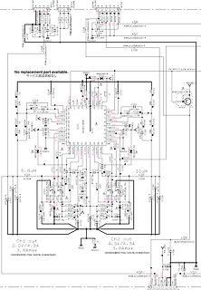
 Bild
Bild
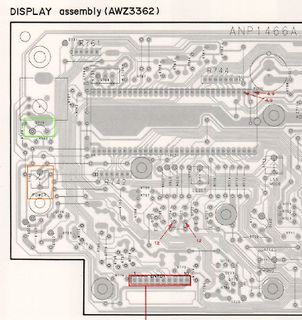
 Bild
Bild