-
Datei
uart.c
(__AVR_ATmega168PB__) || \ defined(__AVR_ATmega328__) || defined(__AVR_ATmega328P__) || \ defined(__AVR_ATmega3250__) || defined(__AVR_ATmega3290__) ||defined(__AVR_ATmega6450__) || defined(__AVR_ATmega6490__) /
in „Wie macht man solche Lichtmodes? Lauflicht, PWM und Co“ · Mikrocontroller und Digitale Elektronik ·
-
 Bild
Bild
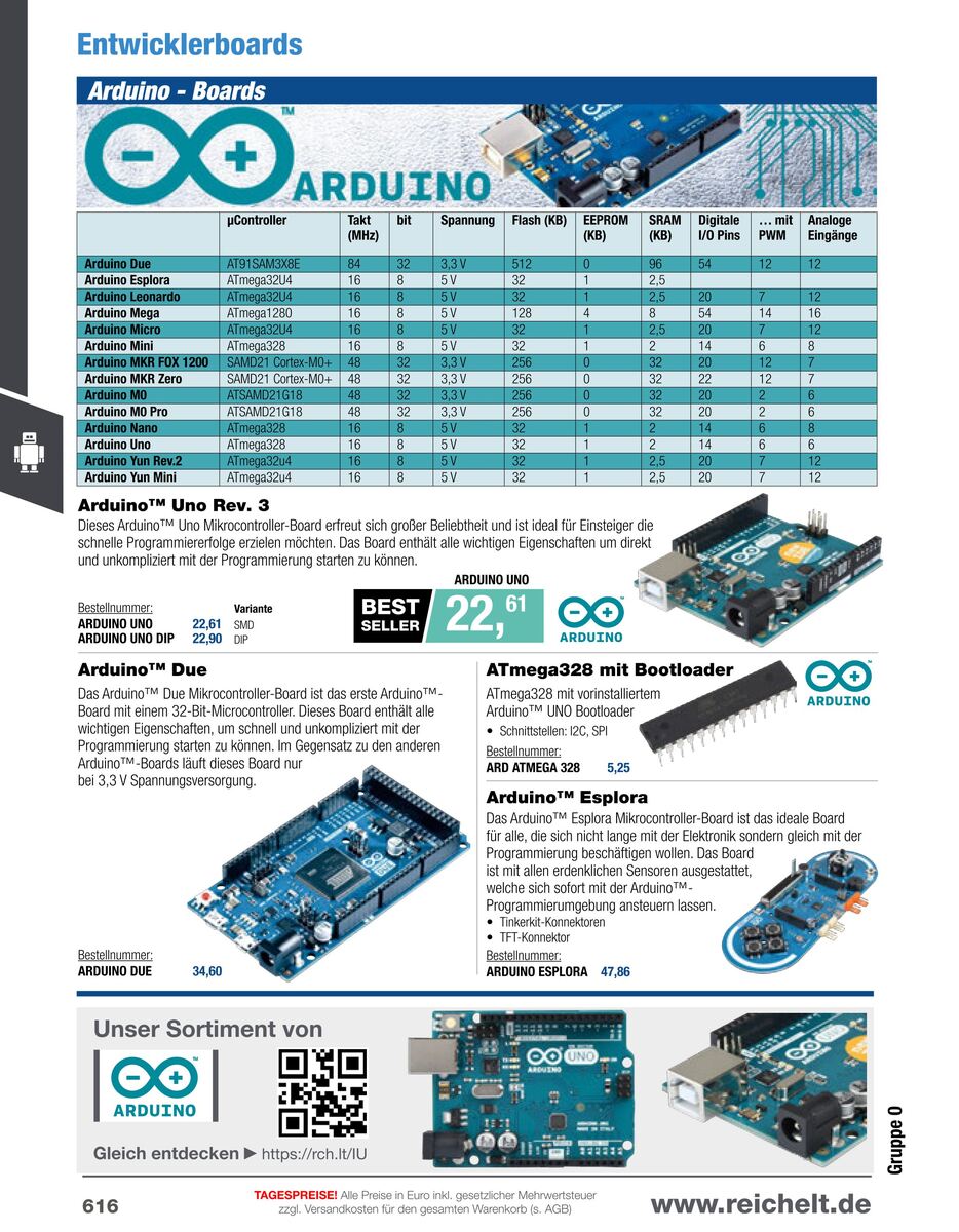
Übersichtstabelle und Fotos verschiedener Arduino-Entwicklerboards
Entwicklerboards Arduino - Boards AT91SAMX3E84 32 3.3V 512 0 96 54 12 Arduino Due Arduino Explora ATmega32A64 16 8 5V 32 1 2,5 12 Arduino Leonardo ATmega328P 16 8 5V 32 1 2,5 20 Arduino Mega ATmega2560 16 8 5V 128 4 84 20 12 Arduino Micro ATmega32A64 16 8 5V 32 1 2,5 20 Arduino Mini ATmega328P 16 8 5V 32 1 2 14 6 8 Arduino Nano SAMD21 Cortex-M0+ 48 32 3.3V 256 0 32 20 12 Arduino Due Uno Rev. 3 ATmega32A64 16 8 5V 32 1 2,5 20 7 12 Arduino Uno Rev. 3 ATmega328 mit Bootloader Arduino Due ATmega328 mit vorinstalliertem Arduino Uno Bootloader Arduino Uno Preis 22,61 BESTELLNUMMER: ARDUINO UNO DIP 22,90
in „Arduinopreise? WTF?“ · Offtopic · · Screenshots
-
PDF
AVR-ASM_Tutorial.pdf
RFM02 auf dem Board aufzulöten. Siehe: • Pollin Funk-AVR-Evaluationsboard • http://www.pollin.de ATmega8-Entwicklungsplatine Eine weitere Möglichkeit ist dieATmega8-Entwicklungsplatine von shop.mikrocontroller.net. Diese enthält eine Fassung für den Controller, einen Spannungswandler, die Beschaltung
in „AVR-Tutorial als PDF“ · Offtopic ·
-
Datei
sd-reader_20090330_mega328.patch
146) @@ -74,16 +74,19 @@ /* defines for customisation of sd/mmc port access */ #if defined(__AVR_ATmega8__) || \ defined(__AVR_ATmega48__) || \ + defined(__AVR_ATmega48P__) || \ defined(__AVR_ATmega88__) || \ + defined(__AVR_ATmega88P__) || \ defined(__AVR_ATmega168__) || \ - defined(__AVR_ATmega328_
-
Datei
MegaBoot.c
__) #define SIGNATURE_BYTES 0x1E9406 #elif defined (__AVR_ATmega128__) #define SIGNATURE_BYTES 0x1E9702 #else #error "no signature definition for MCU available" #endif /* * Defines for the various USART registers */ #if defined(__AVR_ATmega8__) || defined(__AVR_ATmega16
in „mega128 und Fleury-Bootloader“ · Mikrocontroller und Digitale Elektronik ·
-
Datei
0001-Visual-Studio-2015-Files.patch
Include="src\at8515.h" /> + <ClInclude Include="src\at90canbase.h" /> + <ClInclude Include="src\atmega128.h" /> + <ClInclude Include="src\atmega1284abase.h" /> + <ClInclude Include="src\atmega16_32.h" /> + <ClInclude Include="src\atmega2560base.h" /> + <ClInclude Include="src\atmega668base.h" /> + <
in „Simulavr unter Windows mit Visual Studio 2015 kompilieren“ · Mikrocontroller und Digitale Elektronik ·
-
PDF
Crumb128-CAN_V5.0-5.1_infosheet.pdf
Peripherals Crumb128 V5.0 ATmega128 4kB SRAM 4kB EEPROM 128kB Flash - CP2102 USB-UART converter - mini USB B 5pin connector with RS232 - MAX3221 RS232 transceiver - status LED and tiny reset button Crumb128-CAN AT90CAN128 4kB SRAM 4kB EEPROM 128kB Flash - CP2102 USB-UART converter V5.0 - mini USB B 5pin connector - MAX3221 RS232 transceiver with RS232 - ISO 11898-24V standard CAN transceiver - status LED and tiny reset button Crumb128-CAN AT90CAN128
in „CAN Bus Kommunikation AT90CAN128, Crumb128-CAN V5.0 AVR CAN Modul“ · Mikrocontroller und Digitale Elektronik ·
-
Datei
PWM-Programm.asm
Wert einlesen CPI temp,127 ;wenn Wert = 0 dann gerade aus fahren BREQ UP2 ;Sprung auf UP2 CPI temp, 128 ;wenn Wert >= 128 dann nach vorne rechts fahren BRSH UP_RIGHT ;Sprung auf UP_RIGHT CPI temp, 127 ;wenn Wert < 128 dann nach vorne links fahren BRLO UP_LEFT ;Sprung auf UP_LEFT UP2: IN temp, PORTB ;entsprechende
in „Abschlussprojekt“ · Mikrocontroller und Digitale Elektronik ·
-
Datei
Problem_eeprom.txt
#include <mega128.h> #include <stdio.h> #include <delay.h> #include <ctype.h> #define wait delay_ms(100) eeprom unsigned char kennung[6]={'A','-','0','0','0','0'}; void Init(void) { //Register des AVRs initialisieren
in „ATmega128 Problem beim eeprom lesen“ · Mikrocontroller und Digitale Elektronik ·
-
Datei
TCB_A2_perCCL.asm
SLdt 221113 Disclaimer: None. Sue me. Assembler: avrasm2 uC-Forum: "AVR128DB28: TCB0 liefert kein Signal an PA2" https://www.mikrocontroller.net/topic/529706#new TCB im 'Periodic Interrupt Mode' liefert kein Ausgangssignal: erzeugen per CCL AVR® DB Family: AVR128DA28, AVR128DB28, AVR128DB48 megaAVR® 0-series: ATmega4809 ... ... ... ;****************************************************** ; Beispiel: Systemtakt/16000 auf A2: sbi VPORTA_DIR,2 putiw TCB0_CCMP,4000 -1 puti TCB0_CTRLB,0b0
in „Frage zu CCL-Einheit in neueren AVR-Controllern“ · Mikrocontroller und Digitale Elektronik ·
-
Datei
Sinus.c
zurückgesetzt - Clear Timer // gew. Frequenz: 500Hz // 500Hz => 8MHz/500Hz = 16.000 Overflows/Periode // z.B. 128 Bit: 16.000 / 128 Bit = 125 Overflows / Bit } void pwm_init(void) { /* PWM-Output: OC0B */ /* OC0B -> ATmega88 PD5 */ /* OC0A -> ATmega88 PD6 */ TIMSK0 = (1<<OCIE0B); // Output Compare Interrupt 0B
in „Stabilitätsproblem oder Verständnisproblem bei Timer (PWM) ATmega88“ · Mikrocontroller und Digitale Elektronik ·
-
Datei
avr-size.txt
\Alpha Bord>avr-size --mcu=atmega169 -C LCD_functions.elf avr-size: 'LCD_functions.elf': No such file C:\Temp\AVR Programme\Alpha Bord>avr-size --mcu=atmega169 -C LCD_functions.o AVR Memory Usage ---------------- Device: atmega169
in „zu wenig speicher? atmega 169“ · Mikrocontroller und Digitale Elektronik ·
-
Datei
main.c
_1) printf(" / "); #endif /* Print MCU version */ #if (PAL_GENERIC_TYPE == AVR) #if (PAL_TYPE == ATMEGA1281) printf("ATmega1281"); #elif (PAL_TYPE == ATMEGA2561) printf("ATmega2561"); #elif (PAL_TYPE == ATMEGA644P) printf("ATmega644P"); #elif (PAL_TYPE == ATMEGA1284P) printf("ATmega1284P"); #elif (PAL_TYPE
in „performance Testprogramm Atmel MAC“ · HF, Funk und Felder ·
-
Datei
avr-m8_z80.asm
adrl,temp adc adrh,temp2 cpi zl,low(sectbuff+128) brne iplwriteloop cpi zh,high(sectbuff+128) brne iplwriteloop ;Init z80 ldi temp,0x00 mov z_pcl,temp ldi temp,0x20 mov z_pch,temp ldi trace,0 rcall printstr .db 13,"Ok, CPU is live!",13,0,0 main: ldi
in „CP/M auf ATmega88“ · Mikrocontroller und Digitale Elektronik ·
-
PDF
ICprog-AVR.pdf
Tabelle 1 ange- • unterstutzte AVR-Controller gebenen Pinbelegungen, die automatisch erkannt werden. ATmega: ATmega8, ATmega16, ATmega32, ATmega64, AT- Abbildung 2 zeigt die dazugehorige Pinnummerierung der Stiftleiste J2. mega102, ATmega128, ATmega161, ATmega162, ATmega163, ATmega169, ATmega8515, ATme-
in „USB Programmer ICprog-AVR“ · Mikrocontroller und Digitale Elektronik ·
-
PDF
ttester_ger109k.pdf
(Toleranz von 0,1%), um die volle Genauigkeit zu erreichen. Man sollte Präzisions-Sockel für den ATmega Mikrocontroller verwenden um die Austauschbarkeit des Mikrocontrollers sicherzustellen. Es kann ein ATmega8, ATmega168 und ATmega328 Mikrocontrol- ler verwendet werden. Empfohlen werden ATmega168 oder
in „Sammelbestellung Transistortester III - schnelle Runde“ · Markt ·
-
PDF
ttester.pdf
(Toleranz von 0,1%), um die volle Genauigkeit zu erreichen. Man sollte Präzisions-Sockel für den ATmega Mikrocontroller verwenden um die Austauschbarkeit des Mikrocontrollers sicherzustellen. Es kann ein ATmega8, ATmega168 und ATmega328 Mikrocontrol- ler verwendet werden. Empfohlen werden ATmega168 oder
in „Sammelbestellung Transistortester III - schnelle Runde“ · Markt ·
-
Datei
config.inc
--------------------------------- ; ; Hardware and feature configuration ; ; Supported MCUs are: atmega328P atmega168 atmega88 atmega8 ; Z80 emulation currently needs atmega328P, so this is the default. #define atmega328p ; MCU frequency in Hz. #define F_CPU 20000000 ; Set this to 0, if you have a (one
in „CP/M auf ATmega88“ · Mikrocontroller und Digitale Elektronik ·
-
PDF
AVR-ASM-Tutorial_16_05_08_v2.pdf
unbegrenzt Lesezyklen unbegrenzt unbegrenzt unbegrenzt flüchtig nein nein ja Größe beim ATtiny2313 2 KB 128 Byte 128 Byte Größe beim ATmega8 8 KB 512 Byte 1 KB Größe beim ATmega32 32 KB 1 KB 2 KB 12.1.1 Flash-ROM Das Flash-ROM derAVRs dient als Programmspeicher. Über den Programmieradapter werden die kompilierten
in „AVR-ASM-Tutorial: PDF 16.5.08“ · www.mikrocontroller.net ·
-
Datei
hsb255.asm
;============================================== ; HSB -> RGB Umrechnung für ATiny und ATmega ; ; INPUT: ; HSB_H(Sram) byte[0..191°] (Hue) Farbwinkel 0°=rot, 64°=grün, 128°=blau ; HSB_S(Sram) byte[0..255] (Saturation) Sättigung 0=grau, 128=wenig Sättigung, 255=reine Farbe ; HSB_B(Sram) byte
in „HSB LED Steuerung mit Atmega 8 in ASM suche Hilfe“ · Mikrocontroller und Digitale Elektronik ·
-
Datei
dude511.txt
unknown) avrdude: Recv: @ [40] Device code: 0x40 = (unknown) avrdude: Recv: A [41] Device code: 0x41 = ATMEGA103 avrdude: Recv: B [42] Device code: 0x42 = (unknown) avrdude: Recv: C [43] Device code: 0x43 = ATMEGA128 avrdude: Recv: D [44] Device code: 0x44 = (unknown) avrdude: Recv: E [45] Device code: 0x45
in „avrdude - Probleme unter Mac OS X 10.7 (Lion)“ · Mikrocontroller und Digitale Elektronik ·
-
Datei
dude511_mit_arduino_conf.txt
unknown) avrdude: Recv: @ [40] Device code: 0x40 = (unknown) avrdude: Recv: A [41] Device code: 0x41 = ATMEGA103 avrdude: Recv: B [42] Device code: 0x42 = (unknown) avrdude: Recv: C [43] Device code: 0x43 = ATMEGA128 avrdude: Recv: D [44] Device code: 0x44 = (unknown) avrdude: Recv: E [45] Device code: 0x45
in „avrdude - Probleme unter Mac OS X 10.7 (Lion)“ · Mikrocontroller und Digitale Elektronik ·
-
Datei
Programm.c
C */ if( (PROG_UP_DOWN_SWITCHES == 1) & (x == 0) & (p < 15) ) { x=1; p=p+1; NIBBLE1 = 1; NIBBLE2 = 128; VORWAERTS = 1; PORTA = PORTA | 32; /* LED VORWAERTS einschalten */ PORTB = 0; BEEP(); } if ( (PROG_UP_DOWN_SWITCHES == 2) & (x==0) & (p > 0) ) { x=1; p = p - 1; NIBBLE1 = 1; NIBBLE2 = 128; VORWAERTS
in „STK500 (ISP) und ATMEGA8515 Fuses und Timer/Counter“ · Mikrocontroller und Digitale Elektronik ·
-
Datei
t6963c.h
#define DDR(x) (*(&x - 1)) /* address of data direction register of port x */ #if defined(__AVR_ATmega64__) || defined(__AVR_ATmega128__) /* on ATmega64/128 PINF is on port 0x00 and not 0x60 */ #define PIN(x) ( &PORTF==&(x) ? _SFR_IO8(0x00) : (*(&x - 2)) ) #else #define PIN(x) (*(&x - 2)) /* address
in „T6963C an Mega16 - Einige Pixel verirren sich ^^“ · Mikrocontroller und Digitale Elektronik ·
-
Datei
GPSSystem2.bas
+++++++++++++++++++++++++++++++++++++++++++++++++++++ '+ Dieses Programm dient zum Ansteuern eines 128 x 64 Grafik- + '+ displays. Die Anschlüsse sind wie folgt: + '+ + '+ ________________ ________________________ + '+ | portb.0| | | + '+ | portb.1| | ________________ | + '+ | ATMEGA portb.2|------>-
in „KS0108B Displaytech 64128A“ · Mikrocontroller und Digitale Elektronik ·
-
Datei
Keyb.c
#define DDR(x) (*(&x - 1)) /* address of data direction register of port x */ #if defined(__AVR_ATmega64__) || defined(__AVR_ATmega128__) /* on ATmega64/128 PINF is on port 0x00 and not 0x60 */ #define PIN(x) ( &PORTF==&(x) ? _SFR_IO8(0x00) : (*(&x - 2)) ) #else #define PIN(x) (*(&x - 2)) /* address
in „Display Programmierung mit GCC 16x4 Display“ · Mikrocontroller und Digitale Elektronik ·
-
 Bild
Bild
Microchip Studio Debugging Ansicht
C_N1-ATMEGA128P_P40-M1_(32P40U) (Debugging) - Microchip Studio File Edit View Vassix ASF Project Build Debug Tools Window Help Advanced Mode Quick Launch (Ctrl+Q) main.c C_N1-ATMEGA128... P40-M1_(32P40U) Hex Processor
in „welcher Debugger für 8bit Controller (AVR etc.) ?“ · Mikrocontroller und Digitale Elektronik · · Screenshots

-
Datei
virtualInheritanceTest.s
.uleb128 0x2 .uleb128 0x2e .byte 0x1 .uleb128 0x1 .uleb128 0x13 .uleb128 0x3f .uleb128 0xc .uleb128 0x3 .uleb128 0x8 .uleb128 0x3a .uleb128 0xb .uleb128 0x3b .uleb128 0xb .uleb128 0x49 .uleb128 0x13 .uleb128
in „Warning bei avr-g++“ · Mikrocontroller und Digitale Elektronik ·
-
PDF
avr-libc-user-manual.pdf
avr5 atmega64 AVR ATmega64 avr5 atmega128 AVR ATmega128 avr5 at94k AVR AT94K • -morder1 • -morder2 Change the order of register assignment. The default is r24, r25, r18, r19, r20, r21, r22, r23, r30, r31, r26,
in „C Tutorial gesucht“ · Mikrocontroller und Digitale Elektronik ·
-
Datei
help.c
// Timer0 gesteuerter AD-Wandler mit anschl. Berechnungen // // Atmega16 16MHz Takt // AD-Wandlerkanal ADC0, Bereich 0-5V, 8-bit // Ausgabe binär am PortC (für R/2R Netzwerk) // // Timer0 soll jedesmal bei Overflow (jede 128us) den AD-Wandler für eine Einzelwandlung zünden
in „Timer0 gesteuerter AD-Wandler“ · Mikrocontroller und Digitale Elektronik ·
-
Datei
makefile.txt
the assembler code only # # To rebuild project do "make clean" then "make all". # # MCU name MCU = atmega128 # Output format. (can be srec, ihex, binary) FORMAT = ihex # Target file name (without extension). TARGET = main # List C source files here. (C dependencies are automatically generated.) SRC = $
in „makeFile Problem“ · Mikrocontroller und Digitale Elektronik ·
-
PDF
man_gcc.pdf
", "at90usb646", "at90usb647", "at94k", "m3000". "avr51" "Enhanced" devices with 128@tie{}KiB of program memory. mcu@tie{}= "atmega128", "atmega128a", "atmega128rfa1", "atmega128rfr2", "atmega1280", "atmega1281", "atmega1284", "atmega1284p", "atmega1284rfr2", "at90can128", "at90usb1286", "at90usb1287". "avr6" "Enhanced" devices with 3-byte PC, i.e. with more than 128@tie{}KiB of program memory. mcu@tie{}= "atmega256rfr2", "atmega2560", "atmega2561", "atmega2564rfr2". "avrxmega2" "XMEGA" devices with more than 8@tie{}KiB and up to 64@tie{}KiB of program memory. mcu
in „avr-g++: external linkage von const/PROGMEM Symbol.“ · Mikrocontroller und Digitale Elektronik ·
-
Datei
adc_smalldemo.c
und gibt diese auf der seriellen Schnittstelle wieder aus. Genutzte Referenzspannung intern. MCU: ATmega8 / ATmega48 / ATmega88 / ATmega168 / ATmega328 Clock: intern RC oder extern Quarz Compiler: AVR-GCC 4.8.1 IDE: RSIDE Hardware: ADC1 hat einen vorgeschalteten Spannungsteiler 1M zu 220k (er- moeglicht
in „Fragen zu meinem Batterietester“ · Mikrocontroller und Digitale Elektronik ·
-
PDF
nRF24L01_.pdf
2.4GHz-HowTo von der Beschreibung abweichend sind die folgenden Verbindungen: • nRF24L01+ CE → Arduino D8 (ATMega8 PB0) • nRF24L01+ CSN → Arduino D4 (ATMega8 PD4) • nRF24L01+ IRQ → Arduino D3 (ATMega8 PD3) Gaaaanz wichtig der 100µF Kondensator nahe bei der 3,3V Versorgung für den nRF24L01+ nicht vergessen. Die
in „Repeating und Routing Netzwerk mit Arduino und nRF24L01+“ · Projekte & Code ·
-
PDF
ATMega164_324_644_1284pa.pdf
32 K 1 K 2 K ATmega644A 64 K 2 K 4 K bytes ATmega644PA 64 K 2 K 4 K ATmega1284 128 K 4 K 16 K ATmega1284P 128 K 4 K 16 K 2.3 Pin Descriptions 2.3.1 VCC Digital supply voltage. 2.3.2 GND Ground. 2.3.3 Port A (PA7:PA0)
in „Hilfe bei AD-Wandler!“ · Mikrocontroller und Digitale Elektronik ·
-
Datei
ssd1305-oled-neu.bas
16 , 32 , 0 , 0, Data 0 , 0 , 65 , 65 , 127 , 0 , 0 , 0, Data 0 , 4 , 2 , 1 , 2 , 4 , 0 , 0, Data 128 , 128 , 128 , 128 , 128 , 128 , 128 , 128, Data 0 , 0 , 3 , 7 , 0 , 0 , 0 , 0, Data 0 , 32 , 84 , 84 , 84 , 120 , 0 , 0, Data 0 , 127 , 68 , 68 , 68 , 56 , 0 , 0, Data 0 , 56 , 68 , 68 , 68 , 40 , 0
in „OLED Display mit ssd1305 Chip“ · Mikrocontroller und Digitale Elektronik ·
-
Datei
test.txt
to be called before setup() or some functions won't // work there sei(); 1c2: 78 94 sei // on the ATmega168, timer 0 is also used for fast hardware pwm // (using phase-correct PWM would mean that timer 0 overflowed half as often // resulting in different millis() behavior on the ATmega8 and ATmega168)
in „Arduino Compiler Speicherverwaltung“ · Mikrocontroller und Digitale Elektronik ·
-
Datei
2bascom_listings.txt
$regfile = "m8def.dat" 'ATmega8-Deklarationen $crystal = 3686400 'Quarz: 3,6864 MHz $baud = 38400 'Baudrate zum PC: 38400 Baud ' On Adc Onadc 'ADC-Interrupt-Routine festlegen ' Dim Curch As Byte 'Fuer den momentanen A/D-Kanal Dim
in „AD Wandlung mit 10bit über RS232“ · Mikrocontroller und Digitale Elektronik ·
-
PDF
AVR-ASM-Tutorial_16_05_08_v1.pdf
Programme\Atmel\AVR Tools\AvrAssembler\Appnotes\. Einige Include-Dateien heißen AT90s2313: 2313def.inc ATmega8: m8def.inc ATmega16: m16def.inc ATmega32: m32def.inc ATTiny12: tn12def.inc ATTiny2313: tn2313def.inc Um sicher zu gehen, dass man die richtige Include-Datei hat, kann man diese mit einem Texteditor
in „AVR-ASM-Tutorial: PDF 16.5.08“ · www.mikrocontroller.net ·
-
Datei
Arduino_Console.txt
ffunction-sections -fdata-sections -fno-threadsafe-statics -Wno-error=narrowing -MMD -flto -mmcu=atmega328p -DF_CPU=16000000L -DARDUINO=10808 -DARDUINO_AVR_UNO -DARDUINO_ARCH_AVR "-IC:\\Arduino\\hardware\\arduino\\avr\\cores\\arduino" "-IC:\\Arduino\\hardware\\arduino\\avr\\variants\\standard" "C:\\Users
in „Arduino Uno Bootloader verwenden“ · Mikrocontroller und Digitale Elektronik ·
-
Datei
TMC222_AVR.c
library for using a TMC222 together with AVR processors that have a hardware TWI interface (e.g. ATmega8, ATmega48, ATmega88, ATmega168, ATmega16, ATmega32, ATmega64, ATmega128, AT90CAN128 and many more). It implements and interrupt driven TWI master communication over the TWI of the AVR MCU and utilizes
in „Ansteuerung TMC222“ · Mikrocontroller und Digitale Elektronik ·
-
Datei
TMC222_AVR.c
library for using a TMC222 together with AVR processors that have a hardware TWI interface (e.g. ATmega8, ATmega48, ATmega88, ATmega168, ATmega16, ATmega32, ATmega64, ATmega128, AT90CAN128 and many more). It implements and interrupt driven TWI master communication over the TWI of the AVR MCU and utilizes
in „ELV USB-I2C & Schrittmotorsteuerung iSMT“ · Mikrocontroller und Digitale Elektronik ·
-
Datei
lcd.h
Hardware: any AVR device, memory mapped mode only for AVR with memory mapped interface (AT90S8515/ATmega8515/ATmega128) ***************************************************************************/ /** @mainpage Collection of libraries for AVR-GCC @author Peter Fleury pfleury@gmx.ch http://tinyurl.com/
in „Probleme mit LCD-Display und SPI Übertragung“ · Mikrocontroller und Digitale Elektronik ·
-
Datei
lcd.h
Hardware: any AVR device, memory mapped mode only for AVR with memory mapped interface (AT90S8515/ATmega8515/ATmega128) ***************************************************************************/ /** @mainpage Collection of libraries for AVR-GCC @author Peter Fleury pfleury@gmx.ch http://tinyurl.com/
in „LCD-Display Problem“ · Mikrocontroller und Digitale Elektronik ·
-
Datei
lcd.h
Hardware: any AVR device, memory mapped mode only for AVR with memory mapped interface (AT90S8515/ATmega8515/ATmega128) ***************************************************************************/ /** @mainpage Collection of libraries for AVR-GCC @author Peter Fleury pfleury@gmx.ch http://tinyurl.com/
in „Initialisierung 204b LCD mit ST7066U“ · Mikrocontroller und Digitale Elektronik ·
-
Datei
regelung.c
// Timer0 gesteuerter AD-Wandler mit anschl. Berechnungen // // Atmega16 16MHz Takt // AD-Wandlerkanal ADC0, Bereich 0-5V, 8-bit // Ausgabe binär am PortC (für R/2R Netzwerk) // // Timer0 soll jedesmal bei Overflow (jede 128us) den AD-Wandler für eine Einzelwandlung zünden
in „Timer0 gesteuerter AD-Wandler“ · Mikrocontroller und Digitale Elektronik ·
-
Datei
regelung.c
// Timer0 gesteuerter AD-Wandler mit anschl. Berechnungen // // Atmega16 16MHz Takt // AD-Wandlerkanal ADC0, Bereich 0-5V, 8-bit // Ausgabe binär am PortC (für R/2R Netzwerk) // // Timer0 soll jedesmal bei Overflow (jede 128us) den AD-Wandler für eine Einzelwandlung zünden
in „Timer0 gesteuerter AD-Wandler“ · Mikrocontroller und Digitale Elektronik ·
-
Datei
M8_Test_1.c
/*ATmega8 Lauflicht auf PORTD (PORTB von ATmega8 hat nur 6 I/O Pins auf STK500 !) Frequenz über Poti an PC0 regelbar Programme über Taster an PB0 durchschaltbar Taster mit Routine von P. Dannegger entprellt
in „mega8 Tastenentprellung“ · Mikrocontroller und Digitale Elektronik ·
-
Datei
RTTTL8.bas
Auswertungen verwendet werden 'Timer2 im CTC-Modus 'funktioniert mit kleinen Änderungen auch auf Atmega16/32/644 usw. 'funktioniert mit kleinen Änderungen auch auf ATINY45 '------------------------------------------------------------------------------------- $regfile = "m8def.dat" 'ATmega8-Deklarationen
in „RTTTL-Klingeltoninterpreter für Atmega8 in BASCOM“ · Projekte & Code ·
-
Datei
RTTTL8_2.bas
Auswertungen verwendet werden 'Timer2 im CTC-Modus 'funktioniert mit kleinen Änderungen auch auf Atmega16/32/644 usw. 'funktioniert mit kleinen Änderungen auch auf ATINY45 '------------------------------------------------------------------------------------- $regfile = "m8def.dat" 'ATmega8-Deklarationen
in „RTTTL-Klingeltoninterpreter für Atmega8 in BASCOM“ · Projekte & Code ·