-
Datei
iotnx61.h
/* $Id: iotnx61.h,v 1.6 2007/12/12 14:00:49 arcanum Exp $ */ /* avr/iotnx61.h - definitions for ATtiny261, ATtiny461 and ATtiny861 */ /* This file should only be included from <avr/io.h>, never directly. */ #ifndef _AVR_IO_H_ # error "Include <avr/io.h> instead of this file." #endif #ifndef _AVR_IOXXX_H
in „Fehler in ATtiny461 Definitions-Header“ · Mikrocontroller und Digitale Elektronik ·
-
Datei
tn461def.inc
" ;* Title : Register/Bit Definitions for the ATtiny461 ;* Date : 2007-02-28 ;* Version : 2.24 ;* Support E-mail : avr@atmel.com ;* Target MCU : ATtiny461 ;* ;* DESCRIPTION ;* When including this file in the assembly program file, all I/O register ;*
in „tn461def.inc : woher, schnell und einfach“ · Mikrocontroller und Digitale Elektronik ·
-
PDF
Arduino_Interrupts_by_Nick_Gammon.pdf
Sat 12 Oct 2013 12:50 AM (UTC) Amended on Sat 12 Oct 2013 05:09 AM (UTC) by Nick Gammon Message ATtiny85 sleep mode and wake on pin change The sketch below illustrates putting the ATtiny85 to sleep, and then waking on a pin-change interrupt on D4 (pin 3 on the chip). The pin is put into input-pullup
in „Verständnis AVR Interrupts“ · Mikrocontroller und Digitale Elektronik ·
-
Datei
LCD_2313_M50530.bas
Aus Einem Siemenstelefon Optiset Memory E Samsung 2138a Mit M50530 Controller / Ansteuerung Mit Attiny2313 Und Bascomdemo Version 1.11.8.3 Die 2 Leds Sind Nur Zur Funktionskontrolle Während Der Erschaffung dieses Quick-und-Dirty-Codes nötig und können entfallen. Lcd - > Description -----------------
in „Problem bei 8x24 Zeichen LCD an Atmega 16“ · Mikrocontroller und Digitale Elektronik ·
-
Datei
LCD_2313_M50530.bas
Aus Einem Siemenstelefon Optiset Memory E Samsung 2138a Mit M50530 Controller / Ansteuerung Mit Attiny2313 Und Bascomdemo Version 1.11.8.3 Die 2 Leds Sind Nur Zur Funktionskontrolle Während Der Erschaffung dieses Quick-und-Dirty-Codes nötig und können entfallen. Lcd - > Description -----------------
in „LCD Display 8x24 mit M50530“ · Mikrocontroller und Digitale Elektronik ·
-
Datei
AVR.html
color:#0000ff; } p.hcp22 { font-size:8pt; text-align:center; font-family:Tahoma, sans-serif; } span.hcp23 { font-family:Webdings, serif; } p.hcp24 { font-size:8pt; font-family:Webdings, serif; } span.hcp25 { font-weight:normal; } p.hcp26 { font-size:8pt; font-family:'Courier New' , monospace; font-weight
in „Billige Alternative zu AVR STK 500 oder Wie brenne ich günstig mein Programm auf den Mikrochip?“ · Mikrocontroller und Digitale Elektronik ·
-
PDF
GCC_Tut_Test.pdf
. . . . . . . . . . . . . . . . 81. . . 1.23.2 Zus tzliche Funktionen im Make▯le . . . . . . . . . . . . . . . . . . . . . . . . . . . . . . . . . 84. . . . . . 1.23.3 Externe Referenzspannung des internen Analog-Digital-Wandlers . . . . . . .
-
Datei
RFM02-V9.asm
;RFM02-V9.asm ;Stand: 10.01.2010 ;Senderoutine für RFM02 ;Hardware: ATTiny2313 und RFM02 ;Autor: Andreas Montnacher ;Fusebits: Takt 8 MHz intern, kein Taktvorteiler ;Assembler: GAVRASM, http://www.avr-asm-tutorial.net/avr_de/index.html .DEVICE ATTiny2313 ;PortB .equ SDI=5
in „Beispielprogramm für RFM12 433MHz Funk-Module“ · Projekte & Code ·
-
Datei
tn13servo1.asm
/* Servoimpulsgenerator mit zwei Tastern und zwei Servopositionen mit ATTiny13 Beispielprogramm für Rolf Hegewald zum leichteren Einstieg in die AVR-ASM-Welt 01/2012 www.hanneslux.de Mit den Tastern kann (gemäß einem RS-Flipflop) zwischen zwei Zuständen umgeschaltet werden.
in „Taster-Entprellung am Tiny13 in Assembler“ · Mikrocontroller und Digitale Elektronik ·
-
Datei
servobremse01.asm
/* Servo-Bremse mit ATTiny13 Dient zum Verlangsamen von Servobewegungen und zum Justieren von Neutralpunkt und Drehwinkel. Anschlussbewegung ATTiny13: Pin 1: PB5, Reset Pin 2: PB3, ADC 3 Neutralpunkt Pin 3: PB4, ADC 2 Gain Pin
in „Ich verstehe den Timer0 beim ATtiny 13 nicht.“ · Mikrocontroller und Digitale Elektronik ·
-
 Bild
Bild
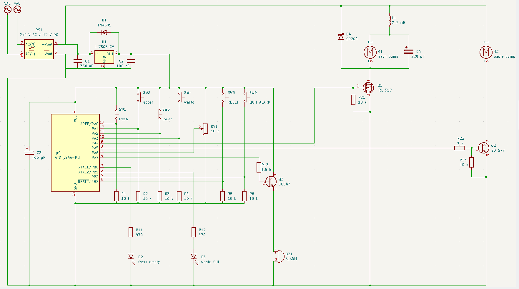
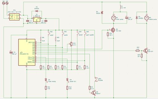
Schaltplan einer Pumpensteuerung mit Mikrocontroller
CV C1 330 uF C2 100 nF M1 fresh pump M2 waste pump D4 SR204 Q1 IRL 510 R21 10 k R22 1 k Q2 BC 677 R23 10 k uC1 Attiny84A-PU RESET PB3 PB2 XTAL2/PB1 XTAL1/PB0 PA7 PA6 PA5 PA4 PA3 PA2 AREF/PA0 VCC SW1 upper SW2 lower SW3 waste SW4 fresh SW5 QUIT ALARM SW6 RESET RV1 10 k R1 10 k R2 10 k R3 10 k R4 10 k
in „DAC-Pumpensteuerung: 5V PWM --> 12 V analog“ · Analoge Elektronik und Schaltungstechnik · · Schaltpläne
-
 Bild
Bild
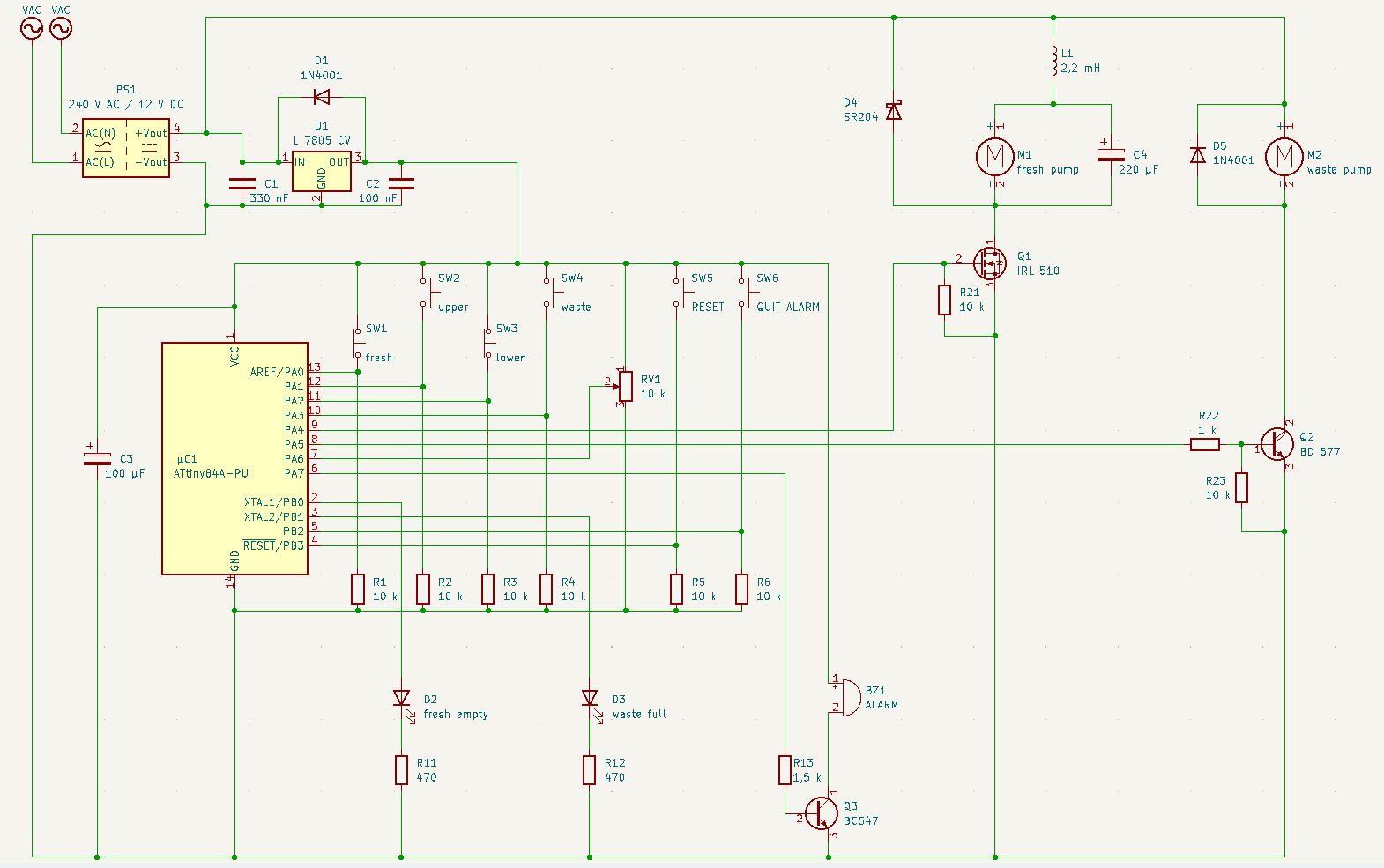
Schaltplan einer Pumpensteuerung mit ATtiny84A
10 k, SW1 upper, SW2 fresh, SW3 lower, SW4 waste, SW5 RESET, SW6 QUIT ALARM, R22 1 k, Q2 BD 677, R23 10 k, RV1 10 k, uC1 ATtiny84A-PU, C3 100 uF, R1 10 k, R2 10 k, R3 10 k, R4 10 k, R5 10 k, R6 10 k, D2 fresh empty, D3 waste full, R11 470, R12 470, R13 1.5 k, Q3 BC547, BZ1 ALARM
in „DAC-Pumpensteuerung: 5V PWM --> 12 V analog“ · Analoge Elektronik und Schaltungstechnik · · Schaltpläne
-
PDF
AVR042_Hardware_Design_Considerations_doc2521.pdf
target application board so that the ISP connectors can be accessed easily. Note: 1. Except the ATtiny10, ATtiny11 and ATtiny28. On most devices the ISP interface is located on the same pins as the SPI interface. However, there are exceptions from this rule, e.g. the ATmega103 and the ATmega128 do not
in „Atmega 8A PU“ · Mikrocontroller und Digitale Elektronik ·
-
Datei
Synth.asm
.nolist .include "tn2313def.inc" ; Define device ATtiny2313 .list ; ***Konstanten*** .equ F_CPU = 10000000 .equ F_ICR = 256 .equ PWM = F_CPU/F_ICR .equ BAUD = 31250 .equ BRC = (F_CPU/16/BAUD)-1 ; ***Defs*** .def rsreg = r15 .def rmp = r16 .def rbuf2 = r17 .def rudr = r18 .def rudr2 = r19 .def rudr3 = r20 .def rdaten = r21 .def rpkl = r22 .def rpkh = r23 .def rbuf = r24 .def rflag = r25 .def rZero = r0 .def rp1l = r3 .def rp1h = r4 .def rp2l = r5 .def rp2h = r6 .def rp3l = r7 .def rp3h = r8 .def rp4l = r9 .def rp4h = r10 ; ***SRAM*** .dseg .org SRAM_START
in „Attiny2313 Timer16 Bit, Normal Mode, unsauber“ · Mikrocontroller und Digitale Elektronik ·
-
PDF
Briefkasten.pdf
3,3 330n R1 8 GND D 10k C G U1 C D1 GND V 5 2 J1 / Vin AREF/PB0 1k LED D PB1 6 R6 N 1 NODEMCU B C1 ATtiny45V-10PU PB2 7 G / GND B 100n 2 2 XTAL1/PB3 XTAL2/PB4 3 1 Q1 1 IRLZ34N RESET/PB5 R2 R4 3 100 N 10k GND G 4 GND GND GND INT0 2 J2 1 Magnet-Schalter GND C C Schaltung mit AtTiny45 Sheet: / D File: Briefkasten.sch D Title: Size: A4 Date: 23.01.2021 Rev: KiCad E.D.A. kicad 5.1.8-5.1.8 Id: 1/1 1 2 3 4 5 6
in „Briefkastenmelder mit ESP-07s und Selbsthaltung mittels Mosfet“ · Mikrocontroller und Digitale Elektronik ·
-
Datei
irsnd.c
Copyright (c) 2010-2015 Frank Meyer - frank(at)fli4l.de * * Supported AVR mikrocontrollers: * * ATtiny87, ATtiny167 * ATtiny45, ATtiny85 * ATtiny44 ATtiny84 * ATmega8, ATmega16, ATmega32 * ATmega162 * ATmega164, ATmega324, ATmega644, ATmega644P, ATmega1284, ATmega1284P * ATmega88, ATmega88P, ATmega168
in „IRMP - Infrared Multi Protocol Decoder“ · Projekte & Code ·
-
PDF
TechnicalReference_IspV2.pdf
Spannungsversorgung über USB • Takterzeugung für falsch konfigurierte Mikrocontroller • Unterstützt alle ATtiny und ATmega AVR Derivate 1.2 Lieferumfang • ISP Programmierer Platine • USB Kabel zum Anschluss an einen Computer • 10 poliges Flachbandkabel • CD mit USB Treibern, Dokumentation und Beispielen 5 1.3
in „unbekanntes Board / Programmer ib-markl“ · Mikrocontroller und Digitale Elektronik ·
-
 Bild
Bild
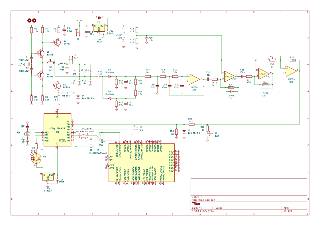
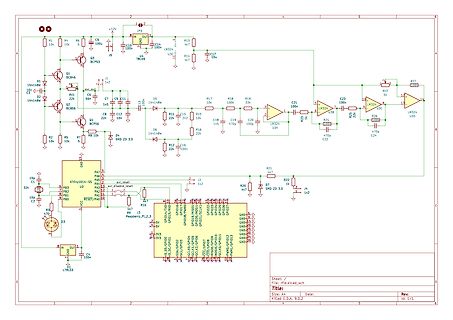
Schaltplan mit Mikrocontroller und Operationsverstärkern
LM324, C17 47, U31, J5, Q1 BC543, R1 1k, C7 100, C8 22n, C11 100, C12 22n, R17 100, R18 33, C21 100, C23 100, R19 1k, U32 LM324, R27 100, R2 10k, R5 10, D1 1N414BW, D2 1N414BW, D4 SMD ZD 3.0, D5 1N414BW, D6 1N414BW, R11 22k, R15 10k, C15 100n, C19 470, C20 150p, R24 100, U33 LM324, C22 470p, C24 470p, U34, R25 1k, R26 100, R22 1k, R20 47, R21 47, PA7, PA6, PA5, PA4, PA3, PA2, PA1, PA0, RESET/PA0, U2 ATtiny1614-SS, PB0 bis PB7, PB1 bis PB7, GND, 3v3, 3v3, GND, GND, GND, GND
in „[VS] Platine RFID - Leser“ · Markt · · Schaltpläne
-
Datei
adc.c
***********************************/ // Einbinden von bestehenden Modulen #include <avr/io.h> // ATtiny45 Register //------------------------------------------------------------------------------ // Makros #define BitSet(Register, Bit) Register = (Register | (0x01 << Bit)) #define BitClr(Register, Bit
in „ADC Problem mit ATtiny45“ · Mikrocontroller und Digitale Elektronik ·
-
Datei
3Koenige_attiny2313.bas
$crystal = 10000000 $regfile = "attiny2313.dat" Dim Servospeed As Integer Dim Negservospeed As Integer Dim I As Integer Dim Centerservo As Integer Dim Leftservo As Integer Dim Rightservo As Integer Config Portb.0 = Output Config Portb.1
in „Problem: Digitalservo mit AVR BOARD steuern“ · Mikrocontroller und Digitale Elektronik ·
-
Datei
LP-Impulse.c
/* Low-Power Impulsgenerator mit ATTiny13, 25, ... An PB0 wird ein kurzer (2 ms) Impuls ausgegeben. Der Impulsabstand wird in 1 s Schritten mit dem WDT per Interrupt erzeugt. Für minimale Stromaufnahme während des aktiven Ausgangsimpulses
in „Micropower Pulsgenerator“ · Analoge Elektronik und Schaltungstechnik ·
-
Datei
irsnd.c
Copyright (c) 2010-2019 Frank Meyer - frank(at)fli4l.de * * Supported AVR mikrocontrollers: * * ATtiny87, ATtiny167 * ATtiny45, ATtiny85 * ATtiny44 ATtiny84 * ATtiny2313 ATtiny4313 * ATmega8, ATmega16, ATmega32 * ATmega162 * ATmega164, ATmega324, ATmega644, ATmega644P, ATmega1284, ATmega1284P * ATmega88
in „IR Fernbedienung mit IRSND“ · Mikrocontroller und Digitale Elektronik ·
-
Datei
t13schalt4_1.asm
/* RC-Schaltmodul mit 4 Schaltausgängen mit ATTiny13 Es wird der Kanalimpuls einer Modellbau-Funkfernsteuerung ausgewertet. Es können 4 Schaltausgänge geschaltet werden. Für jeden Schaltausgang kann durch bedingte Assemblierung die Betriebsart separat
in „Ich verstehe den Timer0 beim ATtiny 13 nicht.“ · Mikrocontroller und Digitale Elektronik ·
-
Datei
USI_TWI_Master.c
/***************************************************************************** * * Modified on 23. Feb. 2018 by Dr. Marko Rocznik in order to work with AtmelStuduio7 * - modifications: including the correct libraries (there were outdated lib names) * - included the correct delay function * - replaces
in „I2C ATtiny167 mit USI“ · Mikrocontroller und Digitale Elektronik ·
-
Datei
main.c
/* SLdt 220912 Disclaimer: none. Sue me. MCP23S17 einfachst: 'Blinken' auf GPIO-A */ #define F_CPU 16000000UL #include "util/delay.h" #include "avr/io.h" // ATmega48PA ATtiny841 #define SPI_DDR DDRB // DDRA #define SPI_PORT PORTB // PORTA #define
in „SPI mit Attiny 841 und MCP23S17“ · Mikrocontroller und Digitale Elektronik ·
-
PDF
Schaltplan.pdf
2 15 SDA 32 31 12V GND VCC VCC VCC SDA 30 29 E 3 INT VBAT 14 VBAT 28 27 T 26 25 O 4 RST GND 13 24 23 E + C1 3.3V 22 21 R 5 12 20 19 3300uf P$1 P$8 18 17 6 11 16 15 P$2 P$7 C2 14 13 LSP4 +VIN -VIN -VOUT +VOUT REMOTE 7 P$3 P$6 10 12 11 GND 100nF 10 9 8 P$4 P$5 9 VCC 8 7 SHUTDOWN 6 5 SCL 4 3 SDA GND GND
in „Raspi Shield - so in Ordnung?“ · Mikrocontroller und Digitale Elektronik ·
-
PDF
Lichtwecker_Rev02_scm.pdf
CLKO/OC1B/ADC2)_PB4 DCIN- DCOUT- (PCINT5/~RESET/ADC0/DW)_PB5 + JP3 4 V 1 GND + C4 GND 2 3 GND GND ATTINY85-20PU 100 µF + 4 V PSK_STECKER4 GND +VIN DCIN+ DCOUT+ +VOUT PROG 1 PROG_MOSI 1 2 PWM PWM E PROG_MISO 3 4 L 5 6 -VIN DCIN- DCOUT- -VOUT PROG_SCK GND 2 k R 1 GND GND I2C H1 1 MOUNT-HOLE3.2 2 H2 MOUNT-HOLE3.2
in „Schaltplan / Layout gegenlesen“ · Mikrocontroller und Digitale Elektronik ·
-
Datei
sinus2313_3.asm
Tabelle ; Ein Sinussignal wird an Port B ausgegeben ; R2R-Netzwerk zur DA-Wandlung ; Testprogramm mit ATTINY2313 .include "tn2313def.inc" .equ F_CPU = 20000000 ; Systemtakt in Hz .equ BAUD = 9600 ; Baudrate ; Berechnungen .equ UBRR_VAL = ((F_CPU+BAUD*8)/(BAUD*16)-1) ; clever runden .equ BAUD_REAL = (F_CPU
in „wieder einmal dds“ · Mikrocontroller und Digitale Elektronik ·
-
Datei
zeitschalt1_ATTTINY2313.bas
the Atmel 90AT2313 microcontroller 'Zeitschaltuhr59 Minuten 59 Sekunden von LEXATRONIC $regfile = "ATTINY2313.dat" 'AT90S2313-Deklarationen $crystal = 4000000 'Quarz: 4 MHz Start: Dim Ftoggle As Bit 'Schnaggelt bei jedem Interrupt On Timer1 Ontimer1 'Interrupt-Routine für Timer1Overflow Config Timer1 =
in „Probleme mit ATTINY2313“ · Mikrocontroller und Digitale Elektronik ·
-
Datei
Bascom_LM7001.txt
$regfile = "Attiny2313.dat" $prog &HFF , &H64 , &HDF , &HFF ' generated. Take care that the chip supports all fuse bytes. $crystal = 1000000 Lm_da Alias Portd.2 Lm_cl Alias Portd.3 Lm_en Alias Portd.4 Dim Nwert As Word
in „Attiny2313 + LM7001 + Bascom - Wer kann helfen?“ · Mikrocontroller und Digitale Elektronik ·
-
Datei
LM7001.bas
$regfile = "Attiny2313.dat" $prog &HFF , &H64 , &HDF , &HFF ' generated. Take care that the chip supports all fuse bytes. $crystal = 1000000 Lm_da Alias Portd.2 Lm_cl Alias Portd.3 Lm_en Alias Portd.4 Dim Nwert As Word
in „Attiny2313 + LM7001 + Bascom - Wer kann helfen?“ · Mikrocontroller und Digitale Elektronik ·
-
Datei
hd44780_i2c.h
fuer Anbindung eines HS44780 kompatiblen Textdisplays ueber einen PCF8574 I2C I/O Expander MCU : ATtiny44 F_CPU : 8 MHz intern Fuses : fuer 8 MHz intern lo 0xe2 hi 0xdf Fuses : fuer ext. Quarz >= 8 MHz lo 0xde hi 0xdf Benoetigt i2c_sw.c Pinbelegung I2C --------------- PB0 = SDA PB1 = SCL 23.10.2018 R
in „(sehr) kleines "FrameWork" für ATtiny44“ · Projekte & Code ·
-
Datei
main.c
/* * LED_Fading_ATtiny13A.c * * Created: 22.11.2016 23:25:19 * Author : e0909 * http://www.mikrocontroller.net/topic/241330 */ #include <avr/io.h> #include <avr/interrupt.h> #include <avr/power.h> #include <avr/sleep.h>
in „ATtiny13 Ausfall nach kurzer Laufzeit.“ · Mikrocontroller und Digitale Elektronik ·
-
Datei
Hysterese_4.asm
******************************************************************* ;* Hysterese_4.ASM ;* ;* Für ATtiny26 mit internen Kalibrierten RC-Oszilator von 1Mhz ;* ;* Eine Balkenanzeige aus acht LEDs soll acht Schwellwerte anzeigen. ;* Oberster Schwellwert ueberschritten bedeutet alle LEDs an. ;* Unterster
in „ATtiny26 Balkenanzeige ( Hysterese ) mit acht Schaltschwellen (ASM)“ · Projekte & Code ·
-
Datei
dds.txt
Tabelle ; Ein Sinussignal wird an Port B ausgegeben ; R2R-Netzwerk zur DA-Wandlung ; Testprogramm mit ATTINY2313 .include "tn2313def.inc" .equ F_CPU = 20000000 ; Systemtakt in Hz .equ BAUD = 9600 ; Baudrate ; Berechnungen .equ UBRR_VAL = ((F_CPU+BAUD*8)/(BAUD*16)-1) ; clever runden .equ BAUD_REAL = (F_CPU
in „Einfaches Labornetzteil? R2R + großer Transistor“ · Mikrocontroller und Digitale Elektronik ·
-
Datei
led.c
********* * * LED strip Steuerung mit IR * Andreas Brietzke, Nagareyama-shi, J * * * Chip type : ATtiny2313 * Clock frequency : 8 MHz * lfuse 64 = 0110 0000 -> a4 = 1010 0100 * hfuse df = 1101 1111 -> d9 = 1101 1001 * avrdude -p t2313 -c usbasp -B 10 -U lfuse:w:0xa4:m -U hfuse:w:0xd9:m * * led.c * *
in „ATtiny2313, gcc. unerklärliches Verhalten“ · Mikrocontroller und Digitale Elektronik ·
-
Datei
VU-Meter.c
/* * VU Meter für ATTiny 25 (45/85) für 10 oder 12 LEDs (z.B. 9 grün, 2 gelb, 1 rot) * 15.3.17 * Anregung von https://www.mikrocontroller.net/topic/419372 - dort ist die HW mit einem Tiny13 beschrieben * * Taktfrequenz 8MHz
in „ATTiny25: unklare Interaktion PROGMEM <-> ADC“ · Mikrocontroller und Digitale Elektronik ·
-
Datei
test3.c
/********************************************* This program was produced by the CodeWizardAVR V1.23.8c Professional Automatic Program Generator © Copyright 1998-2003 HP InfoTech s.r.l. http://www.hpinfotech.ro e-mail:office@hpinfotech.ro Project : Version : Date : 19.03.2005 Author : Company : Comments: Chip type : ATtiny26L Clock frequency : 1,000000 MHz Memory model : Tiny External SRAM size : 0 Data Stack size : 32 *********************************************/ #include <tiny26.h> // Declare your global variables
in „CodeVision Einsteiger“ · Mikrocontroller und Digitale Elektronik ·
-
Datei
reichelt.htm
Atmel AVR-RISC-Controller</td> <td><input type="text" name="Input_Unknown[19]" value="ATTINY 2313 DIP" class="artnr"/></td> <td><input type="text" id="item[19]" name="Anzahl_Unknown[19]" maxlength="5" class="menge" value="1"/></td> </tr> <!-- Artikel ENDE --> <!-- Artikel START
-
Datei
device2007.txt
12.7V, MSM27512AS,P27, MSM271000,P27, ____EPROM-RICOH 27C64-21V, 27C256-12.7V, ____EPROM-SAMSUNG KM23C4100,P27, ____EPROM-SEEQ DQ2764-21V,P27, DQ27128-21V, DQ27C256-12.7V, ____EPROM-SGS_THOMSON M27128A-12.7V, M27256,P27, M27CC512,P27, M27C1000,P27, M27C1001,P27, M27C2001,P27, M27C4001,P27, ____EPROM-SIGNETICS
in „24C04 beschreiben und auslesen“ · Mikrocontroller und Digitale Elektronik ·
-
Datei
VU-Meter.c
/* * VU Meter für ATTiny25 (45/85) für 12 LEDs (z.B. 9 grün, 2 gelb, 1 rot) * 15.3.17, HildeK * Anregung von https://www.mikrocontroller.net/topic/419372 - dort ist die HW mit einem Tiny13 beschrieben * * Taktfrequenz 8MHz
in „VU-Meter mit Attiny13a statt LM3916“ · Projekte & Code ·
-
Datei
lcd.c
0x7f, 0x14, 0x7f, 0x14, // # 0x00, 0x24, 0x2a, 0x7f, 0x2a, 0x12, // $ 0x00, 0x62, 0x64, 0x08, 0x13, 0x23, // % 0x00, 0x36, 0x49, 0x55, 0x22, 0x50, // & 0x00, 0x00, 0x05, 0x03, 0x00, 0x00, // ' 0x00, 0x00, 0x1c, 0x22, 0x41, 0x00, // ( 0x00, 0x00, 0x41, 0x22, 0x1c, 0x00, // ) 0x00, 0x14, 0x08, 0x3E, 0x08,
in „RS485 von ms - immer noch Einschaltprobleme“ · Mikrocontroller und Digitale Elektronik ·
-
Datei
Treppenlicht.ino
endif //Variablendeklaration int Melder_unten = 22; // Input Bewegungsmelder unten int Melder_oben = 23; // Input Bewegungsmelder oben int Nanopixel = 6; // Output für NanoPixel LEDs int VZ = 15; // Verzögung Ansteuerung der Stufen int Dauer = 30000; // Leuchtdauer wenn alle Stufen angesteuert sind int
in „Dynamischer Variablenname in Scheife hochzählen“ · Mikrocontroller und Digitale Elektronik ·
-
Datei
Treppenlicht.ino
endif //Variablendeklaration int Melder_unten = 22; // Input Bewegungsmelder unten int Melder_oben = 23; // Input Bewegungsmelder oben int Nanopixel = 6; // Output für NanoPixel LEDs int VZ = 15; // Verzögung Ansteuerung der Stufen int Dauer = 30000; // Leuchtdauer wenn alle Stufen angesteuert sind int
in „Dynamischer Variablenname in Scheife hochzählen“ · Mikrocontroller und Digitale Elektronik ·
-
Datei
LED-Dimmen_2.asm
*********************************************************** ;* Programm LED-Dimmen.ASM ;* ;* Für ATtiny13 mit internen Takt von 1,2 MHz ;* ;* ;* Ein PWM-Ausgang kann ueber einen Taster in vier Schritten ;* im Tastgrad verändert werden ;* oder ;* auch von 255 bis 1 gedimmt werden. ;* ;* ;* PWM-Signal
in „Wie generiere ich eine Pwm mit fester Frequenz aber variablem Tastverhältnis“ · Mikrocontroller und Digitale Elektronik ·
-
Datei
basic1.asm
************************************************************ .include "tn2313def.inc" ;Prozessor ATTINY2313 ; ATtiny2313 Display 0802 4 bit Mode ; +--+-+--+ 2 Zeilen zu je 8 Stellen ; !RESET | |_| | VCC Memoryadr.: Zeile1: 00 und Zeile2: 40h ; (RX)PD0 | | PB7(SCK) ---W_CLK. ; (TX)PD1 | | PB6(MISO)---
in „Dynamisierung Encoder speziell für DDS“ · Mikrocontroller und Digitale Elektronik ·
-
PDF
Schaltplan.pdf
GND C4 TxD<-PC 5 6 C7 1µF 11 T1 14 1µF 7 8 100n 10 T2 7 9 10 12 R1 13 9 R2 8 10-PINSTECKER 2 D1 R1 ATTINY2313 47k MAX232E green V2 R2 11 PD6 C RESET 1 1N4148 C6 +5V C24 C R15 100n 1 X1 330R H1 12 PB0 V PD0/RxD 2 100n red 10k 2 +5V R3 3 13 PB1 PD1/TxD 3 X3 C 4 390R H2 +5V 1 +5V R14 C23 C 5 14 PB2 OC0A PD2
in „ATtiny2313 ungewollter Reset?“ · Mikrocontroller und Digitale Elektronik ·
-
Datei
tn1634def.inc
" ;* Title : Register/Bit Definitions for the ATtiny1634 ;* Date : 2011-05-12 ;* Version : 2.35 ;* Support E-mail : avr@atmel.com ;* Target MCU : ATtiny1634 ;* ;* DESCRIPTION ;* When including this file in the assembly program file, all I/O register
in „ATTINY1634 und Assembler“ · Mikrocontroller und Digitale Elektronik ·
-
Datei
august2011_tn1634def.inc
" ;* Title : Register/Bit Definitions for the ATtiny1634 ;* Date : 2011-08-25 ;* Version : 2.35 ;* Support E-mail : avr@atmel.com ;* Target MCU : ATtiny1634 ;* ;* DESCRIPTION ;* When including this file in the assembly program file, all I/O register
in „ATTINY1634 und Assembler“ · Mikrocontroller und Digitale Elektronik ·
-
Datei
DEFEKT_tn1634def.inc
" ;* Title : Register/Bit Definitions for the ATtiny1634 ;* Date : 2011-05-12 ;* Version : 2.35 ;* Support E-mail : avr@atmel.com ;* Target MCU : ATtiny1634 ;* ;* DESCRIPTION ;* When including this file in the assembly program file, all I/O register
in „ATTINY1634 und Assembler“ · Mikrocontroller und Digitale Elektronik ·