-
PDF
AVR_ISP_USER_GUIDE.PDF
that the firmware in the pro- grammer is outdated. The following devices are currently supported: ATtiny12 ATtiny15 ATtiny22 AT90S1200 AT90S2313 AT90S/LS2323 AT90S/LS2343 AT90S/LS2333 AT90S4414 AT90S/LS4433 AT90S/LS4434 AT90S8515 AT90S/LS8535 ATmega161(L) ATmega16(L) ATmega163(L) ATmega32(L) ATmega323
-
Datei
ir.asm
;************************************************ ;RC 5 decoding programm ;device: ATtiny 13 ;autor: Steven Weyrich ;************************************************ .org 0x0000 ;adress for initial programm rjmp RESET .org 0x0002 ;Adress for pin change interrupt rjmp PCINT0 .org 0x0006
in „Pinchange-Interrupt“ · Mikrocontroller und Digitale Elektronik ·
-
Datei
FPWM_Mode7.asm
*********************************************************** ;* Programm FPWM_Mode7.ASM ;* ;* Für ATtiny13 im Auslieferungszustand ( High = $FF ; Low = $6A ) ;* ;* ;* Am PWM-Pinn 6 ( OC0B ) wird eine PWM im Mode 7 ausgegeben, ;* die mittels zweier Potentiometer eingestellt wird. ;* Wobei ein Poti Pinn
in „ATtiny13 Fast PWM-Mode mit OCR0A und extremwerten“ · Mikrocontroller und Digitale Elektronik ·
-
Datei
Synth.asm
.nolist .include "tn2313def.inc" ; Define device ATtiny2313 .list ; ***Konstanten*** .equ F_CPU = 10000000 .equ F_ICR = 256 .equ PWM = F_CPU/F_ICR .equ BAUD = 31250 .equ BRC = (F_CPU/16/BAUD)-1 .equ MAXBUF = 40 ; ***Defs*** .def rsreg = r15 .def rmp = r16
in „Attiny2313 Timer16 Bit, Normal Mode, unsauber“ · Mikrocontroller und Digitale Elektronik ·
-
Datei
device2007.txt
AT90S8515, AT90LS8515, AT90S4434, AT90S8535, AT90LS8535, AT90S4434, AT90LS4434, AT90S2333, AT90S4433, ATTINY11, ATTINY12, ATTINY15L, ATTINY26, ATTINY26L, ATTINY28L, ATTINY28V, ATTINY2313, ATTINY2313V, ATMEGA8, ATMEGA8L, ATMEGA16, ATMEGA16L, ATMEGA32, ATMEGA32L, ATMEGA8515, ATMEGA8515L, ATMEGA8535, ATMEGA8535L
in „24C04 beschreiben und auslesen“ · Mikrocontroller und Digitale Elektronik ·
-
Datei
Sensor1.asm
******************************* ;** ** ;** ** ;** Research Project; ** ;** Sensor with Microchip ATtiny26(L) ** ;** Programmed by Christian Worch ** ;** Last change: 27.03.2006 ** ;** Version: 0.1 ** ;** ** ;** ** ;********************************************************************************* .include "tn26def.inc" ;Processor specific variable definition ;********************************************************************************* ;** Configuration ** ;**********************************************
in „ATTiny26 und ein Problem mit dem EEPROM“ · Mikrocontroller und Digitale Elektronik ·
-
Datei
avr910_2313_v38c.asm
Added support for swapped MISO/MOSI lines. Automatically detected on 'Enter Programming Mode' ;* V3.8b 26.02.06 (Klaus) Matched new Devices to avrdude.conf v5.1 ;* V3.8a 30.12.05 (Klaus) Corrected Devic entry for ATTiny13 ;* V3.8 06.11.05 (Klaus) New Devicecodes (inoffiacal) for Mega48/88/168 and others,
in „Programmer incl. neuem Code für Atmel AN910“ · Projekte & Code ·
-
Datei
dann.lst
1 .file "dann.c" 2 .arch attiny26 3 __SREG__ = 0x3f 4 __SP_H__ = 0x3e 5 __SP_L__ = 0x3d 6 __tmp_reg__ = 0 7 __zero_reg__ = 1 8 .global __do_copy_data 9 .global __do_clear_bss 11 .text 12 .Ltext0: 49 .global display_write 51 display_write
in „Welchen WINAVR nehmen ?“ · Mikrocontroller und Digitale Elektronik ·
-
Datei
TPS_UP.h
/*************************************************************************************** Titel: ATtiny TPS Unterprogramme Author: Christian Hottum File: TPS_UP.h Version: 0.1 Datum: 09.01.2015 Software: AVR-GCC 4.3.3 Target: ATtiny461A DESCRIPTION Variablen und Unterprogramme der TPS ***************
in „AVR TTiny 461 Pullup nicht aktiv?“ · Mikrocontroller und Digitale Elektronik ·
-
Datei
12V_Tiefentladeschutz_19.asm
****************************************************** ;* 12V_Tiefentladeschutz_19.ASM ;* ;* Für ATtiny26 mit internen Kalibrierten RC-Oszilator von 1Mhz ;* ;* Mit LCD im 4-Bit Mode ;* ;* ADC-Takt => Systemtakt/16 = 62,5 Khz => 16µs ;* ;* Timer0-Takt => Systemtakt/1 = 1MHz => 1µs ;* ;* Timer1-Takt =>
in „Wie geht man ein Assemblerprojekt an ?“ · Mikrocontroller und Digitale Elektronik ·
-
Datei
Mardenschreck.asm
on-time elapsed or day ; light threshhold is calculated ; DayLow PB2 shows night (hi) or day (lo) ; ATtiny15 GS 07-2011, ok ; The timing is adapted for 1.6 MHz ; ; This program is free software; you can redistribute it and/or ; modify it under the terms of the GNU General Public License. ; This program
in „Marderschreck Softwareproblem“ · Mikrocontroller und Digitale Elektronik ·
-
Datei
Mardenschreck.asm
on-time elapsed or day ; light threshhold is calculated ; DayLow PB2 shows night (hi) or day (lo) ; ATtiny15 GS 07-2011, ok ; The timing is adapted for 1.6 MHz ; ; This program is free software; you can redistribute it and/or ; modify it under the terms of the GNU General Public License. ; This program
in „Marderschreck Softwareproblem“ · Mikrocontroller und Digitale Elektronik ·
-
Datei
ad-wandler-b1.txt
.device ATtiny26 .nolist .include "tn26def.inc" .list .def temp1 = r16 ; allgemeines temp Register, zur kurzfristigen Verwendung .def temp2 = r17 ; 8 höchstwertigen bits für display .def adlow = r18 ; Ergebnis vom
in „Wert des ADU auf Display ausgeben / ATtiny / Assembler“ · Mikrocontroller und Digitale Elektronik ·
-
 Bild
Bild
Software-Anzeige eines Mikrocontroller-Programmierers
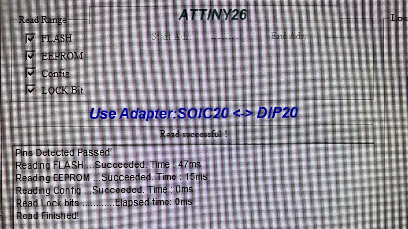
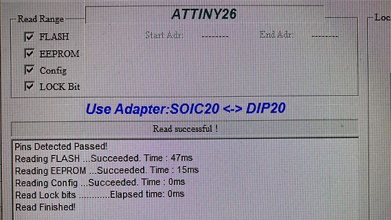
ATTINY26 Read Range FLASH EEPROM Config LOCK Bit Start Adr: ------ End Adr: ------ Use Adapter:SOIC20 <-> DIP20 Read successful ! Pins Detected Passed! Reading FLASH ...Succeeded. Time : 47ms Reading EEPROM
in „ATTINY26L mit TL866 per ISP auslesen“ · Mikrocontroller und Digitale Elektronik · · Fotos
-
Datei
dragon-fuse.txt
jtagmkII_recv(): Got message seqno 0 (command_sequence == 0) avrdude: Recv: . [86] . [01] . [ff] & [26] . [07] . [01] . [ff] & [26] . [07] . [07] . [00] . [a2] . [00] . [01] . [91] . [15] A [41] V [56] R [52] D [44] R [52] A [41] G [47] O [4f] N [4e] . [00] Raw message: 0x86 0x01 0xff 0x26 0x07 0x01 0xff
in „avrdude fuses aus debugwire schreiben“ · Mikrocontroller und Digitale Elektronik ·
-
Datei
tiny26_adc_01.bas
$regfile = "attiny26.dat" $crystal = 1000000 Config Adc = Single , Prescaler = Auto , Dim A As Byte Dim B As Byte Dim C As Word Open "COMB.6:9600,8,N,1,Inverted" For Output As #1 Waitms 500 Print #1 , "HALLO" Do Start
in „tiny26 adc nur 6 bit?“ · Mikrocontroller und Digitale Elektronik ·
-
Datei
tn1634def.inc
" ;* Title : Register/Bit Definitions for the ATtiny1634 ;* Date : 2011-05-12 ;* Version : 2.35 ;* Support E-mail : avr@atmel.com ;* Target MCU : ATtiny1634 ;* ;* DESCRIPTION ;* When including this file in the assembly program file, all I/O register
in „ATTINY1634 und Assembler“ · Mikrocontroller und Digitale Elektronik ·
-
Datei
august2011_tn1634def.inc
" ;* Title : Register/Bit Definitions for the ATtiny1634 ;* Date : 2011-08-25 ;* Version : 2.35 ;* Support E-mail : avr@atmel.com ;* Target MCU : ATtiny1634 ;* ;* DESCRIPTION ;* When including this file in the assembly program file, all I/O register
in „ATTINY1634 und Assembler“ · Mikrocontroller und Digitale Elektronik ·
-
Datei
DEFEKT_tn1634def.inc
" ;* Title : Register/Bit Definitions for the ATtiny1634 ;* Date : 2011-05-12 ;* Version : 2.35 ;* Support E-mail : avr@atmel.com ;* Target MCU : ATtiny1634 ;* ;* DESCRIPTION ;* When including this file in the assembly program file, all I/O register
in „ATTINY1634 und Assembler“ · Mikrocontroller und Digitale Elektronik ·
-
 Bild
Bild
Software-Interface für AVR-Mikrocontroller-Konfiguration
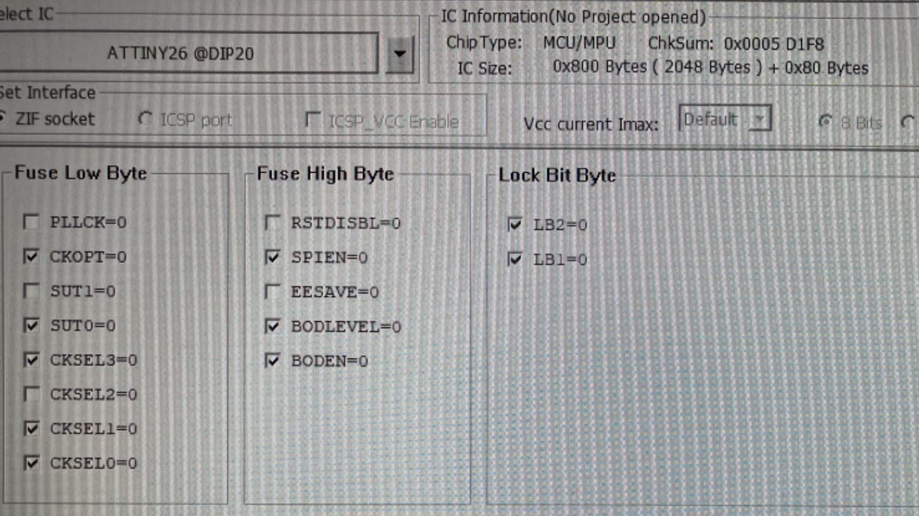
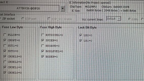
elect IC ATTINY26 @DIP20 IC Information(No Project opened) ChipType MCU/MPU ChkSum: 0x0005 D1F8 IC Size: 0x800 Bytes ( 2048 Bytes ) + 0x80 Bytes Set Interface ZIF socket ICSP port ICSP_VCC Enable Vcc current Imax:
in „ATTINY26L mit TL866 per ISP auslesen“ · Mikrocontroller und Digitale Elektronik · · Fotos
-
Datei
Thermometer.asm
;IDE : AVRStudio V4.09 ;µC : ATtiny15L ;Thermometer mit LED-Segmentanzeige .include "tn15def.inc" ; .def Ziffer = r20 ;Dualzahl-Buffer .def ZBuffer = r16 ;Zeichen-Buffer .def LEDAdresse = r17 ;Multiplexer-Adresse .def temp = r18 ;Temporär-Register
in „kleines Problemchen bei ADC-Messung...“ · Mikrocontroller und Digitale Elektronik ·
-
Datei
sweep_test.asm
************************************************************* ;*Programm Sweep_test.ASM ;* ;*Für ATtiny13 mit internen voreingestellten Takt von ??? Hz ;* ;* ;* Zwei synchrone symetrische Rechtecksignale können über ein Poti in ihrer Frequenz ;* im Bereich von 62,5Hz bis 16kHz verändert werden. ;* ;*
in „ATtiny13 LED-blinken an PB2 und PWM-Mode 7 nicht möglich“ · Mikrocontroller und Digitale Elektronik ·
-
Datei
USI_TWI_Master.c
Supported devices : All device with USI module can be used. * The example is written for the ATmega169, ATtiny26 and ATtiny2313 * * AppNote : AVR310 - Using the USI module as a TWI Master * * Description : This is an implementation of an TWI master using * the USI module as basis. The implementation assumes
in „Attiny 2313A - ROM am Limit? Probleme mit Optimierer“ · Mikrocontroller und Digitale Elektronik ·
-
Datei
USI_TWI_Master.c
Supported devices : All device with USI module can be used. * The example is written for the ATmega169, ATtiny26 and ATtiny2313 * * AppNote : AVR310 - Using the USI module as a TWI Master * * Description : This is an implementation of an TWI master using * the USI module as basis. The implementation assumes
in „Attiny 2313A - ROM am Limit? Probleme mit Optimierer“ · Mikrocontroller und Digitale Elektronik ·
-
PDF
Amadeus.pdf
enjoy fast software updates. No more waiting.... 2.1 Supported Devices µC Additonal Information ATtiny11 High-voltage serial programming ATtiny12 High-voltage serial programming only - Tested ATmega8 xxx ATmega16 Not Tested ATmega32 xxx ATmega64 Tested ATmega128 Not Tested PIC12F629 Not Tested PIC12F675
in „USB-Programmer für eine Reihe von PICs und AVRs“ · Mikrocontroller und Digitale Elektronik ·
-
PDF
firefly1a.pdf
1 A 1 R R2 1.1 1.2 2 + ATTINY45 2 8 5 VCC 6 PB0/PCINT0/AIN0/OC0A/MOSI R5 7 PB1/PCINT1/AIN1/OC0B/INT0/MISO 2 PB2/PCINT2/SCK/ADC1/T0 B R3 3 PB3/PCINT3/CLKI/ADC3 3 1 PB4/PCINT4/ADC2 3 4 PB5/PCINT5/RESET/ADC0/DW GND 1.1 1.2 TINY13-20PU N G 4 R A 4 B 5 5 B A 6 6 26.08.2009 17:03:44 C:\Glühwürmchen\firefly1a.sch (Sheet: 1/1)
in „Glühwürmchen in Rotkohlglas gefangen“ · Projekte & Code ·
-
PDF
speedtron_1.8.pdf
C Output VCC 1 V 7 VCC Input PB5 PB2 1 2 6 1 2 PB3 PB1 2 3 3 5 3 PB4 PB0 SW1 GND GND D Reed G B ATTINY13A B 4 GND GND A A Title Size Number Revision B Date: 26-May-2017 Sheet of File: \\tsclient\I\Alex\Alex.ddb Drawn By: 1 2 3 4 5 6
in „Bosch E-Bike Antrieb Geschwindigkeitssensor“ · Fahrzeugelektronik ·
-
PDF
Stamp_Doku.pdf
Beschreibung Autor neuer Nr. Datum Version Kapitel Zustand 1 12.09.2014 V01.00 Startversion Joe G. OK 2 26.09.2014 V01.01 Z180 Versorgungsspannungen am Joe G. OK Z180-Stamp Modul, (Pin2, Pin3) Versorgungsspannungen am 3 28.09.2014 V01.02 Z180 Z180-Stamp Modul, (Pin2, Pin3) Joe G. OK 4 22.12.2014 V01.03 Inbetriebnahme
in „Z180-Stamp Modul“ · Mikrocontroller und Digitale Elektronik ·
-
Datei
main.c
// Controller: ATTiny26 // Programmbeschreibung: DCF-Modul an PORT PB6 // Erstellungsdatum: 07.07.2006 // Datum der letzten Änderung: 07.07.2006 #include <avr/io.h> #include <stdint.h> #include <avr/interrupt.h> #include
in „Externer Interrupt 0 - ATTiny26“ · Mikrocontroller und Digitale Elektronik ·
-
PDF
isel-interface.pdf
c22 13 IN1 4 a23 c23 U3A VCC N 5 74LS132 U7 C G a24 c24 J1 DIR_X 1 V 8 2 7 a25 c25 R5 R 4 3 A1 +5V a26 c26 2 1 VO1 IDIR_X a27 c27 330R 7 4 C 813 C1 3 k V a28 c28 2 2 7 R 4 A1 a29 c29 RN1 U3B R 4 1 R17 OUT1 74LS132 A2 IN2 VO1 330R VCC a30 c30 VCC +5V CLK_X 4 3 VO2 ICLK_X 7 C1 IIN2 a31 c31 1 2 OUT2 R6 6
in „kleiner Wachhund für CNC-Steuerungen“ · Projekte & Code ·
-
Datei
iotnx61.h
/* $Id: iotnx61.h,v 1.6 2007/12/12 14:00:49 arcanum Exp $ */ /* avr/iotnx61.h - definitions for ATtiny261, ATtiny461 and ATtiny861 */ /* This file should only be included from <avr/io.h>, never directly. */ #ifndef _AVR_IO_H_ # error "Include <avr/io.h> instead of this file." #endif #ifndef _AVR_IOXXX_H
in „Fehler in ATtiny461 Definitions-Header“ · Mikrocontroller und Digitale Elektronik ·
-
 Bild
Bild
Schaltplan mit Raspberry Pi und Verstärkerschaltung
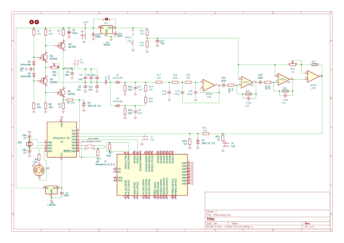
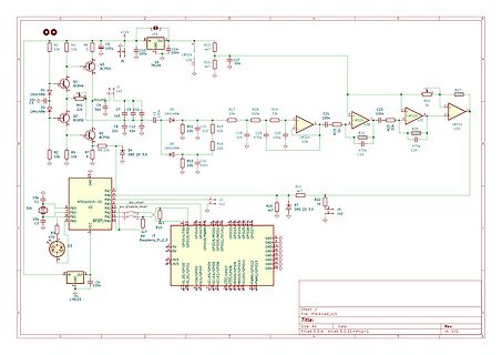
D7, R13, C14, U4, TL09, R17, R18, C21, C23, LM324, U3, R27, R2, R19, R24, C22, C24, R25, R22, R20, R26, R10, R9, R7, R5, R4, R1, R16, R15, R14, R11, R8, R6, R3, C10, C5, C7, C8, C12, C15, C16, C19, C20, C21, C22, C23, C24, Q1, Q2, Q3, D1, D2, D4, D5, D6, U2, ATtiny164-55, P3, P4, P1, P0, RESET/PA0, Raspberry_Pi
in „Bitte nicht nachmachen: PE des DSO abkleben?“ · Analoge Elektronik und Schaltungstechnik · · Schaltpläne
-
Datei
forum.txt
$regfile = "attiny26.dat" Const Quarz = 10000000 '$crystal = intern Do Ampel1_rot Alias Portb.1 Ampel1_gelb Alias Portb.2 Ampel1_gruen Alias Portb.3 Ampel2_gruen Alias Portb.4 Ampel2_gelb Alias Portb.5 Ampel2_rot Alias
in „Hilfe Ampelschaltung mit Bascom ATtiny26“ · Mikrocontroller und Digitale Elektronik ·
-
PDF
firefly1.pdf
1 R1-100R 1.2 1.1 2 1.2 1.1 3 1.2 1.1 4 1.2 1.1 ATTINY45 1.1 1.2 8 5 VCC + R3-330R 6 PB0/PCINT0/AIN0/OC0A/MOSI 7 PB1/PCINT1/AIN1/OC0B/INT0/MISO 2 PB2/PCINT2/SCK/ADC1/T0 1.1 1.2 3 PB3/PCINT3/CLKI/ADC3 1 PB4/PCINT4/ADC2 D 4 PB5/PCINT5/RESET/ADC0/DW N GND G 1 1 1 TINY13-20PU 5B 4B 2B . . . 5 1 1 1 1 1 R2-100R 1.2 1.1 6 3B 6B 1 1.2 1.1 . . 1.2 1.1 1 1 26.08.2009 02:46:04 C:\Programme\EAGLE-5.4.0\projects\examples\singlesided\firefly1.sch (Sheet: 1/1)
in „Glühwürmchen in Rotkohlglas gefangen“ · Projekte & Code ·
-
PDF
firefly1.pdf
1 R1-100R 1.2 1.1 2 1.2 1.1 3 1.2 1.1 ATTINY45 1.1 1.2 8 5 VCC + R3-330R 6 PB0/PCINT0/AIN0/OC0A/MOSI 7 PB1/PCINT1/AIN1/OC0B/INT0/MISO 2 PB2/PCINT2/SCK/ADC1/T0 1.1 1.2 3 PB3/PCINT3/CLKI/ADC3 1 PB4/PCINT4/ADC2 D 4 PB5/PCINT5/RESET/ADC0/DW N GND
in „Glühwürmchen in Rotkohlglas gefangen“ · Projekte & Code ·
-
Datei
LEDBoard_main.c
/* * Led_Board_V1.c * * Created: 29.04.2019 17:26:07 * Author : Tobias Bohne */ #include <avr/io.h> #include <util/delay.h> #include <stdlib.h> #include <avr/interrupt.h> #include <avr/pgmspace.h> #include "TWISlave.h" // device defines #define SLAVE_ADDR_ATTINY
in „[AVR > C] Drehzahlmesser Programmieren_ Code funktioniert nicht (ATMega328/ATtiny26/I2C/TWI)“ · Mikrocontroller und Digitale Elektronik ·
-
PDF
TechnicalReference_IspV2.pdf
Fehlersuche............................................................................................ 26 4 Hinweise................................................................................................. 27 4.1 Bestimmungsgemäße Verwendung........................................................
in „unbekanntes Board / Programmer ib-markl“ · Mikrocontroller und Digitale Elektronik ·
-
 Bild
Bild
Schaltplan mit Mikrocontroller und Operationsverstärkern
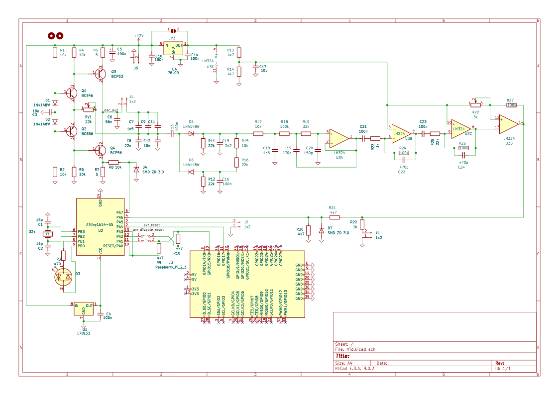
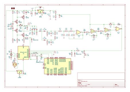
R11 22k, R15 10k, C15 100n, C19 470, C20 150p, R24 100, U33 LM324, C22 470p, C24 470p, U34, R25 1k, R26 100, R22 1k, R20 47, R21 47, PA7, PA6, PA5, PA4, PA3, PA2, PA1, PA0, RESET/PA0, U2 ATtiny1614-SS, PB0 bis PB7, PB1 bis PB7, GND, 3v3, 3v3, GND, GND, GND, GND
in „[VS] Platine RFID - Leser“ · Markt · · Schaltpläne
-
Datei
IR12roll.asm
neben den vom Bausatz bereitgestellten Ausgängen alle vom ;Bausatz nicht genutzten Portpins des ATTiny2313 zur Verfügung. .include "tn2313def.inc" ;feste Konstanten: .equ clock=1000000 ;1MHz Taktfrequenz .equ signal=pd2 ;Signaleingang .equ led1=pd3 ;Empfangs-LED-Ausgang .equ shift0=0b1111111111100000
in „8-Kanal IR-Fernbedienungs-Bausatz IRK8“ · Mikrocontroller und Digitale Elektronik ·
-
Datei
USI-TWI-Master_Test.asm
.include "tn26def.inc" ; Deklarationen für ATtiny26 .cseg ; Programm-Flash rjmp init ; Reset-Einsprung .org 0x001 ; INT0 Interrupt rjmp twi_send .org 0x006 ; Timer0 OVF Interrupt rjmp twi_send .org 0x00C ; Interrupteinsprünge
in „TWI Master mit USI, Stop condition geht nicht (AVR)“ · Mikrocontroller und Digitale Elektronik ·
-
Datei
AVR.html
" rowspan="1" style="width: 8.485%;" class="hcp11" width="8.485%"> <p class="hcp2" align="right">ATtiny26</p> </td> <td colspan="1" rowspan="1" style="width: 6.776%;" class="hcp13" width="6.776%"> <p class="hcp14" align="center"><span class="hcp15">a</span></p> </td> <td colspan="1" rowspan="1" style
in „Billige Alternative zu AVR STK 500 oder Wie brenne ich günstig mein Programm auf den Mikrochip?“ · Mikrocontroller und Digitale Elektronik ·
-
Datei
DeviceList.txt
DIP40) ATMEGA8515(PLCC44) ATMEGA8515(TQFP44) ATMEGA8535(DIP40) ATMEGA8535(PLCC44) ATMEGA8535(TQFP44) ATtiny2313 ATtiny2313V ATTINY11 ATTINY12 ATTINY13 ATTINY24(PDIP14) ATTINY24(SOIC14) ATTINY44(PDIP14) ATTINY44(SIOC14) ATTINY84(PDIP14) ATTINY84(SOIC14) ATTINY24V(PDIP14) ATTINY24V(SOIC14) ATTINY44V(PDIP14
in „[V] Genius G540 EPROM/Flash/uC Programmer (USB)“ · Markt ·
-
PDF
Schaltplan.pdf
1 36 35 32KHZ SCL 34 33 2 15 SDA 32 31 12V GND VCC VCC VCC SDA 30 29 E 3 INT VBAT 14 VBAT 28 27 T 26 25 O 4 RST GND 13 24 23 E + C1 3.3V 22 21 R 5 12 20 19 3300uf P$1 P$8 18 17 6 11 16 15 P$2 P$7 C2 14 13 LSP4 +VIN -VIN -VOUT +VOUT REMOTE 7 P$3 P$6 10 12 11 GND 100nF 10 9 8 P$4 P$5 9 VCC 8 7 SHUTDOWN
in „Raspi Shield - so in Ordnung?“ · Mikrocontroller und Digitale Elektronik ·
-
Datei
USI_TWI_Master.c
Supported devices : All device with USI module can be used. * The example is written for the ATmega169, ATtiny26 and ATtiny2313 * * AppNote : AVR310 - Using the USI module as a TWI Master * * Description : This is an implementation of an TWI master using * the USI module as basis. The implementation assumes
in „Butterfly USI als TWI Master verwenden“ · Mikrocontroller und Digitale Elektronik ·
-
Datei
USI_TWI_Master.c
Supported devices : All device with USI module can be used. * The example is written for the ATmega169, ATtiny26 and ATtiny2313 * * AppNote : AVR310 - Using the USI module as a TWI Master * * Description : This is an implementation of an TWI master using * the USI module as basis. The implementation assumes
in „C-Code optimieren (passt nicht in Attiny2313) :(“ · Mikrocontroller und Digitale Elektronik ·
-
Datei
USI_TWI_Master.c
Supported devices : All device with USI module can be used. * The example is written for the ATmega169, ATtiny26 and ATtiny2313 * * AppNote : AVR310 - Using the USI module as a TWI Master * * Description : This is an implementation of an TWI master using * the USI module as basis. The implementation assumes
in „I2C ATtiny167 mit USI“ · Mikrocontroller und Digitale Elektronik ·
-
Datei
USI_TWI_Master.c
Supported devices : All device with USI module can be used. * The example is written for the ATmega169, ATtiny26 and ATtiny2313 * * AppNote : AVR310 - Using the USI module as a TWI Master * * Description : This is an implementation of an TWI master using * the USI module as basis. The implementation assumes
in „TWI mit USI nach AN-310“ · Mikrocontroller und Digitale Elektronik ·
-
Datei
USI_TWI_Master.c
Supported devices : All device with USI module can be used. * The example is written for the ATmega169, ATtiny26 and ATtiny2313 * * AppNote : AVR310 - Using the USI module as a TWI Master * * Description : This is an implementation of an TWI master using * the USI module as basis. The implementation assumes
in „Atmel AVR TWI Library - Verständnisfrage zu Pointer“ · Mikrocontroller und Digitale Elektronik ·
-
PDF
Tiefsetzsteller.pdf
PA6 4 N?C VEE 5 11 PA7 +5V HCPL3140 MOS_SOURCE 3 16 GND_2 2 1 2 6 GND GND 2k 3 4 R1 1 5 6 GND SV1 ATTINY26-16PU GND GND +12V V 1 + VIN VOUT TMA1212S GNDIN GNDOUT MOS_SOURCE GND TITLE: Tiefsetzsteller Document Number: REV: Date: 尚未保存! Sheet: 1/1 16/6/28 10:22 /Users/wangdi/Desktop/Tiefsetzsteller.sch (
in „ATtiny26 PWM mit einstellbaren Frequenz“ · Mikrocontroller und Digitale Elektronik ·
-
PDF
HV-Progger.pdf
PD6 11 R 0 L PB1 6 (T1)PD5 9 P 5 5 R 6 4 GND PB0 5 5 (T0)PD4 8 + 0 R + 20 VCC (INT1)PD3 7 T2 GND 2 ATTINY45-20P (INT0)PD2 6 BC554 0 GND (TXD)PD1 3 T1 R3 R 1 10 GND (RXD)PD0 2 PROG-1 BC546B D 2 3 4 10k E R RR1R1 1k GND TINY2313-*P* GND VCC_P R1 L 10k 10nR 1 2 0 5 8 GND 2 R 1 RC16 3 RS232 GND GND SDI SII SDO SDC 18.04.2013 13:21:26 C:\Dokumente und Einstellungen\Fossie\Eigene Dateien\eagle\HV-Programmer\HV-Progger.sch (Sheet: 1/1)
in „Einfacher Serial-HV-Fuse-Progger für AVR“ · Projekte & Code ·