-
PDF
MEGA_WiFi-R3-AT2560-ESP8266-32MB-CH340G-1.pdf
T3/INT6]PE6 7 PE5 MH2029-300Y 0805 ADC10 87 PK3[ADC11/PCINT19] [OC3C/INT5]PE5 6 PE4 1 PE0 J6 1 SCL ESP8266 Extend Port ADC9 88 PK2[ADC10/PCINT18] [OC3B/INT4]PE4 5 PE3 1 2 PE1 1 2 SDA C8 PK1[ADC9/PCINT17] [OC3A/AIN1]PE3 2 2 ESP-RXD D12 ESP-RX DGND ADC8 89 PK0[ADC8/PCINT16] [XCK0/AIN0]PE2 4 3 3 PE4 3 3
in „Compilation error: exit status 1“ · Mikrocontroller und Digitale Elektronik ·
-
Datei
wetter.ino
#include <ESP8266WiFi.h> #include <stdlib.h> #include <DHTesp.h> DHTesp dht; WiFiClient client; // wenn aktiv: Meldungen per Serial // #define SERIAL // wenn aktiv: deep sleep nutzen (Hardwaremodifikation notwendig
in „ESP-01 funktioniert in Sleep-Mode nur nach 2xReset“ · Mikrocontroller und Digitale Elektronik ·
-
Datei
Mixed_Reality_Space_Forum.txt
#include <ESP8266WiFi.h> #include <PubSubClient.h> #include <SPI.h> #include <Ethernet.h> #include <PubSubClient.h> #include <MPU6050_tockn.h> #include <Wire.h> MPU6050 mpu6050(Wire); const char* ssid = ""; const
in „char in int umwandeln“ · Mikrocontroller und Digitale Elektronik ·
-
Datei
main.cpp
#ifdef ESP8266 #include <ESP8266WiFi.h> #else #include <WiFi.h> #endif #include <WiFiUdp.h> const char* ssid = "XXXXXXXX"; const char* password = "YYYYYYYYYY"; unsigned int multicastPort = 9522; // local port
in „ESP01S: TCP Server und UDP Multicast“ · Mikrocontroller und Digitale Elektronik ·
-
Datei
Test_ESP8266_DS18B20.ino
Santos Complete project details at https://RandomNerdTutorials.com https://randomnerdtutorials.com/esp8266-ds18b20-temperature-sensor-web-server-with-arduino-ide/ mit Sensor DS18B20 *********/ #include <Arduino.h> #include <ESP8266WiFi.h> #include <Hash.h> #include <ESPAsyncTCP.h> #include <ESPAsyncWebServer.h
in „HTML Anzeige - Farbe Meldetext ändern“ · Mikrocontroller und Digitale Elektronik ·
-
Datei
esp_Gleissteuerung_OK.ino
#include <ESP8266WiFi.h> #include <ESP8266WebServer.h> const char* AP_SSID = "Modellbahn_Steuerung"; const char* AP_PASS = "12345678"; ESP8266WebServer server(80); // Befehl und Antwort für die spätere Steuerung
-
Datei
DTZ_Logger_OPEN.ino
owned by Peter Rebesky and any comercial using is forbidden without approval of us (me). **/ #include <ESP8266WiFi.h> //ESP8266 Core WiFi Library #include <ESP8266WiFiMulti.h> //ESP8266 Core WiFi Library #include <DNSServer.h> #include <ESP8266WebServer.h> //Local WebServer #include "configDTZ.h" #include
in „DTZ541 mMe Datenlogger mit ESP (WEB-Sicht)“ · Mikrocontroller und Digitale Elektronik ·
-
Datei
DTZ_Logger_OPEN.ino
owned by Peter Rebesky and any comercial using is forbidden without approval of us (me). **/ #include <ESP8266WiFi.h> //ESP8266 Core WiFi Library #include <ESP8266WiFiMulti.h> //ESP8266 Core WiFi Library #include <DNSServer.h> #include <ESP8266WebServer.h> //Local WebServer #include "configDTZ.h" #include
in „DTZ541 mMe Datenlogger mit ESP (WEB-Sicht)“ · Mikrocontroller und Digitale Elektronik ·
-
Datei
DTZ_Logger_OPEN.ino
owned by Peter Rebesky and any comercial using is forbidden without approval of us (me). **/ #include <ESP8266WiFi.h> //ESP8266 Core WiFi Library #include <ESP8266WiFiMulti.h> //ESP8266 Core WiFi Library #include <DNSServer.h> #include <ESP8266WebServer.h> //Local WebServer #include "configDTZ.h" #include
in „Digitale Stromzähler auslesen und in DB speichern“ · Mikrocontroller und Digitale Elektronik ·
-
Datei
LSC_Tuerkontakt.ino
httpPort = 8083; //Fhem Daten byte host[] = { 192, 168, 178, 53 }; #include <SoftwareSerial.h> #include <ESP8266WiFi.h> #include <ESP8266mDNS.h> #include <WiFiUdp.h> #include <ArduinoOTA.h> #include <WiFiManager.h> byte IC_com(); //Ergebniss der Comm zwischen MCU und ESP String IPName =""; //Fhem device =
in „LSC Smart Connect - neues Smart Home System bei Action“ · Haus & Smart Home ·
-
Datei
Sonoff_Timer_Steuerung.ino
// Libraries #include <ESP8266WiFi.h> #include <ESP8266WebServer.h> #include <TTBOUNCE.h> #include <EEPROM.h> extern "C" { #include "user_interface.h" } //======SERVER PART====================================================== const char* ssid = "SSID"; const char* password = "PASSWORD"; ESP8266WebServer server ( 80 ); char htmlResponse[3000]; //======LOKALER PART====================================================== os_timer_t myTimer; bool tickOccured; bool timerrunning; int RelaisPin
in „2fach Timer für Kaffeemühle“ · Analoge Elektronik und Schaltungstechnik ·
-
PDF
HOW_TO_ESP8266_Maehroboter_Anbindung_V3_NEU.pdf
Gardena R40 Li mit ESP8266 verbinden und mit Loxone steuern Der Mähroboter Gardena bzw. Automower wurde ja schon vor Jahren analysiert und die HEXADEZIMAL Befehle, die wir zum steuern benötigen wurden im Mikrocontroller Forum
in „Automower G3 mit USB Diagnoseport fernsteuern?“ · Mikrocontroller und Digitale Elektronik ·
-
Datei
0001-Add_Frre_Text_Support_To_STM32.patch
wclock24h-F103.ebp @@ -226,6 +226,10 @@ <Option compilerVar="CC" /> </Unit> <Unit filename="..\src\esp8266\esp8266.h" /> + <Unit filename="..\src\freetext\freetext.c"> + <Option compilerVar="CC" /> + </Unit> + <Unit filename="..\src\freetext\freetext.h" /> <Unit filename="..\src\i2c\i2c.c"> <Option compilerVar
-
Datei
ESP_Webserver_Home_3.ino
#include <ESP8266WiFi.h> const char* ssid = "XXXXXX"; const char* password = "XXXXXX"; unsigned long ulReqcount; unsigned long ulReconncount; // Create an instance of the server on Port 80 WiFiServer server(80);
in „ESP8266 mehrere clients auf einer webseite“ · Mikrocontroller und Digitale Elektronik ·
-
Datei
Wall-E_ESP8266_v1.15.ino
modify timer #define PrgVer 1.15 // add OTA, add MQTT, add wifiMulti, add links on index page #include <ESP8266WiFi.h> #include <ESP8266WebServer.h> //#include <WiFiClient.h> #include <ESP8266WiFiMulti.h> #include <ESP8266mDNS.h> #include <ESP8266HTTPUpdateServer.h> //*************************************
in „Automower G3 mit USB Diagnoseport fernsteuern?“ · Mikrocontroller und Digitale Elektronik ·
-
PDF
Arduino_Cheat_Sheet_fuer_ESP32_V3c.pdf
Umwandlung isListening () // SoftwareSerial break; <<= Links schieben mit Zuweisung // zu Uno, Nano, ESP8266 char (val) byte (val) available, read, write, print etc. Advanced I/O int (val) short (val) // Genauso wie bei Serial case 3: // wenn var = 3 >>= Rechts schieben mit Zuweisung long (val) float (
in „ESP32 Arduino Cheat Sheet (aktuell für BSP3.x)“ · Mikrocontroller und Digitale Elektronik ·
-
PDF
Arduino_Cheat_Sheet_fuer_ESP32_V3d.pdf
Umwandlung isListening () // SoftwareSerial break; <<= Links schieben mit Zuweisung // zu Uno, Nano, ESP8266 char (val) byte (val) available, read, write, print etc. Advanced I/O int (val) short (val) // Genauso wie bei Serial case 3: // wenn var = 3 >>= Rechts schieben mit Zuweisung long (val) float (
in „ESP32 Arduino Cheat Sheet (aktuell für BSP3.x)“ · Mikrocontroller und Digitale Elektronik ·
-
PDF
Arduino_Cheat_Sheet_fuer_ESP32_V3e.pdf
Umwandlung isListening () // SoftwareSerial break; <<= Links schieben mit Zuweisung // zu Uno, Nano, ESP8266 char (val) byte (val) available, read, write, print etc. Advanced I/O int (val) short (val) // Genauso wie bei Serial case 3: // wenn var = 3 >>= Rechts schieben mit Zuweisung long (val) float (
in „ESP32 Arduino Cheat Sheet (aktuell für BSP3.x)“ · Mikrocontroller und Digitale Elektronik ·
-
PDF
Arduino_Cheat_Sheet_fuer_ESP32_V3e_PDF_A.pdf
Umwandlung isListening () // SoftwareSerial break; <<= Links schieben mit Zuweisung // zu Uno, Nano, ESP8266 char (val) byte (val) available, read, write, print etc. Advanced I/O int (val) short (val) // Genauso wie bei Serial case 3: // wenn var = 3 >>= Rechts schieben mit Zuweisung long (val) float (
in „ESP32 Arduino Cheat Sheet (aktuell für BSP3.x)“ · Mikrocontroller und Digitale Elektronik ·
-
 Bild
Auswahlliste von ESP32-Mikrocontroller-Serien
Series Check All ESP32-P4 ESP32-H2 ESP32-C6 ESP32-C61 ESP32-C5 ESP32-C3(including ESP8685) ESP32-C2/ESP8684 ESP32-S3 ESP32-S2 ESP32 ESP8266
in „Kaufempfehlung für ESP32 + WLAN + LAN“ · Mikrocontroller und Digitale Elektronik · · Screenshots

-
Datei
cc1101_Receive.ino
Settings 0x3F, // TEST1 Various Test Settings 0x0B // TEST0 Various Test Settings }; void setup(){ #ifdef ESP32 gdo0 = 2; // for esp32! GDO0 on GPIO pin 2. #elif ESP8266 gdo0 = 5; // for esp8266! GDO0 on pin 5 = D1. #else gdo0 = 6; // for Arduino! GDO0 on pin 6. #endif Serial.begin(9600); Serial.println("Rx
in „ESP8266 Wemos D1 & CC1101“ · Mikrocontroller und Digitale Elektronik ·
-
Datei
main.cpp
#include <Arduino.h> #include <pcf8574_esp.h> #include <PolledTimeout.h> #define PCF_INT_PIN D5 #define PCF_DEBOUNCE_MS 50 #define PCF_INPUT1 3 #define PCF_INPUT2 2 #define PCF_INPUT3 1 #define PCF_INPUT4 0 #define INPUT_CHECK_INTERVAL 10 PCF857x pcf8574(0x20, &Wire); esp8266::polledTimeout::oneShotFastMs debounceTime(PCF_DEBOUNCE_MS); esp8266::polledTimeout::periodicFastMs checkInputs(INPUT_CHECK_INTERVAL); uint8_t pins = 0; void setup() { Serial.begin(115200); pinMode
in „ESP8266 mit PCF8574 und Taster - Interrupt vom PCF "spinnt"?“ · Mikrocontroller und Digitale Elektronik ·
-
Datei
ESP_Gleissteuerung_29_10_26_A_WS_2.ino
#include <ESP8266WiFi.h> #include <ESP8266WebServer.h> void ws2812Init();// wegen ws2812 steuerung void ws2812ShowByte(uint8_t value);// wegen ws2812 steuerung const char* AP_SSID = "Modellbahn_Steuerung"; const char* AP_PASS = "12345678"; ESP8266WebServer server(80); #include <FastLED.h> #define NUM_LEDS 13 #define LED_DATA_PIN 13 // 4 ist D2 13 ist D7 CRGB leds[NUM_LEDS]; // Befehl und Antwort für die spätere Steuerung uint8_t sendByteValue
-
Datei
Neues_Textdokument__2_.txt
detected eeprom is online current eeprom version: 0x00020800 reading ir codes from eeprom DFPLAYER LOGGER ESP8266 LOGGER read rtc: Th 2018-02-15 10:35:48 esp8266 now up (- setup UDP) (- local port: 2421) (- setup server UDP) (- local port: 2424) (FIRMWARE 2.6.6) (- connected to AP) (AP FRITZ!Box Fon WLAN 7390) (MODE client) (IPADDRESS 192.168.178.41) info: ip address = 192.168.178.41 esp8266 now online --> time "192.53.103.103"<0d><0a> RTC temperature: 20 (OK time) (TIME 3727676155) (- new client) (- new client) (CMD N030000) switching power off (Exception (0):) (epc1=0x40229b14 epc2
-
Datei
DTZ_Logger_OPEN.ino
owned by Peter Rebesky and any comercial using is forbidden without approval of us (me). **/ #include <ESP8266WiFi.h> //ESP8266 Core WiFi Library #include <ESP8266WiFiMulti.h> //ESP8266 Core WiFi Library #include <DNSServer.h> #include <ESP8266WebServer.h> //Local WebServer #include "configDTZ.h" #include
in „Digitale Stromzähler auslesen und in DB speichern“ · Mikrocontroller und Digitale Elektronik ·
-
PDF
305000076A_radino_WiFi.pdf
Features Applications ● Arduino-compatible (Arduino Micro / Leonardo) ● Internet ofThings (IoT) ● Wifi ESP8266 Chip, connected via SPI-UART- ● Mobile comminications Bridge with 1151200 Baud. htp://espressif.com/en/products/esp8266/ ● Digital home network ● ESP8266 Firmware Upgrade through USB ● Mobile accessories
in „Wlan2Serial Modul für 5 euro“ · Mikrocontroller und Digitale Elektronik ·
-
PDF
EMS-ESP.pdf
r 3 URXD URXD H GPIO2 8 6 D C GPIO16 4S 1 N 1 D EMS_TX G GPIO16 GPIO16 4 + C7 GN1 GND URXD JP2 GND ESP8266 1 D 10µ N 2 G TXD 3 EMS_RX GND GND EMS-NetIO-Adapter Software: Ethersex and Danny Baumanns AddOn 29.11.14 19:44 /home/jorschiedt/eagle/ESP8266-EMS/EMS-ESP.sch (Sheet: 1/1)
-
Datei
Wall-E_ESP8266_v1.14.ino
instead of static ip #define PrgVer 1.14 // Insert refresh button, reactivate and modify timer #include <ESP8266WiFi.h> #include <ESP8266WebServer.h> #include <WiFiClient.h> #include <ESP8266mDNS.h> #include <ESP8266HTTPUpdateServer.h> //*********************************************************************
in „Automower G3 mit USB Diagnoseport fernsteuern?“ · Mikrocontroller und Digitale Elektronik ·
-
Datei
links.txt
http://www.esp8266.com/viewtopic.php?f=9&t=1871 http://www.esp8266.com/viewtopic.php?f=9&t=1871&start=40
in „WiFi Relais mit ESP8266 ESP-01 Modul (Bascom)“ · Projekte & Code ·
-
Datei
sender_esp.ino
#include <ESP8266WiFi.h> #include <espnow.h> // REPLACE WITH RECEIVER MAC Address uint8_t broadcastAddress[] = {0x58, 0xBF, 0x25, 0xD6, 0xF6, 0x8C}; #define REF_PIN 5 // Structure example to send data // Must match
in „ESP-NOW timing accuracy auf ESP8266/ESP32“ · Mikrocontroller und Digitale Elektronik ·
-
Datei
Versuch3.ino
include <CapacitiveSensor.h> #include <EasyNTPClient.h> #include <DFRobotDFPlayerMini.h> #include <ESP8266WiFi.h> #include <WiFiClient.h> #include <EEPROM.h> #include <SoftwareSerial.h> #include <WiFiUdp.h> #define DBG_OUTPUT_PORT Serial #define wpsButton D6 //GPIO2 #define Poti A0 #define touch_in D7
in „Sprechende Lampe“ · Mikrocontroller und Digitale Elektronik ·
-
PDF
esp8266player2-brd.pdf
2 D n - L u P H E D 3 L 2 t h e n e n A 19.01.2018 11:15:46 f=2.80 C:\Users\gau2hi\Documents\eagle\ESP8266\esp8266player2.brd
-
Datei
Test_ESP8266_DS18B20.ino
Santos Complete project details at https://RandomNerdTutorials.com https://randomnerdtutorials.com/esp8266-ds18b20-temperature-sensor-web-server-with-arduino-ide/ mit Sensor DS18B20 *********/ #include <Arduino.h> #include <ESP8266WiFi.h> #include <Hash.h> #include <ESPAsyncTCP.h> #include <ESPAsyncWebServer.h
in „HTML Anzeige - Farbe Meldetext ändern“ · Mikrocontroller und Digitale Elektronik ·
-
Datei
SPI_Interrupt.ino
//Add the SPI library so we can communicate with the ADXL345 sensor #include <ESP8266WiFi.h> #include <WiFiUdp.h> #include "Arduino.h" #include <SPI.h> //Assign the Chip Select signal to pin 5. int CS=5; int interruptPin=4; volatile int loopi = 0; struct dirs{ int x; int y; int z
in „ADXL345 und ESP8266: Echtzeitdatenergassung mit konstanter Abtastrate und Interrupts“ · Mikrocontroller und Digitale Elektronik ·
-
Datei
kwb23.ino
mqtt_server = "192.168.xx.yy"; // IP des MQTT Servers - z.B. fhem // Ende Individualisierungen #include <ESP8266WiFi.h> #include <ESP8266mDNS.h> #include <WiFiUdp.h> #include <ArduinoOTA.h> #include <PubSubClient.h> #include <stdio.h> #include <time.h> #define STATE_WAIT_FOR_HEADER 1 #define STATE_READ_MSG
-
 Bild
Zwei Leiterplatten und ein Software-Dashboard
Abtaumodus Aus Behälter voll/entfernt Aus Luftfeuchtigkeit 58 % Temperatur 21 °C ZUM DASHBOARD HINZUFÜGEN ESP8266 ESP-07 ESP-07S ESP-12E ESP-12F ESP-12S ESP-01S CORA0-1225W_V1.0
in „WR3 gegen ES8266 tauschen (Software/BUS)“ · Mikrocontroller und Digitale Elektronik · · Fotos

-
 Bild
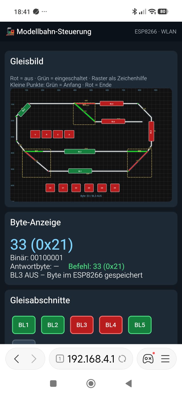
Web-Interface einer Modellbahn-Steuerung mit Gleisbild und Byte-Anzeige
Modellbahn-Steuerung ESP8266 WLAN Gleisbild Rot = aus; Grün = eingeschaltet; Raster als Zeichenhilfe Kleine Punkte: Grün = Anfang Rot = Ende 100 200 300 400 500 600 700 800 900 BL5 BL3 W3 W11 125 BL6 R E A 300 W5 BL3 400 500
in „Ki Hilft.wenn auch nicht immer“ · Offtopic · · Screenshots
-
Datei
18-002A.ino
#include <RF24Network.h> #include <RF24.h> #include <RF24Mesh.h> #include <ESP8266WiFi.h> #include <ESP8266HTTPClient.h> #define _VERSION 1005 uint32_t displayTimer = 0; // NRF24L01+ CE auf GPIO15 / Pin12 RF24 radio(15, 2); // CE, CS RF24Network network(radio); RF24Mesh mesh(radio
in „ESP8266 - Arduino - HTTP Get, ESP stürzt ab.“ · Mikrocontroller und Digitale Elektronik ·
-
Datei
OTAhandle.h
approval of us (me). **/ #ifndef OTA_HANDLE_H_ #define OTA_HANDLE_H_ #include <WiFiUdp.h> #include <ESP8266httpUpdate.h> #include "global.h" extern ESP8266WiFiMulti WiFiMulti; //*** functions in this file **************************// String getFilesFromServer(IPAddress ip, String updateServer); String
in „Digitale Stromzähler auslesen und in DB speichern“ · Mikrocontroller und Digitale Elektronik ·
-
Datei
receiver_esp.ino
#include <ESP8266WiFi.h> #include <espnow.h> #define REF_PIN 5 // Structure example to receive data // Must match the sender structure uint8_t data; // Callback function that will be executed when data is received
in „ESP-NOW timing accuracy auf ESP8266/ESP32“ · Mikrocontroller und Digitale Elektronik ·
-
Datei
WC12h_1n_284_20180221.txt
detected eeprom is online current eeprom version: 0x00020800 reading ir codes from eeprom DFPLAYER LOGGER ESP8266 LOGGER read rtc: We 2018-02-21 15:16:50 DFPlayer: SD card online DFPlayer: query software version DFPlayer: Version 0005 DFPlayer: set source device: 2 DFPlayer: set eq 0 DFPlayer: set volume 20 DFPlayer is up dfplayer is online RTC temperature: 19 esp8266 now up (- setup UDP) (- local port: 2421) (- setup server UDP) (- local port: 2424) (FIRMWARE 2.8.3a) read rtc: We 2018-02-21 15:17:45 RTC temperature: 19 read rtc: We 2018-02-21 15:18:45 RTC temperature
-
Datei
kwb13.ino
mqtt_server = "xxx.xxx.xxx.xxx"; // IP des MQTT Servers - z.B. fhem // Ende Individualisierungen #include <ESP8266WiFi.h> #include <ESP8266mDNS.h> #include <WiFiUdp.h> #include <ArduinoOTA.h> #include <PubSubClient.h> #include <stdio.h> #include <time.h> #ifndef STASSID #endif #define STATE_WAIT_FOR_HEADER 1
-
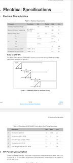
 Bild
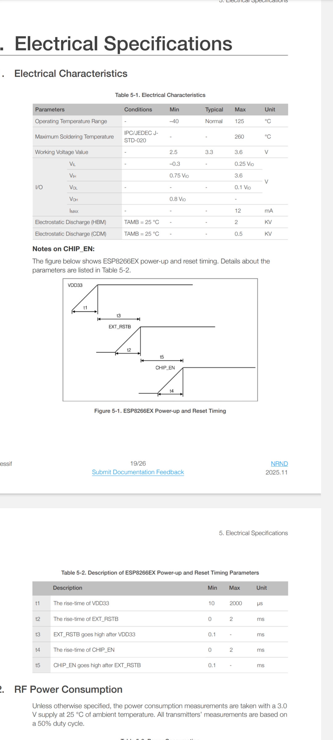
Ausschnitt aus einem Datenblatt mit elektrischen Spezifikationen
Electrostatic Discharge (HBM) TAMB = 25 °C 2 KV Electrostatic Discharge (CDM) TAMB = 25 °C 0.5 KV Figure 5-1. ESP8266EX Power-up and Reset Timing Table 5-2. Description of ESP8266EX Power-up and Reset Timing Parameters Description Min Max Unit t1 The rise-time of VDD33 10 2000 µs t2 The rise-time of EXT_RSTB 0
in „ESP8266 D1 Mini + Relaismodul: Relais bleibt bei D1 dauerhaft eingeschaltet“ · Mikrocontroller und Digitale Elektronik · · Screenshots
-
PDF
user-mannual-for-esp-12e-motor-shield.pdf
2 User Mannual for ESP-12E Motor Shield Introduction ESP-12E Motor Shield is designed and developed by Shenzhen Doctors of Intelligence & Technology (SZDOIT). This large current motor driven module can compatible with ESP12E
in „Motorshield 12e / ESP8266“ · Mikrocontroller und Digitale Elektronik ·
-
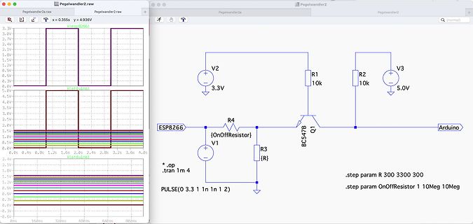
 Bild
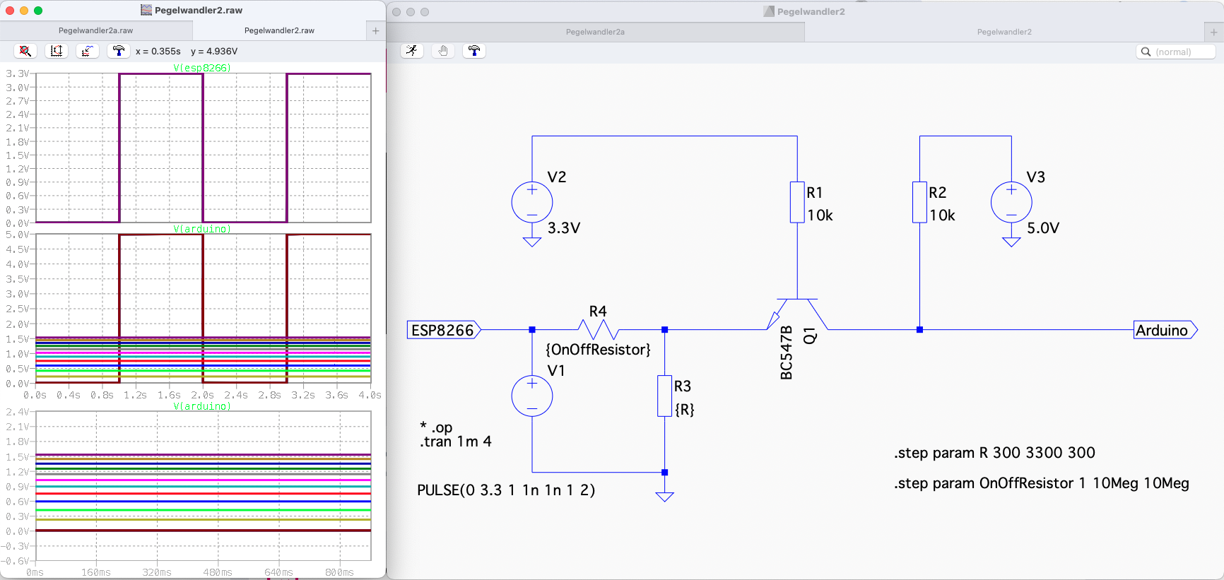
Schaltplan und Oszilloskop-Simulation in LTspice
Pegelwandler2.raw Pegelwandler2 x = 0.355s y = 4.936V V(esp8266) 3.3V 3.0V 2.7V 1.0V 1.5V 1.2V 0.9V 0.6V 0.3V 0.0V 5.0V 4.5V 4.0V 3.5V 3.0V 2.5V 2.0V 1.5V 1.0V 0.5V 0.0V V(arduino) 2.4V 2.1V 1.8V 1.5V 1.2V 0.9V 0.6V 0.3V 0.0V -0.3V 0s 0.4s 0.8s 1.2s 1.6s 2.0s 2.4s 2.8s 3.2s 3.6s 4.0s 800ms 640ms 480ms 320ms 160ms 0s V2 3.3V R1 10k V3 5.0V R2 10k ESP8266 {OnOffResistor} R4 Q1 BC547 R3 {R} V1 Arduino .op .tran 1m 4 .step param R 300 3300 300 .step param OnOffResistor 1 10Meg 10Meg PULSE(0 3.3 1n 1n 1n 2)
in „NPN-Transistorschaltung "umdrehen"“ · Analoge Elektronik und Schaltungstechnik · · Screenshots
-
Datei
ESP8266_WifiDmx.ino
#include "Arduino.h" #include <ESP8266WiFi.h> #include <ESP8266WebServer.h> #include <ESPDMX.h> #include <EEPROM.h> /* debug request string on web page */ #define WEBSITE_DEBUG_REQUEST 0 /* pin definitions for LEDs and cfg-reset */ #
in „FreeRTOS - ESP8266 "vergisst" Bytes beim Senden über SPI“ · Mikrocontroller und Digitale Elektronik ·
-
Datei
ESP8266_WifiDmx.c
#include "Arduino.h" #include <ESP8266WiFi.h> #include <ESP8266WebServer.h> #include <ESPDMX.h> #include <EEPROM.h> /* debug request string on web page */ #define WEBSITE_DEBUG_REQUEST 0 /* pin definitions for LEDs and cfg-reset */ #
in „FreeRTOS - ESP8266 "vergisst" Bytes beim Senden über SPI“ · Mikrocontroller und Digitale Elektronik ·
-
Datei
esp8266_wifi_duck.ino
#include <ESP8266WiFi.h> #include <FS.h> #include <ESP8266mDNS.h> #include <ESPAsyncTCP.h> #include <ESPAsyncWebServer.h> #include <SPIFFSEditor.h> #include <EEPROM.h> #include "data.h" #include "Settings.h" #define
in „Arduino IDE Kompilierungsfehler“ · Mikrocontroller und Digitale Elektronik ·
-
PDF
Projektuebersicht_ESP8266_Wassermelder.pdf
Wassermelder mit ESPHome und Homeassistant Problembeschreibung: Wenn die Sonde im Wasser liegt, wechselt der ESP-01 nicht zuverlässig seinen Status. Nur wenn man die Sonde tief ins Wasser eintaucht, erfolgt der Zustandswechsel am ESP-01. Spannungsmessung zwischen GND und GPIO2 ergab: - Sonde nicht im Wasser (Zustand „trocken“): U=3,12 V - Sondenkontakte galvanisch kurzgeschlossen (soll Zustand „nass“ simulieren): U=0 V, blaue LED an GPIO2 leuchtet - Sonde im Wasser und eingetaucht: U=1,54 V (diese Spannung scheint der Schwellwert zwischen den beiden Zuständen „nass“ und „trocken“ zu sein. Bild
in „ESP8266 Wassermelder ESPHome Homeassistant“ · Mikrocontroller und Digitale Elektronik ·
-
Datei
ESP8266_WiFiClient.ino
#include <ESP8266WiFi.h> #include <lwip/icmp.h> #include <lwip/raw.h> const char* ssid = "x"; const char* password = "y"; u8_t packedReceived(NULL, raw_pcb * pcb, pbuf * packetBuffer, const ip_addr_t * addr) { Serial.println
in „Wie kann man mit ESP8266/ArduinoIDE auf IP-Pakete zugreifen?“ · Mikrocontroller und Digitale Elektronik ·