-
Datei
high_speed_quad_decoder_8bit.asm
* minimum baud rate 97kbaud ;* ;* this example uses 4,88kHz frame rate and 250kbaud 8N1 ;* ;* ;* ATtiny2313 @ 20 MHz ;* ;* Pinout ;* ;* PB0: A0 ;* PB1: A1 ;* PB2: A2 ;* PB3: A3 ;* PB4: B0 ;* PB5: B1 ;* PB6: B2 ;* PB7: B3 ;* PD1: UART TXD ;* ;***************************************************************************************** .include "tn2313def.inc" .equ F_CPU = 20000000 .equ BAUD = 250000 ; calculations .equ UBRR_VAL = ((F_CPU+BAUD*8)/(BAUD*16)-1) ; clever rounding .equ BAUD_REAL = (F_CPU/(16*(UBRR_VAL+1))) ; real baud rate .equ BAUD_ERROR
in „Versetzte Rechtecksignale auswerten, kein drehgeber“ · Mikrocontroller und Digitale Elektronik ·
-
Datei
wrtilty.c
/* wrtilty.c * * Code to control a motor and a servo using an ATTiny2313. The ATTiny receives * commands through the UART and sets its PWM or servo pulse accordingly. * * John Boiles * 31 October 2008 */ #include <inttypes.h> #include <avr/io.h> #include <avr/interrupt.h
in „Attiny2313 macht Probleme“ · Mikrocontroller und Digitale Elektronik ·
-
PDF
freq_zaehler_attiny.pdf
2-2 for an example. A non-inclusive list of Atmel AVR devices with this feature includes: Atmel ATtiny10, ATtiny13, ATtiny20, ATtiny26, ATtiny28, ATtiny2313, ATmega48/88/168, ATmega8, ATmega16, ATmega32, ATmega8515/8535, ATmega162, ATmega164/324/644/ 1284, and ATmega165/325/3250/645/6450. 2 AVR205 8365A-AVR-01/11 AVR205 Figure 2-2. Atmel ATtiny13A pinout. 3 Measurement principle In this application note, the “gate-open” interval was chosen to be 0.1s, or 100ms, and so the signal to be measured will clock a counter for this time interval,
in „Frequenzzähler mit ATMega32“ · Mikrocontroller und Digitale Elektronik ·
-
Datei
device2007.txt
AT89C51EC2, AT89C51IC2, AT89C51RD2, AT89C51ED2, AT89C51ID2, AT89S54, AT89S58, AT89S64, AT90S1200, AT90S2313, AT90S4414, AT90LS4414, AT90S8515, AT90LS8515, AT90S4434, AT90S8535, AT90LS8535, AT90S4434, AT90LS4434, AT90S2333, AT90S4433, ATTINY11, ATTINY12, ATTINY15L, ATTINY26, ATTINY26L, ATTINY28L, ATTINY28V, ATTINY2313, ATTINY2313V, ATMEGA8, ATMEGA8L, ATMEGA16, ATMEGA16L, ATMEGA32, ATMEGA32L, ATMEGA8515, ATMEGA8515L, ATMEGA8535, ATMEGA8535L, ATMEGA48*PDIP28, ATMEGA88*PDIP28, ATMEGA168*PDIP28, ATMEGA48V*PDIP28
in „24C04 beschreiben und auslesen“ · Mikrocontroller und Digitale Elektronik ·
-
Datei
IR8_V12_SAA3008.asm
/* Alternativ-Firmware für IR8-Bausatz Version 1.2 von Pollin Der ATTiny2313 sollte im Originalzustand gefust sein, also mit aktiviertem internen 8MHz-RC-Oszillator. Achtung: Der zum Bausatz gehörende ATTiny2313 ist auf 4MHz gefust. Der Zustand der CKDIV8-Fuse ist egal,
in „Quellcode für den Pollin Fernsteuer Bausatz“ · Mikrocontroller und Digitale Elektronik ·
-
Datei
Laufschr.asm
*************************** ; Test fuer LCD Laufschrift ; - - - - - - - - - - - - - - - - ; MCU: Attiny4313 (resp. 2313) ; MCU clock: STK500-Board (unkritisch bis ca.4MHz) ; LCD 2x16; Vierbitmodus ; - - - - - - - - - - - - - - - - ; PortD LCD Ausgabe: R/Wquer=GND ; PD7 PD6 PD5 PD4 PD3 PD2 PD1 PD0 ; n
in „LCD Lauftext Atmega8“ · Mikrocontroller und Digitale Elektronik ·
-
Datei
fuse.c
programmable attinys * . reset hi-low fuses to factory default on target devices * . layout to drop-on attiny13, attiny25/45/85 8 pin devices targets * . attiny24/44/84 targets needs additional breadboard and jumper wires * . standalone operations, fuses show on 7 segment display * * . project fuse setting * avrdude -c ponyser -P /dev/ttyS0 -p t2313 -V -U lfuse:w:0xe4:m -U hfuse:w:0xdf:m -U efuse:w:0xff:m * * . parts list * . attiny2313 * . 4x7 segment LED display * . 1k resistor x 2 * . 2n2222 NPN transistor or equivalent * . 78L05 * . mini breadboard
in „Attiny85 neu verfust?“ · Mikrocontroller und Digitale Elektronik ·
-
Datei
fuse.c
programmable attinys * . reset hi-low fuses to factory default on target devices * . layout to drop-on attiny13, attiny25/45/85 8 pin devices targets * . attiny24/44/84 targets needs additional breadboard and jumper wires * . standalone operations, fuses show on 7 segment display * * . project fuse setting * avrdude -c usbasp -P usb -p t2313 -V -U lfuse:w:0xe4:m -U hfuse:w:0xdf:m -U efuse:w:0xff:m * * . parts list * . attiny2313 * . 4x7 segment LED display * . 1k resistor x 2 * . 2n2222 NPN transistor or equivalent * . 78L05 * . mini breadboard
in „Attiny85 neu verfust?“ · Mikrocontroller und Digitale Elektronik ·
-
Datei
high_speed_quad_decoder_8bit.asm
2kHz ;* minimum baud rate 97kbaud ;* ;* this example uses 3kHz frame rate and 250kbaud 8N1 ;* ;* ;* ATtiny2313 @ 20 MHz ;* ;* Pinout ;* ;* PB0: A0 ;* PB1: A1 ;* PB2: A2 ;* PB3: A3 ;* PB4: B0 ;* PB5: B1 ;* PB6: B2 ;* PB7: B3 ;* PD1: UART TXD ;* ;***************************************************************************************** .include "tn2313def.inc" .equ F_CPU = 20000000 ; CPU clock, Hz .equ BAUD = 250000 ; Baud rate for UART .equ FRAME = 3000 ; frame rate for data packet ; calculations .equ UBRR_VAL = ((F_CPU+BAUD*8)/(BAUD*16)-1) ; clever
in „Versetzte Rechtecksignale auswerten, kein drehgeber“ · Mikrocontroller und Digitale Elektronik ·
-
Datei
PowerMCU.asm
*************************************** ;* I2C slave CPU c2012 by Vladislav Shapovalov * ;* CPU: ATtiny2313 * ;* Clock: INT 8 MHz 3dfilm@mail.ru * ;!!!!!!!!!!!!! SCL DDR and PORT are ALWAYS =1 !!!!!!!!!!!!!!!!! * ;!!!!!!!!!!!!! SDA PORT are ALWAYS =1 !!!!!!!!!!!!!!!!! * ;*****************************
in „I2C IO-Expander mit mind. 4Bits zur freien Adressvergabe.“ · Mikrocontroller und Digitale Elektronik ·
-
PDF
AVR053.pdf
4.0, and 8.0 3.0 ATmega8535 1.0, 2.0, 4.0, and 8.0 4.0 ATmega162 8.0 X X 4.0 ATmega169 8.0 X X 4.1 ATtiny13 4.8 and 9.6 X X 4.2 ATtiny2313 4.0 and 8.0 X X 5.0 ATmega48 8.0 X X Note: 1. The prescaler register is in these devices are named XDIV. Version 1.x oscillators This version is the earliest internal
in „OSCCAL für 8MHz ?!? be ATTiny26“ · Mikrocontroller und Digitale Elektronik ·
-
PDF
AVR053.PDF
4.0, and 8.0 3.0 ATmega8535 1.0, 2.0, 4.0, and 8.0 4.0 ATmega162 8.0 X X 4.0 ATmega169 8.0 X X 4.1 ATtiny13 4.8 and 9.6 X X 4.2 ATtiny2313 4.0 and 8.0 X X 5.0 ATmega48 8.0 X X Note: 1. The prescaler register is in these devices are named XDIV. Version 1.x oscillators This version is the earliest internal
in „Osccal für EEPROM bei mega8535 mit Quarz“ · Mikrocontroller und Digitale Elektronik ·
-
Datei
tm16xx.c
Anode und zusaetzlichem Tasteninterface. Geeignet fuer: TM1651, TM1637 MCU : alle AVR ( getestet ATtiny85, ATtiny2313, ATtiny44, ATmega8, ATmega328p ) F_CPU : 8 MHz intern Pinbelegung Controller TM16xx --------------------------- PB1 CLK PB0 DIO CLK und DIO sind mit jeweils 2,2 kOhm Pop-Up Wider- staenden
in „Siebensegment und Tasten ansteuern mit TM1651 \ TM1637“ · Projekte & Code ·
-
Datei
attiny25.c
/******************************************************* Projekt: Aetzwanne Version : ATTiny25 - 1 Erstellt: 20.09.2016 Letze Änderung: 25.09.2016 Chip: Attiny25 mit internen 8.0 MHz *******************************************************/ /// Header-Dateien/// #include <io.h> #include <delay.h
in „AVR ADC auswerten klappt nicht“ · Mikrocontroller und Digitale Elektronik ·
-
Datei
dds.asm
********* ; ;Description ; ; Poor-mans DDS Synthesizer ; ; Author = Jesper Hansen ; Target = AT90S2313 / ATTiny2313 ; Date = 2001-02-15 ; ; Code is written for use with AVR-GCC in assembler mode ; flag: -x assembler-with-cpp ; ; ; PB0..7 = D/A Data out ; ; PD0 RXD ; PD1 TXD ; PD2..6 not used ; ;*****
in „ASM von MiniDDS in WinAVR kompilieren. Wie?“ · Mikrocontroller und Digitale Elektronik ·
-
Datei
high_speed_quad_decoder_8bit.asm
rate 414kbaud @ F_CPU = 20 MHz ;* ;* this example uses 7kHz frame rate and 625kbaud 8N1 ;* ;* ;* ATtiny2313 @ 20 MHz ;* ;* Pinout, must stay this way to make the trick work! ;* ;* PB0: A0 ;* PB1: A1 ;* PB2: A2 ;* PB3: A3 ;* PB4: B0 ;* PB5: B1 ;* PB6: B2 ;* PB7: B3 ;* PD1: UART TXD ;* ;***************************************************************************************** .include "tn2313def.inc" .equ F_CPU = 20000000 ; CPU clock, Hz .equ BAUD = 625000 ; Baud rate for UART .equ FRAME = 7000 ; frame rate for data packet ; calculations .equ UBRR_VAL = ((F_CPU+BAUD*8)/(BAUD*16)-1) ; clever
in „Versetzte Rechtecksignale auswerten, kein drehgeber“ · Mikrocontroller und Digitale Elektronik ·
-
Datei
dude5.4arduino_avr910.txt
0x52 = (unknown) Device code: 0x53 = (unknown) Device code: 0x54 = (unknown) Device code: 0x55 = ATtiny12 Device code: 0x56 = ATtiny15 Device code: 0x57 = (unknown) Device code: 0x58 = (unknown) Device code: 0x59 = (unknown) Device code: 0x5a = (unknown) Device code: 0x5b = (unknown) Device code: 0x5c = (unknown) Device code: 0x5d = (unknown) Device code: 0x5e = ATtiny2313 Device code: 0x5f = (unknown) Device code: 0x60 = ATMEGA161 Device code: 0x61 = (unknown) Device code: 0x62 = (unknown) Device code: 0x63 = ATMEGA162 Device code: 0x64 = ATMEGA163 Device code:
in „avrdude - Probleme unter Mac OS X 10.7 (Lion)“ · Mikrocontroller und Digitale Elektronik ·
-
Datei
dude5.6_avr910.txt
0x52 = (unknown) Device code: 0x53 = (unknown) Device code: 0x54 = (unknown) Device code: 0x55 = ATtiny12 Device code: 0x56 = ATtiny15 Device code: 0x57 = (unknown) Device code: 0x58 = (unknown) Device code: 0x59 = (unknown) Device code: 0x5a = (unknown) Device code: 0x5b = (unknown) Device code: 0x5c = (unknown) Device code: 0x5d = (unknown) Device code: 0x5e = ATtiny2313 Device code: 0x5f = (unknown) Device code: 0x60 = ATMEGA161 Device code: 0x61 = (unknown) Device code: 0x62 = (unknown) Device code: 0x63 = ATMEGA162 Device code: 0x64 = ATMEGA163 Device code:
in „avrdude - Probleme unter Mac OS X 10.7 (Lion)“ · Mikrocontroller und Digitale Elektronik ·
-
Datei
dude54arduino.txt
0x52 = (unknown) Device code: 0x53 = (unknown) Device code: 0x54 = (unknown) Device code: 0x55 = ATtiny12 Device code: 0x56 = ATtiny15 Device code: 0x57 = (unknown) Device code: 0x58 = (unknown) Device code: 0x59 = (unknown) Device code: 0x5a = (unknown) Device code: 0x5b = (unknown) Device code: 0x5c = (unknown) Device code: 0x5d = (unknown) Device code: 0x5e = ATtiny2313 Device code: 0x5f = (unknown) Device code: 0x60 = ATMEGA161 Device code: 0x61 = (unknown) Device code: 0x62 = (unknown) Device code: 0x63 = ATMEGA162 Device code: 0x64 = ATMEGA163 Device code:
in „avrdude - Probleme unter Mac OS X 10.7 (Lion)“ · Mikrocontroller und Digitale Elektronik ·
-
Datei
pwm.txt
***************** ' Fading aller Farben einer RGB Led mit common Anode (im Code aenderbar) ' auf ATtiny13 an Port PB0 PB1 PB2 durch Soft PWM, da der Tiny13 nur ' zwei Hardware PWM besitzt (OC0A und OC0B). ' Die RGB Led kann natürlich auch durch einzelne Leuchtdioden ersetzt werden. ' Bei mir steuern
in „"anfänger" 2x3 pwm?“ · Mikrocontroller und Digitale Elektronik ·
-
Datei
wrtilty.c
/* wrtilty.c * * Code to control a motor and a servo using an ATTiny2313. The ATTiny receives * commands through the UART and sets its PWM or servo pulse accordingly. * * John Boiles * 31 October 2008 */ #include <inttypes.h> #include <avr/io.h> #include <avr/interrupt.h
in „Stromstärke steuern“ · Analoge Elektronik und Schaltungstechnik ·
-
Datei
IR.asm
receiver * ; * * ; * ( protocol name "unknown" ) * ; * * ; ************************************** ; ATtiny2313 @ 4 mhz .include "attn2313.inc" ; rc bit timing: ; start bit ~ 4ms ; zero bit ~ 2ms ; one bit ~ 1ms .def rctcnt = r20 .equ RC_OVER = 0x58 .equ RC_START = 0x38 .equ RC_MAX = 0x28 .equ RC_MID = 0x18
-
Datei
pt_v2.1.bas
********************* '****** Define Hardware *************************************** $regfile = "2313def.dat" 'für attiny2313 $crystal = 8000000 'für 8MHz Quarz '****** Systemparameter setzen ************************************** Dim A As Word Dim B As Byte A = 1 Ddrb = &B11111111 Ddrd = &B11111011
in „Pizzatimer mit Timerproblem“ · Mikrocontroller und Digitale Elektronik ·
-
PDF
AVR042_Hardware_Design_Considerations_doc2521.pdf
target application board so that the ISP connectors can be accessed easily. Note: 1. Except the ATtiny10, ATtiny11 and ATtiny28. On most devices the ISP interface is located on the same pins as the SPI interface. However, there are exceptions from this rule, e.g. the ATmega103 and the ATmega128 do not
in „Atmega 8A PU“ · Mikrocontroller und Digitale Elektronik ·
-
Datei
USI_SPI_SLAVE.asm
******************************************************* ;* * ;* * ;* Controller-Typ: testet with ATtiny2313 * ;* Taktfrequenz: unknown * ;* * ;* * ;* Autor: Steffen Hoerhold * ;* Date: 15.10.2012 * ;* Version: 1.0 * ;* Chip ID: ---- * ;* * ;*************************************************************************** .include "tn2313def.inc" ;***** Register-Variablen .def SREG_SAVE = r0 ; Sicherungskopie des SREG-Registers im Interrupt ; Konstanten .equ SPI_RD_BYTES = 12 ; zu empangene Bytes per SPI ; Flags in GPOIR0 .equ SPI_ON
in „SPI Kopplung von ATmega8 und ATtiny 2313“ · Projekte & Code ·
-
Datei
USI_SPI_SLAVE.asm
******************************************************* ;* * ;* * ;* Controller-Typ: testet with ATtiny2313 * ;* Taktfrequenz: unknown * ;* * ;* * ;* Autor: Steffen Hoerhold * ;* Date: 15.10.2012 * ;* Version: 1.0 * ;* Chip ID: ---- * ;* * ;*************************************************************************** .include "tn2313def.inc" ;***** Register-Variablen .def SREG_SAVE = r0 ; Sicherungskopie des SREG-Registers im Interrupt ; Konstanten .equ SPI_RD_BYTES = 12 ; zu empangene Bytes per SPI ; Flags in GPOIR0 .equ SPI_ON
in „[ASM] USI tiny SPI Slave im Interrupt Mode“ · Projekte & Code ·
-
Datei
rc.c
a-netz.de> * * Implement functions of an infrared remote control and RC5 protocol with an * Atmel ATTiny 2313. * * This program is free software; you can redistribute it and/or modify * it under the terms of the GNU General Public License as published by * the Free Software Foundation; either version
in „RC5-Sender Andreas Schröder; wie compiliert man richtig?“ · Mikrocontroller und Digitale Elektronik ·
-
Datei
bootloader.py
" % (i>>8, i & 0xff) self.send_command(self.SIGNATURE) i = self.readval() targets = { 0x1e9007: "ATtiny13", 0x1e910A: "ATtiny2313", 0x1e9206: "ATtiny45", 0x1e9205: "ATmega48", 0x1e9307: "ATmega8", 0x1e9403: "ATmega16", 0x1e9406: "ATmega168", 0x1e9502: "ATmega32", 0x1e9609: "ATmega644", 0x1e9802: "ATmega2561
in „UART Bootloader ATtiny13 - ATmega644“ · Projekte & Code ·
-
Datei
Sleep.asm
; Headerdatei fuer den AVR-Typ .NOLIST .include "tn2313def.inc" ; Header fuer den ATTINY2313 .LIST ; ; ============================================ ; H A R D W A R E I N F O R M A T I O N E N ; ============================================ ; ; [Hier alles
in „Sleep beim Attiny2313 und erwacht nimmer mehr“ · Mikrocontroller und Digitale Elektronik ·
-
Datei
adude-log.txt
avrdude -C/home/op/WORK/uC/Arduino_main/0IDE/GM_Tiny/hardware/tools/avrdude.conf -v -v -v -v -pattiny2313 -cavrisp -P/dev/ttyACM0 -b19200 -Uflash:r:/home/op/geiger/tiny/Programming_Tiny/work/GMread_01.hex:i avrdude: Version 5.11, compiled on Sep 7 2011 at 19:34:16 Copyright (c) 2000-2005 Brian Dean, http
in „Pollin Geigerzähler Bericht“ · Mikrocontroller und Digitale Elektronik ·
-
Datei
high_speed_quad_decoder_16bit.asm
* minimum baud rate 687baud ;* ;* this example uses 100 Hz frame rate and 19200baud 8N1 ;* ;* ;* ATtiny2313 @ 20 MHz ;* ;* Pinout ;* ;* PB0: A0 ;* PB1: A1 ;* PB2: A2 ;* PB3: A3 ;* PB4: B0 ;* PB5: B1 ;* PB6: B2 ;* PB7: B3 ;* PD1: UART TXD ;* ;***************************************************************************************** .include "tn2313def.inc" .equ F_CPU = 20000000 ; CPU clock, Hz .equ BAUD = 19200 ; Baud rate for UART .equ FRAME = 100 ; frame rate for data packet ; calculations .equ UBRR_VAL = ((F_CPU+BAUD*8)/(BAUD*16)-1) ; clever
in „Versetzte Rechtecksignale auswerten, kein drehgeber“ · Mikrocontroller und Digitale Elektronik ·
-
Datei
Synth.asm
.nolist .include "tn2313def.inc" ; Define device ATtiny2313 .list ; ***Konstanten*** .equ F_CPU = 10000000 .equ F_ICR = 256 .equ PWM = F_CPU/F_ICR .equ BAUD = 31250 .equ BRC = (F_CPU/16/BAUD)-1 ; ***Defs*** .def rsreg = r15
in „Attiny2313 Timer16 Bit, Normal Mode, unsauber“ · Mikrocontroller und Digitale Elektronik ·
-
Datei
high_speed_quad_decoder_16bit.asm
2000 baud @ F_CPU = 20 MHz ;* ;* this example uses 100 Hz frame rate and 19200baud 8N1 ;* ;* ;* ATtiny2313 @ 20 MHz ;* ;* Pinout, must stay this way to make the trick work! ;* ;* PB0: A0 ;* PB1: A1 ;* PB2: A2 ;* PB3: A3 ;* PB4: B0 ;* PB5: B1 ;* PB6: B2 ;* PB7: B3 ;* PD1: UART TXD ;* ;***************************************************************************************** .include "tn2313def.inc" .equ F_CPU = 20000000 ; CPU clock, Hz .equ BAUD = 19200 ; Baud rate for UART .equ FRAME = 100 ; frame rate for data packet ; calculations .equ UBRR_VAL = ((F_CPU+BAUD*8)/(BAUD*16)-1) ; clever
in „Versetzte Rechtecksignale auswerten, kein drehgeber“ · Mikrocontroller und Digitale Elektronik ·
-
 Bild
Bild
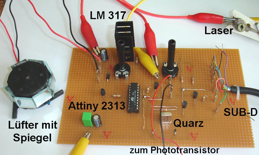
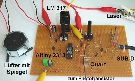
Aufbau einer Elektronikschaltung auf Lochrasterplatine
LM 317 Laser Lüfter mit Spiegel Attiny 2313 Quarz SUB-D zum Phototransistor
in „Physikprojekte“ · Offtopic · · Platinenfotos
-
 Bild
Bild
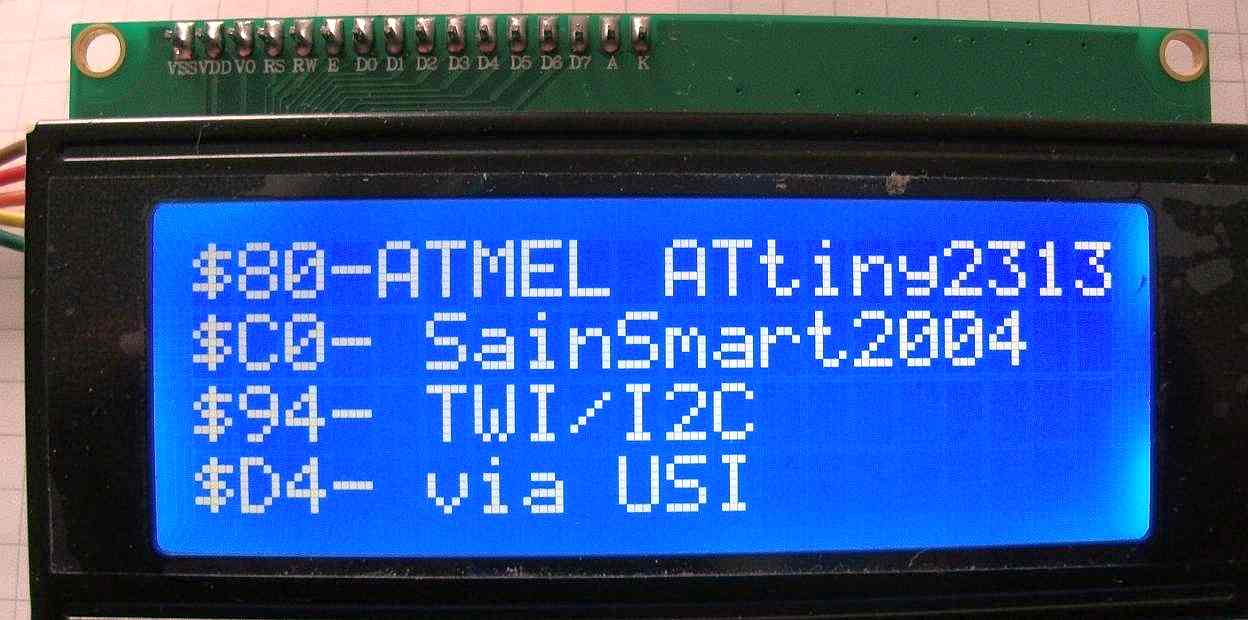
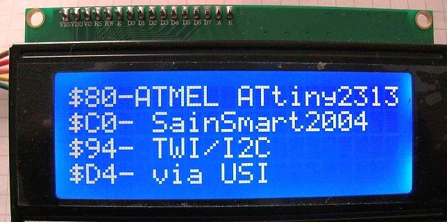
LCD-Display mit Textanzeige
$80-ATMEL ATTiny2313 $C0- SainSmart2004 $94- TWI/I2C $D4- via USI
in „Grafisches LCD Display Ersatz gesucht“ · Analoge Elektronik und Schaltungstechnik · · Fotos
-
PDF
Isp-stick-pcb.pdf
X1 C1 20pF 3 ATtiny2313 2 1 12MHz C2 20pF 22.04.11 20:23 f=5.00 /home/steih/Downloads/Isp-stick.brd
in „Bausatz AVR-ISP-Stick“ · Markt ·
-
 Bild
Bild
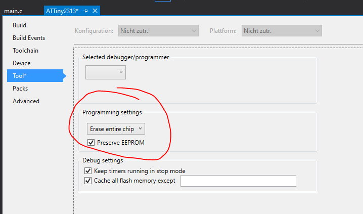
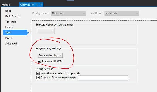
Software-Einstellungen für Mikrocontroller-Programmierung
main.c ATTiny2313* Build Konfiguration: Nicht zutr. Plattform: Nicht zutr. Toolchain Device Tool* Packs Advanced Selected debugger/programmer Programming settings Erase entire chip Preserve EEPROM Debug settings
in „Probleme mit studio4“ · Mikrocontroller und Digitale Elektronik · · Screenshots
-
Datei
sinus2313_3.asm
Tabelle ; Ein Sinussignal wird an Port B ausgegeben ; R2R-Netzwerk zur DA-Wandlung ; Testprogramm mit ATTINY2313 .include "tn2313def.inc" .equ F_CPU = 20000000 ; Systemtakt in Hz .equ BAUD = 9600 ; Baudrate ; Berechnungen .equ UBRR_VAL = ((F_CPU+BAUD*8)/(BAUD*16)-1) ; clever runden .equ BAUD_REAL = (F_CPU
in „wieder einmal dds“ · Mikrocontroller und Digitale Elektronik ·
-
Datei
farbtest.asm
; RGB_Farbtest .include "tn2313def.inc" ; Def. für ATTiny2313 .DEF areg = r17 ; Adressregister für EEPROM .DEF zael = r23 ; Zähler .DEF rot = r18 .DEF gruen = r19 .DEF blau = r20 .CSEG ; Programmsegment im Flash .org 0 rjmp init ;
in „ATTiny2313 EEPROM lesen mit Asembler“ · Mikrocontroller und Digitale Elektronik ·
-
Datei
Main_Adam.c
Created at: 05.01.2015 * //* Last Change: 05.01.2015 * //* Version: 00 * //* Uses: - * //* Processor: ATTiny2313 * //***************************************************************************** //* Parameter: - * //* * //* * //* * //************************************************************************
in „ATTiny2313 läuft nicht immer an“ · Mikrocontroller und Digitale Elektronik ·
-
Datei
snesreadout.txt
$regfile = "attiny2313.dat" $crystal = 8000000 $hwstack = 40 $swstack = 16 $framesize = 32 'CONFIG Dim A As Byte 'zum speichern Dim Edummy As Eram Byte 'dummy Dim Ae As Eram Byte 'eeprom 'START A = "01010110" Ae = A
in „Bascom: Dim as ERAM speichert nicht“ · Mikrocontroller und Digitale Elektronik ·
-
Datei
DCF77_with_Date.asm
;DCF77 Clock with extended display (14 digits, time with seconds and date) ;Controller: AT90S2313 or ATTiny2313 @ 4.194304 MHz external crystal ; ;Assemble with AVR-Studio (http://atmel.com/) only, this file contains ;directives specific for this assembler! ; ;(C) Arne Rossius, http://www.elektronik.de.vu
in „DCF77 mit SC-23 Segmente Aber wie?“ · Mikrocontroller und Digitale Elektronik ·
-
 Bild
Bild
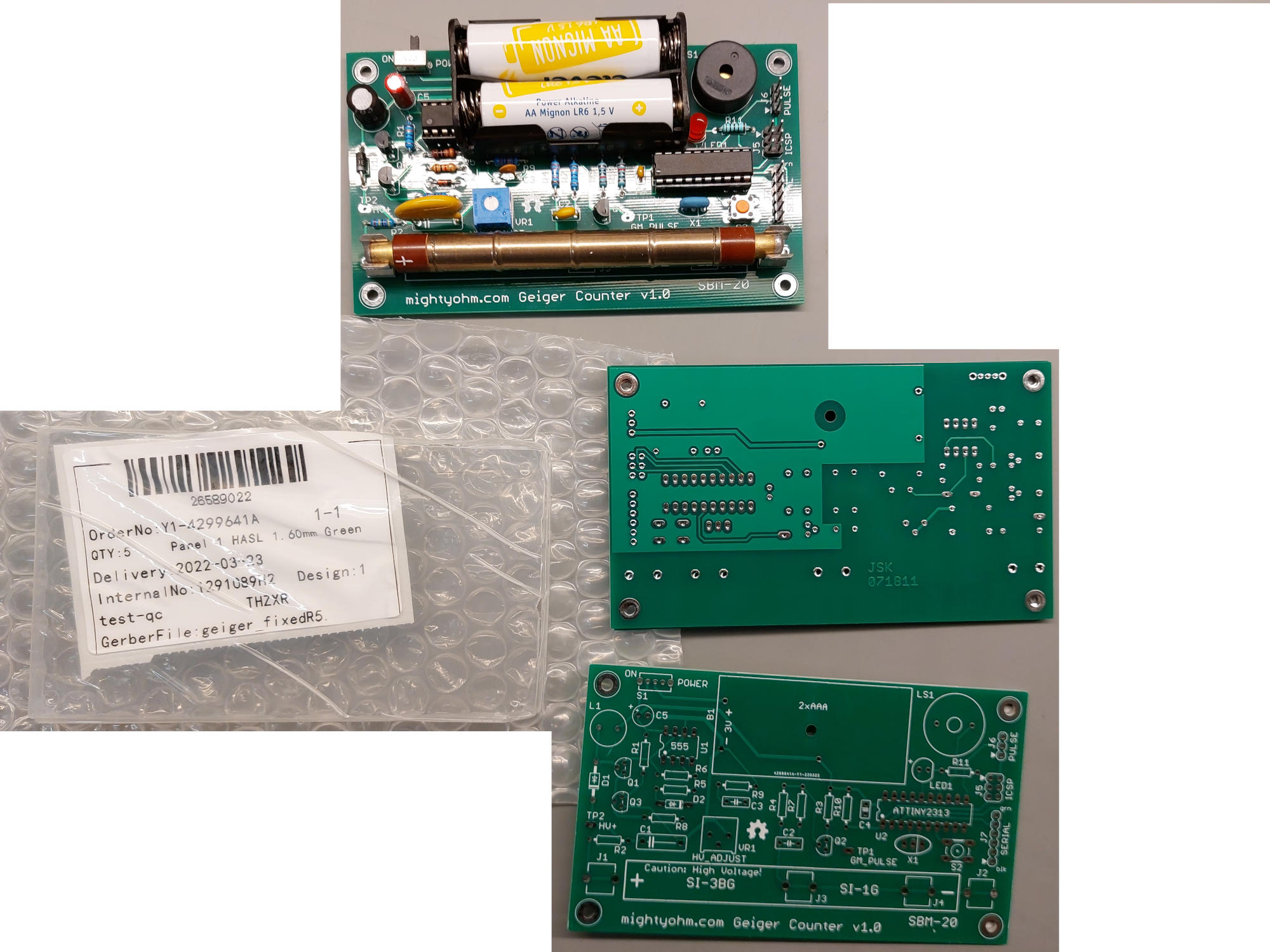
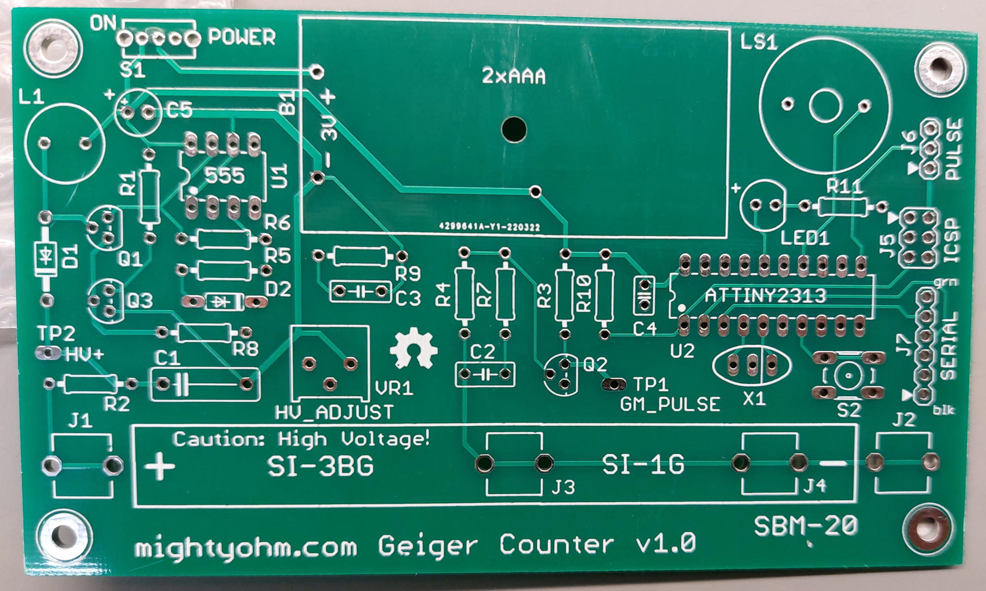
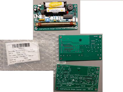
Bestückte und unbestückte Leiterplatten eines Geiger-Zählers
Green Delivery 2022-03-23 Internal No: 29U8912 Design 1 test-qc GerberFile: geiger fixedR5 SI-18 ATtiny2313 SI-20 SBM-20
in „[V] MightyOhm Geiger Counter Platinen (Nachbau)“ · Markt · · Platinenfotos
-
Datei
lcd.bas
$regfile = "Attiny2313.dat" $crystal = 1000000 Config Lcd = 16 * 2 Config Lcdpin = Pin , Db4 = Portd.0 , Db5 = Portd.1 , Db6 = Portd.2 , _ Db7 = Portd.3 , E = Portd.5 , Rs = Portd.4 Initlcd Locate 1 , 1 Lcd "Hello world
in „LCD Ansteuerung mit ATtiny 2313“ · Mikrocontroller und Digitale Elektronik ·
-
Datei
IR12roll.asm
;Infrarotempfänger mit Tiny2313 für Pollin-IR-Bausatz ;Spezialversion für den Einsatz z.B. als Rolladen-Steuerung. ;Durch Auswechseln des Pollin-AVRs gegen einen Tiny2313 mit diesem Programm ;entsteht ein völlig neuer IR-Empfänger
in „8-Kanal IR-Fernbedienungs-Bausatz IRK8“ · Mikrocontroller und Digitale Elektronik ·
-
Datei
main.h
/** Informationen über das Projekt **/ #define MMCU attiny2313 #define F_CPU 1000000UL /** Definitionen für die Statemaschine **/ #define ST_IDLE 0 // nichts zu tun #define ST_GOTDATA 1 // daten wurden empfangen #define ST_GOTCD 2 // es wurde ein befehl empfangen
in „Keine Buchstaben, aber Zahlen auf HD44780, UART, ATtiny2313“ · Mikrocontroller und Digitale Elektronik ·
-
Datei
main.c
// -------------------------------------------------------------------------- // an OC1A // ATTiny2313 // -------------------------------------------------------------------------- #include <avr/io.h> #include <avr/interrupt.h> int main() { DDRB = (1 << PB3); TCCR1A = (1 << COM1A0); // Toggle OC1A
in „38khz-Signal“ · Mikrocontroller und Digitale Elektronik ·
-
 Bild
Bild
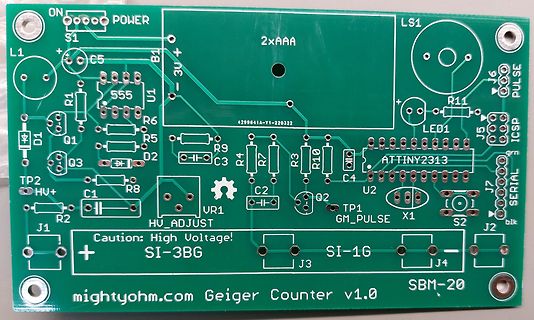
Bestückungsdruck einer Geigerzähler-Leiterplatte
ON POWER LS1 2xAAA S1 B1 -3V+ C5 R1 555 U1 R6 R5 R9 R7 R3 R10 C4 ATTINY2313 J6 PULSE J5 ICSP D1 Q1 Q3 D2 C3 R4 C2 Q2 TP1 GM_PULSE X1 S2 J2 J7 J4 J3 SI-1G SI-3BG HV_ADJUST HV+ C1 R2 J1 + Caution: High Voltage! mightyohm.com Geiger Counter v1.0 SBM-20
in „[V] MightyOhm Geiger Counter Platinen (Nachbau)“ · Markt · · Layouts
-
Datei
tiny4313.h
//Defines für Attiny2313A/4313, die in iotn4313.h fehlen #ifndef PCMSK0 #define PCMSK0 PCMSK #endif #ifndef PCIE0 #define PCIE0 5 #endif #ifndef PCIE1 #define PCIE1 3 #endif #ifndef PCIE2 #define PCIE2 4 #endif #ifndef
in „AVR (ATtiny2313): GIFR undeclared“ · Mikrocontroller und Digitale Elektronik ·
-
PDF
acl_platine_.pdf
R3 RESET0KΩ GND LM2940 100nF Attiny 2313 C4 C2 C1 VCC 3 P 0.1uF 0.33uF C5 Ω ISP 22uF n 0 7 C 0 R 1 0 1 4 1 2 3 1 R2 IRLZ34N 5*10 Ω 0 3 R 3 1L2 L 4D5 t i - A G o V Sub-D Pinbelegung: + 1 + + +12V VCC in = Pin1 ServiceLED = Pin3 GND =
in „Frage zur max. Belastung des IRLML5203“ · Analoge Elektronik und Schaltungstechnik ·