-
PDF
ch32v003_getting_started.pdf
releases/ oder https://www.jjflash.de/ch32v003/downloads (xpack-riscv-none-elf-gcc-14.2.0-3-linux-x64.tar.gz auswählen) einen Arduino UNO / nano oder ein AVR-System (ATmega328 / 168, ATmega8 oder ATtiny2313) ein im System eingerichtetes AVRDUDE Texteditor um Programme erstellen / bearbeiten zu
in „CH32V003: Selbstbauprogrammer und "Getting started"“ · Projekte & Code ·
-
Datei
Atmega644_DOGM128_094.c
/ #define LCD_RST 3 // PB3 (PIN4) -> PIN 27 PIN 39 Pin 29 // #define LCD_CS 4 // PB4 (PIN5) -> PIN 28 PIN 40 Pin 28 // #define SPI_MOSI 5 // PB5 (PIN6) -> PIN 25 PIN 37 Pin 32 // #define SPI_MISO 6 // --- ---- ----- ------ ------ // #define SPI_SCK 7 // PB7 (PIN8) -> PIN 24 PIN 36 Pin 31 */ #include
in „Library für EA-DOGM Grafikdisplays inkl. Font-Generator“ · Projekte & Code ·
-
PDF
Tiny12.pdf
Range Frequency ATtiny11L 1K - 32 2.7 - 5.5V 0-2 MHz ATtiny11 1K - 32 4.0 - 5.5V 0-6 MHz ATtiny12V 1K 64 B 32 1.8 - 5.5V 0-1.2 MHz ATtiny12L 1K 64 B 32 2.7 - 5.5V 0-4 MHz ATtiny12 1K 64 B 32 4.0 - 5.5V 0-8 MHz The ATtiny11/12 AVR is supported with a full suite of program and system development tools including
in „ATTiny12 uns SPI?“ · Mikrocontroller und Digitale Elektronik ·
-
PDF
ATTINY11_ATTINY12_ATM.pdf
Range Frequency ATtiny11L 1K - 32 2.7 - 5.5V 0-2 MHz ATtiny11 1K - 32 4.0 - 5.5V 0-6 MHz ATtiny12V 1K 64 B 32 1.8 - 5.5V 0-1.2 MHz ATtiny12L 1K 64 B 32 2.7 - 5.5V 0-4 MHz ATtiny12 1K 64 B 32 4.0 - 5.5V 0-8 MHz The ATtiny11/12 AVR is supported with a full suite of program and system development tools including
in „Attiny12 Datenblatt?“ · Mikrocontroller und Digitale Elektronik ·
-
PDF
AT90CAN128.pdf
AT90CAN32 32K Bytes 1K Byte 2K Bytes AT90CAN64 64K Bytes 2K Bytes 4K Bytes AT90CAN128 128K Bytes 4K Byte 4K Bytes 1.2 Part Description The AT90CAN32/64/128 is a low-power CMOS 8-bit microcontroller based on the AVR enhanced RISC architecture. By
in „uC + 3 Schieberegister + 7-Segmentanzeige“ · Mikrocontroller und Digitale Elektronik ·
-
Datei
All.txt
4029N DIL16 Binary/decimal up/down COUNTER 2 D9 1N4148DO35-10 1N4148DO35-10 DO35-10 DIODE 2 D8 BYV28 BYV28 SOD64-12 2 D8 1N4148 1N4148 DO35-10 DIODE 2 D7 BYV28 BYV28 SOD64-12 2 D6 L44 BAS70-04 SOT23 Silicon Schottky Diodes 2 D6 BYV28 BYV28 SOD64-12 2 D5 ZPD 5,1 ZPD DO35Z10 Z DIODE 2 D5 L44 BAS70-04
in „[KiCad] Bibliotheksaufbau - Konzeptideen gesucht“ · Platinen ·
-
Datei
bootloader.lst.txt
0x3f, r1 ; 63 34: cf e5 ldi r28, 0x5F ; 95 36: d4 e0 ldi r29, 0x04 ; 4 38: de bf out 0x3e, r29 ; 62 3a: cd bf out 0x3d, r28 ; 61 3c: 78 d0 rcall .+240 ; 0x12e <main> 3e: 8c c0 rjmp .+280 ; 0x158 <_exit> 00000040 <__bad_interrupt>:
in „2 Programme in einem AVR“ · Mikrocontroller und Digitale Elektronik ·
-
Datei
Programm_Option_-Wl-v_Ausgabe_.txt
Arduino: 1.8.19 (Windows 10), Board: "AVR DB-series (Optiboot), AVR128DB64, 20 MHz crystal, 2.85V, Enabled/Enabled, PF6: Reset (default boot entry on reset pin & SW resets, 1 sec timeout), Default (see documentation), TCB4 (64-pin parts only
in „GCC v14 Release“ · Mikrocontroller und Digitale Elektronik ·
-
Datei
owdevice_ATT13_DS18B20.c
owdevice.c * * Created: 24.01.2012 14:11:43 * Author: Tobias Mueller, mail(at)tobynet.de */ #include <avr/io.h> #include <avr/interrupt.h> #ifdef __AVR_ATmega32__ #include "uart.h" #include <util/delay.h> #endif //DEVICES #ifdef __AVR_ATtiny13A__ #define OW_PORT PORTB #define OW_PIN PINB #define OW_PORTN
in „1-Wire Slave auf AVR“ · Mikrocontroller und Digitale Elektronik ·
-
Datei
owdevice_ATT13_DS18B20.c
Author: Tobias Mueller, mail(at)tobynet.de * Bitte bei weiterer Verabeitung immer angeben */ #include <avr/io.h> #include <avr/interrupt.h> #ifdef __AVR_ATmega32__ #include "uart.h" #include <util/delay.h> #endif //DEVICES #ifdef __AVR_ATtiny13A__ // OW_PORT Pin 6 - PB1 #define OW_PORT PORTB #define OW_PIN
in „1-Wire Slave auf AVR“ · Mikrocontroller und Digitale Elektronik ·
-
Datei
yamts.c
global.h **/ #include <avr/io.h> // include I/O definitions (port names, pin names, etc) #include <avr/interrupt.h> // include interrupt support // project/system dependent defines // CPU clock speed #define F_CPU 16000000 //
in „Fehlermeldung vom GCC-Assembler“ · Mikrocontroller und Digitale Elektronik ·
-
Datei
at90isp_ver23.asm
return a 7 character ASCII string identifying the programmer. ;* For the development board it is "AVR DEV", for the parallel ;* programmer it is "AVR PPR" and for the in-curcuit programmer it is ;* "AVR ICP". ;* ;* NOTE 9 ;* The software/hardware version are returned as two ASCII numbers. ;* ;* NOTE
in „avr910 Pins Kurzschluss“ · Mikrocontroller und Digitale Elektronik ·
-
PDF
Boris_Voyager.sch.pdf
C10 100n 27p +3V3 5 VCC_2 XTAL2 7 XTAL1 17 VCC_3 Q2 S1 S2 S3 S4 S5 C12 100n 38 9 27 VCC PD0 10 RXD_AVR/2.4A 3 1 3 1 3 1 3 1 3 1 6 k AVCC PD1 TXD_AVR/2.4A A R 1 C6 PD2 11 4 2 4 2 4 2 4 2 4 2 A 100n 29 AREF PD3 12 +3V3+3V3 Z1 RESET/2.4A 4 13 +3V3 C1 S6 S7 S8 S9 S10 C7 ~RESET PD4 14 100n 8 PD5 15 2 1 3
in „Noch ein Taschenrechner auf ATMega Basis“ · Projekte & Code ·
-
PDF
Boris_Voyager.sch.pdf
27p C9 C10 100n 27p 5 VCC_2 XTAL2 7 XTAL1 17 VCC_3 Q2 S1 S2 S3 S4 S5 C12 100n 38 9 27 VCC PD0 10 RXD_AVR/2.4A 3 4 3 4 3 4 3 4 3 4 AVCC PD1 TXD_AVR/2.4A 1 2 1 2 1 2 1 2 1 2 A C6 PD2 11 INT0 A 100n 29 AREF PD3 12 +3V3+3V3 Z1 RESET/2.4A 4 13 +3V3 C1 S6 S7 S8 S9 S10 ~RESET PD4 14 100n 8 PD5 15 2 1 3 4 3 4
in „Noch ein Taschenrechner auf ATMega Basis“ · Projekte & Code ·
-
Datei
dude5.4arduino_avr910.txt
not exist or is not a regular file, skipping Using Port : /dev/cu.SLAB_USBtoUART Using Programmer : avr910 Overriding Baud Rate : 19200 AVR Part : ATMEGA8 Chip Erase delay : 10000 us PAGEL : PD7 BS2 : PC2 RESET disposition : dedicated RETRY pulse : SCK serial program mode : yes parallel program mode :
in „avrdude - Probleme unter Mac OS X 10.7 (Lion)“ · Mikrocontroller und Digitale Elektronik ·
-
Datei
dude54arduino.txt
not exist or is not a regular file, skipping Using Port : /dev/cu.SLAB_USBtoUART Using Programmer : avr910 Overriding Baud Rate : 19200 AVR Part : ATMEGA8 Chip Erase delay : 10000 us PAGEL : PD7 BS2 : PC2 RESET disposition : dedicated RETRY pulse : SCK serial program mode : yes parallel program mode :
in „avrdude - Probleme unter Mac OS X 10.7 (Lion)“ · Mikrocontroller und Digitale Elektronik ·
-
Datei
HTerm_dump.html
chars)</th><th>Data length</th><th>Req. length</th><th>Port</th></tr> <tr class="s0"><td>412</td><td>28/02/2015 14:42:22</td><td>IRP_MJ_CREATE</td><td>DOWN</td><td>STATUS_SUCCESS</td><td></td><td>D:\Projekte\Controller_AVR\_Tools\HTerm.exe</td><td></td><td></td><td>COM7</td></tr> <tr class="s0"><td>413</td><td>28/02/2015 14:42:22</td><td>IRP_MJ_CREATE</td><td>UP</td><td>STATUS_SUCCESS</td><td></td><td>D:\Projekte\Controller_AVR\_Tools\HTerm.exe</td><td></td><td></td><td>COM7</td></tr> <tr class="s2"><td>414</
in „Projekt: SerialComCNC Serielles Frontend für CNC GRBL mit ATMega“ · Projekte & Code ·
-
Datei
ASCII_GENERATOR__C.txt
0x40, 0x20, 0x1c, 0x00, 0x3c, 0x40, 0x30, 0x40, 0x3c, 0x00, // v und w // Zeichen 120 bis 127 0x44, 0x28, 0x10, 0x28, 0x44, 0x00, 0x1c, 0xa0, 0xa0, 0xa0, 0x7c, 0x00, // x und y 0x44, 0x64, 0x54, 0x4c, 0x44, 0x00, 0x00, 0x08, 0x36, 0x41, 0x00, 0x00, // z und { 0x00, 0x00, 0x7f, 0x00, 0x00, 0x00, 0x00, 0x41
in „LED_Laufschrift mit Mega 32 und MAX 7219“ · Mikrocontroller und Digitale Elektronik ·
-
Datei
ascii-set-4.h
0x40, 0x20, 0x1c, 0x00, 0x3c, 0x40, 0x30, 0x40, 0x3c, 0x00, // v und w // Zeichen 120 bis 127 0x44, 0x28, 0x10, 0x28, 0x44, 0x00, 0x1c, 0xa0, 0xa0, 0xa0, 0x7c, 0x00, // x und y 0x44, 0x64, 0x54, 0x4c, 0x44, 0x00, 0x00, 0x08, 0x36, 0x41, 0x00, 0x00, // z und { 0x00, 0x00, 0x7f, 0x00, 0x00, 0x00, 0x00, 0x41
in „EEPROM schreiben,lesen“ · Mikrocontroller und Digitale Elektronik ·
-
PDF
AT90CAN128.pdf
AT90CAN32 32K Bytes 1K Byte 2K Bytes AT90CAN64 64K Bytes 2K Bytes 4K Bytes AT90CAN128 128K Bytes 4K Byte 4K Bytes 1.2 Part Description The AT90CAN32/64/128 is a low-power CMOS 8-bit microcontroller based on the AVR enhanced RISC architecture. By
in „Umrechnen von analog to digital“ · Mikrocontroller und Digitale Elektronik ·
-
Datei
ttester_110k_20140511.diff
0x00,0x24,0x7E,0x24,0x7E,0x24}, // 0x23 +{0x00,0x24,0x2B,0x6A,0x12,0x00}, // 0x24 +{0x00,0x63,0x13,0x08,0x64,0x63}, // 0x25 +{0x00,0x36,0x49,0x56,0x20,0x50}, // 0x26 +{0x00,0x00,0x07,0x03,0x00,0x00}, // 0x27 +{0x00,0x00,0x3E,0x41,0x00,0x00}, // 0x28 +{0x00,0x00,0x41,0x3E,0x00,0x00}, // 0x29 +{0x00,0x08,0x3E
-
Datei
8080int-jmp.asm
... .equ ZFL_S = 7 .equ ZFL_Z = 6 .equ ZFL_H = 4 .equ ZFL_P = 2 .equ ZFL_N = 1 .equ ZFL_C = 0 .equ AVR_T = SREG_T .equ AVR_H = SREG_H .equ AVR_S = SREG_S .equ AVR_V = SREG_V .equ AVR_N = SREG_N .equ AVR_Z = SREG_Z .equ AVR_C = SREG_C ; TODO: check Z80 flag settings ;----------------------------------
in „CP/M auf ATmega88“ · Mikrocontroller und Digitale Elektronik ·
-
Datei
test.ino.asm
0xe4 <.do_clear_bss_loop> 000000ec <__do_global_ctors>: ec: 10 e0 ldi r17, 0x00 ; 0 ee: cd e5 ldi r28, 0x5D ; 93 f0: d0 e0 ldi r29, 0x00 ; 0 f2: 04 c0 rjmp .+8 ; 0xfc <__do_global_ctors+0x10> f4: 21 97 sbiw r28, 0x01 ; 1 f6: fe 01 movw r30, r28 f8: 0e 94 d9 02 call 0x5b2 ; 0x5b2 <__tablejump2__> fc:
in „Atmega328 1-Wire mit Timer CTC/PWM“ · Mikrocontroller und Digitale Elektronik ·
-
Datei
EXT_LCD_EADOG_UC1610.h
----------------------------------------------------------------- // das File muss im Ordner // "myAVR/WinAVR/AVR/Include/UB_EXT_MODULE/" // liegen und mit #include <UB_EXT_MODULE/EXT_LCD_EADOG_UC1610.h> // eingebunden werden // //----------------------------------------------------------------------
in „LCD Display defekt oder einstellungen ändern ?“ · Mikrocontroller und Digitale Elektronik ·
-
PDF
071148-D_CC2-AVR-board-2.pdf
praxis mikrocontroller 2-Draht-LCD ATM 18-Display für das Elektor-CC2-AVR-Projekt Von Udo Jürß und Wolfgang Rudolph Die LCD-Erweiterung des ATM18-Testboards erschließt unzählige Anwendungen. Was auf den ersten Blick wie ein Standard-LC-Display für den Anschluss an einen Mikrocontroller
in „Schaltung für Schrittmotor mit I2C“ · Mikrocontroller und Digitale Elektronik ·
-
Datei
gcc10.0.1_binutils2.34_Konsolenausgabe_b.txt
avr/lib/avr5/atmega32u6 avr/lib/avr5/atmega406 avr/lib/avr5/atmega644rfr2 avr/lib/avr5/atmega64rfr2 avr/lib/avr5/atmega64 avr/lib/avr5/atmega64a avr/lib/avr5/atmega640 avr/lib/avr5/atmega644 avr/lib/avr5
in „Toochain bauen avr-gcc-x.x mit binutils-2.34 funktioniert nicht“ · Mikrocontroller und Digitale Elektronik ·
-
Datei
main.c
UCSZ00)) #define UART_DATA UDR0 /******************************************************************/ /* AVR060: JTAG ICE Communication Protocol */ /******************************************************************/ // // Co... Commands (Tab 26); Pa... Parameter (Tab 28) // #define Co_Get_Synch 0x20 #define
in „AVR JTAG Programmierung“ · Mikrocontroller und Digitale Elektronik ·
-
Datei
nec_x.c
//ICC-AVR application builder : 21.12.07 09:30:28 // Target : M8 // Crystal: 4.0000Mhz intern 6CK + 4 #include <iom8v.h> #include <macros.h> #include "dc_defines.h" // Portdefinitionen //#define RC BIT3 //PD3
in „IR NEC Protokoll einlesen“ · Mikrocontroller und Digitale Elektronik ·
-
Datei
main.c
UCSZ00)) #define UART_DATA UDR0 /******************************************************************/ /* AVR060: JTAG ICE Communication Protocol */ /******************************************************************/ // // Co... Commands (Tab 26); Pa... Parameter (Tab 28) // #define Co_Get_Synch 0x20 #define
in „AVR JTAG Programmierung“ · Mikrocontroller und Digitale Elektronik ·
-
PDF
AVR-Tutorial.pdf
I C A T I O N N O T E F O R T H E A V R F A M I L Y ;* ;* Number :AVR000 ;* File Name :"2313def.inc" ;* Title :Register/Bit Definitions for the AT90S2313 ;* Date :99.01.28 ;* Version :1.30 ;* Support E-Mail :avr@atmel.com ;* Target MCU :AT90S2313 ... Aber jetzt weiter
in „AVR-Tutorial als PDF“ · Offtopic ·
-
Datei
gcc10_binutils2.33.1_flex_Konsolenausgabe.txt
=32 mmcu=avr31 mmcu=avr31/mdouble=64 mmcu=avr31/mlong-double=32 mmcu=avr35 mmcu=avr35/mdouble=64 mmcu=avr35/mlong-double=32 mmcu=avr4 mmcu=avr4/mdouble=64 mmcu=avr4/mlong-double=32 mmcu=avr5 mmcu=avr5/mdouble=64
in „Toochain bauen avr-gcc-x.x mit binutils-2.34 funktioniert nicht“ · Mikrocontroller und Digitale Elektronik ·
-
Datei
main.c
OWT_LOWTIME 3 //for fast master, 4 for slow master and long lines 24-32 #endif //Initializations of AVR #define INIT_AVR TIMSK0=0; \ PCMSK3 |= (1<<PCINT29); \ PCICR|=(1<<PCINT3); /*set direct GIMSK register*/ \ TCCR0B=(1<<CS00)|(1<<CS01); /*8mhz /64 couse 8 bit Timer interrupt every 8us*/ #endif #ifdef
in „1-Wire Slave auf AVR“ · Mikrocontroller und Digitale Elektronik ·
-
Datei
morsen.c
#include <avr/io.h> #include <avr/interrupt.h> #include <util/delay.h> int unsigned sineTable[64] = {127,139,151,163,175,186,197,207,216,225,232,239,244,248,251,253,254,253,251,248,244,239,232,225,216,207,197,186,175,163,151,139,127,114,102,90,78,67,56,46,37,28,21,14,9,5,2,0,0,0,2,5,9,14,21,28,37,46,56,67,78,90,102,114
in „Atmega 8 Sinus Ton 800 Hz“ · Mikrocontroller und Digitale Elektronik ·
-
Datei
testPWM.asm
0b10100010 //modus festlegen out TCCR1A, r16 ldi r16, 0b00011001 //timer prescaler festlegen 0b00000011= 64 0b00000111=1024 out TCCR1B, r16 // 1024 im realenmodus zum verwenden. 64er prescaler nur zum testen im AVR studio ldi r16, 0xFF out ICR1H, r16 //soweit zählt der timer out ICR1L, r16 ldi r16, 0xFF ldi
in „Problem mit PWM bei Mega8“ · Mikrocontroller und Digitale Elektronik ·
-
Datei
avraes.asm
de,$e9,$cb .db $54,$7b,$94,$32,$a6,$c2,$23,$3d,$ee,$4c,$95,$0b,$42,$fa,$c3,$4e .db $08,$2e,$a1,$66,$28,$d9,$24,$b2,$76,$5b,$a2,$49,$6d,$8b,$d1,$25 .db $72,$f8,$f6,$64,$86,$68,$98,$16,$d4,$a4,$5c,$cc,$5d,$65,$b6,$92 .db $6c,$70,$48,$50,$fd,$ed,$b9,$da,$5e,$15,$46,$57,$a7,$8d,$9d,$84 .db $90,$d8,$ab,$00
in „Assembler mit C verknüpfen“ · Mikrocontroller und Digitale Elektronik ·
-
Datei
8080int-jmp.asm
... .equ ZFL_S = 7 .equ ZFL_Z = 6 .equ ZFL_H = 4 .equ ZFL_P = 2 .equ ZFL_N = 1 .equ ZFL_C = 0 .equ AVR_T = SREG_T .equ AVR_H = SREG_H .equ AVR_S = SREG_S .equ AVR_V = SREG_V .equ AVR_N = SREG_N .equ AVR_Z = SREG_Z .equ AVR_C = SREG_C ;------------------------------------------------; ; Load table value
in „CP/M auf ATmega88“ · Mikrocontroller und Digitale Elektronik ·
-
Datei
schedule_try5.c
#include <avr/io.h> #include <avr/interrupt.h> #include <stdint.h> uint8_t cnt = 0; // http://www.newty.de/fpt/fpt.html#defi void (*pt_function1)() = 0;//http://www.alenck.de/AVR_Tutorial_4_CVAVR/05_Syntax%20der%20C-Programmierung/CVAVR_05.pdf S.64 void (*pt_function2)() = 0; uint16_t *Stack_Ptr = 0; volatile uint16_t tmp_ptr = 0; volatile uint16_t counter = 0; volatile uint8_t low_ptr, high_ptr; void inline restore_registers_with_sreg(){ asm volatile
in „AVR AtMega8 Preemtive Scheduler“ · Mikrocontroller und Digitale Elektronik ·
-
 Bild
Bild
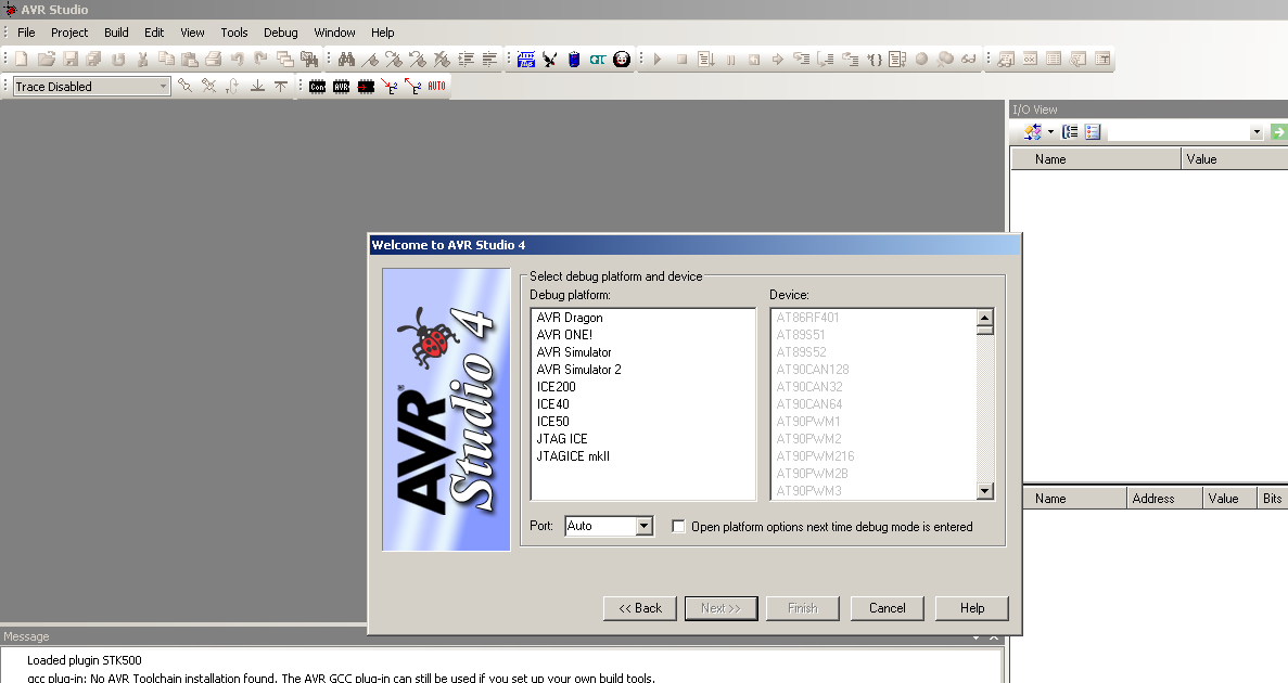
Startbildschirm der Software AVR Studio 4
AVR Studio File Project Build Edit View Tools Debug Window Help Trace Disabled I/O View Name Value Welcome to AVR Studio 4 Select debug platform and device Debug platform: Device: AVR Dragon AT86RF401 AVR ONE! AT89S51 AVR Simulator AT89S52 AVR Simulator 2 AT90CAN128 ICE200 AT90CAN32 ICE40 AT90CAN64 ICE50 JTAG ICE AT90PWM1 JTAGICE mkII AT90PWM216 AT90PWM28 AT90PWM3 Port: Auto Open platform options next time debug mode
in „AT89S52 mit AVRisp MKII auslesen / flashen“ · Mikrocontroller und Digitale Elektronik · · Screenshots
-
Datei
main.c
"com74hc595.h" #include "R_TRIG.c" #include "config.h" #include "usart.h" #include "networkcard/enc28j60.h" #include "stack.h" #include "timer.h" #include "cmd.h" #include <stdint.h> #include <stdlib.h> #include <stdio.h> #include <stdbool.h> #include <avr/io.h> #include <avr/eeprom.h> #include <avr/pgmspace.h> #include <util/delay.h> #include <avr/interrupt.h> #include <string.h> #include "main.h" #if USE_ADC #include "analog.h" #endif #if USE_HTTPD #include "httpd.h" #include "base64.h" #endif #if USE_WOL #include "wol.h" #endif #if USE_TELNETD
in „Verzögerung Zündung TRIAC für Phasenanschnitt“ · Mikrocontroller und Digitale Elektronik ·
-
Datei
Konsolenausgabe.txt
avr/lib/avr5/atmega32u6 avr/lib/avr5/atmega406 avr/lib/avr5/atmega644rfr2 avr/lib/avr5/atmega64rfr2 avr/lib/avr5/atmega64 avr/lib/avr5/atmega64a avr/lib/avr5/atmega640 avr/lib/avr5/atmega644 avr/lib/avr5
in „cannot read spec file 'device-specs/specs-atmega4808'“ · Mikrocontroller und Digitale Elektronik ·
-
Datei
test.lst
unsigned char data) { while (EECR & (1<<EEPE)); // warten bis Zugriff m glich 22: e1 99 sbic 0x1c, 1 ; 28 24: fe cf rjmp .-4 ; 0x22 <Write_EE> EEARL = adr; 26: 8e bb out 0x1e, r24 ; 30 EEDR = data; 28: 6d bb out 0x1d, r22 ; 29 EECR |= (1<<EEMPE); // Write vorbereiten 2a: e2 9a sbi 0x1c, 2 ; 28 EECR |= (1
in „EEPROM Schreibfrequenz auf eine Adresse“ · Mikrocontroller und Digitale Elektronik ·
-
Datei
UART.h
/* * UART.h * * Created on: Feb 28, 2011 * Author: toti */ #ifndef UART_H_ #define UART_H_ #include <avr/io.h> #include "regs.h" #include <util/delay.h> #include <avr/interrupt.h> #define XON 17 #define XOFF 19 #define FOSC 8000000 // Clock Speed #define BAUD 9600 #define MYUBRR FOSC/16/BAUD-1 #define UART_RX_BUFFER_SIZE 64 #define UART_RX_BUFFER_MASK (UART_RX_BUFFER_SIZE - 1) #define UART_TX_BUFFER_SIZE 64 #define UART_TX_BUFFER_MASK (UART_TX_BUFFER_SIZE - 1) /* ** high byte error return code of uart_getc() */ #define
in „UART Software Flow Control Befehle werden ignoriert“ · Mikrocontroller und Digitale Elektronik ·
-
Datei
Programm_Option_-v_Ausgabe_.txt
/bin/avr-g++ Target: avr Configured with: ../../downloads/gcc/configure --prefix=/home/ubuntixer/local/avrWindows64/ --target=avr --disable-nls --host=x86_64-w64-mingw32 --build=x86_64-linux-gnu --enable-languages
in „GCC v14 Release“ · Mikrocontroller und Digitale Elektronik ·
-
Datei
Programm_Option_-v_und_-Wl-v_Ausgabe_.txt
/bin/avr-g++ Target: avr Configured with: ../../downloads/gcc/configure --prefix=/home/ubuntixer/local/avrWindows64/ --target=avr --disable-nls --host=x86_64-w64-mingw32 --build=x86_64-linux-gnu --enable-languages
in „GCC v14 Release“ · Mikrocontroller und Digitale Elektronik ·
-
Datei
log.txt
Bitno Value ----------- -------- -------- ----- ----- READ 31 VALUE 7 1 30 VALUE 6 0 29 VALUE 5 1 28 VALUE 4 0 27 VALUE 3 0 26 VALUE 2 0 25 VALUE 1 0 24 VALUE 0 0 23 VALUE 7 0 22 VALUE 6 0 21 IGNORE 5 0 20 IGNORE 4 0 19 IGNORE 3 0 18 IGNORE 2 0 17 IGNORE 1 0 16 ADDRESS 8 0 15 ADDRESS 7 0 14 ADDRESS
in „USBasp + AVSDUDE + ATmega8 Problem“ · Mikrocontroller und Digitale Elektronik ·
-
Datei
Eclipse.txt
00000026 <main>: TWI_Master_t twiMaster; /*!< TWI master module. */ int main(void) { 26: df 93 push r29 28: cf 93 push r28 2a: cd b7 in r28, 0x3d ; 61 2c: de b7 in r29, 0x3e ; 62 2e: 2a 97 sbiw r28, 0x0a ; 10 30: cd bf out 0x3d, r28 ; 61 32: de bf out 0x3e, r29 ; 62 /*! Buffer with test data to send.*/ uint8
in „XMega Eclipse, AVR-Studio Interrupt Unterschiede“ · Mikrocontroller und Digitale Elektronik ·
-
Datei
rf22.c
Funkmodule ------------------------------------------------------------------------------*/ #include <avr/io.h> #include <avr/interrupt.h> #include <avr/pgmspace.h> #include "rf22.h" #include "usart.h" //####################################################################################################
in „RFM22B Beispiel Projekt gesucht.“ · Mikrocontroller und Digitale Elektronik ·
-
Datei
gcc9.2_binutils2.34_Konsolenausgabe.txt
avr/lib/avr5/atmega32u6 avr/lib/avr5/atmega406 avr/lib/avr5/atmega644rfr2 avr/lib/avr5/atmega64rfr2 avr/lib/avr5/atmega64 avr/lib/avr5/atmega64a avr/lib/avr5/atmega640 avr/lib/avr5/atmega644 avr/lib/avr5
in „Toochain bauen avr-gcc-x.x mit binutils-2.34 funktioniert nicht“ · Mikrocontroller und Digitale Elektronik ·
-
Datei
can_sd.c
define OSCSPEED 16000000 /* in Hz */ #define CAN_BAUDRATE 1000 //Für 500kBits/s Baudrate #include <avr/io.h> #include "can.h" #include <avr/interrupt.h> #include "ff.h" #include "diskio.h" #define nop() asm("NOP") typedef uint8_t U8; typedef uint16_t U16; typedef uint32_t U32; typedef uint64_t U64; typedef int8_t S8; typedef int16_t S16; typedef int32_t S32; typedef int64_t S64; U8 data[2048]; BYTE test = 0; int pins; ISR(BADISR_vect) {set_leds(1);} ISR(INT0_vect) {set_leds(2);} ISR(INT1_vect) {set_leds(3);} ISR(INT2_vect) {set_leds(4);} ISR(INT3_vect) {set_leds(5);}
in „ISR(SPI_STC_vect) wird nicht verlassen“ · Mikrocontroller und Digitale Elektronik ·
-
Datei
HW-PWM_an_3_Pins.c
0x96, 0x93, 0x90, 0x8C, 0x89, 0x86, 0x83, 0x80, 0x7D, 0x7A, 0x77, 0x74, 0x70, 0x6D, 0x6A, 0x67, 0x64, 0x61, 0x5E, 0x5B, 0x58, 0x55, 0x52, 0x4F, 0x4D, 0x4A, 0x47, 0x44, 0x41, 0x3F, 0x3C, 0x39, 0x37, 0x34, 0x32, 0x2F, 0x2D, 0x2B, 0x28, 0x26, 0x24, 0x22, 0x20, 0x1E, 0x1C, 0x1A, 0x18, 0x16, 0x15, 0x13,
in „Umschalten von 3 HW-PWM Kanälen beim ATMEGA8515“ · Mikrocontroller und Digitale Elektronik ·