/* Generic ESP8266 Modul sketch_MAIN8266.ino aus BasicHTTPClient.ino Created on: 27.03.2024 liest den Status aus Shelly 3EM, filtert nach "POWER",ermittelt den Strom eines Moduls, schaltet die notwendige/zulässige Anzahl Module zu oder ab, und
/* Generic ESP8266 Modul sketch_MAIN8266.ino aus BasicHTTPClient.ino Created on: 27.03.2024 liest den Status aus Shelly 3EM, filtert nach "POWER",ermittelt den Strom eines Moduls, schaltet die notwendige/zulässige Anzahl Module zu oder ab, und
gesamte Steuerung der Gärbox in die 275 Zeilen zu packen, die bisher in der defaults_user_settings.ino allein die Verwaltung und Speicherung der Produkteinstellungen braucht. > Was man auf jeden Fall noch einbauen sollte: > Nicht immer an die gleiche Stelle im EEprom speichern. Im Besonderen, wenn
Angefangen mit dem Sketch-Ordner selbst sieht das dann so aus: [c] .../sketches/my-sketch/my-sketch.ino .../sketches/my-sketch/libraries/my-function/my-function.h [/c] Der Kompiler scheint die Datei so nicht zu finden. Entweder mach ich auf meinem Rechner was verkehrt in den Namen oder ist etwas
, besser ist allerdings das [c] Tag für C/Cpp. Und noch besser den Code als Anhang mit der Endung .ino oder .cpp anhängen. Wünsche weiterhin maximale Erfolge.
/* Description: This program evaluates the pulse length of an oscillator, whose frequency is determined by a coil with a movable ferrite core. The movable ferrite core simulates the bolt of a lock, which enters a sensor coil - that means: the whole circuit works as an inductive proximity sensor, detecting the lock-state of a lock (unlocked/intermediate/locked): The result is displayed on an OLED-display as well as on an LED string (similar to a traffic light. A calibration button hooked to the nano can be used to calibrate min/max values of the osczillator's pulse length. The whole project (including
hast dieses "Bios". Wenn Du das aktuelle (auch letzte) "Bios" benutzt (S220718-R290823_IOS-Z80-MBC2.ino), findest Du ab line 892 die Definition der IO-Operationen, die vom ATMEGA ausgefuehrt werden. Ab line 974 findest Du den Zugriff auf den MCP27016: [c] Wire.beginTransmission(GPIOEXP_ADDR); Wire.write
Routinen loadByteToRAM(byte value) und loadHL(word value) statt (line 2506ff in S220718-R290823_IOS.MBC2.ino): [c] void loadByteToRAM(byte value) // Load a given byte to RAM using a sequence of two Z80 instructions forced on the data bus. // The RAM_CE2 signal is used to force the RAM in HiZ, so the
://github.com/mobizt/ESP-Mail-Client/blob/master/examples/IMAP/Read_Single_Email/Read_Single_Email.ino Hier würde ich (ganz unten) msg.subject und ggf. msg.text.content parsen, um die nötigen Infos zu erhalten. Eventuell auch msg.date und msg.sender zur Validierung. Es gibt auch kleine Statusdisplays
Kosenamen und liebevoll, aber auch scherzhaft oder ironisch. Die typischen Endungen lauten -ina und -ino, oder -etta und -etto; und zuweilen auch -ella und -ello." https://de.m.wikipedia.org/wiki/Diminutiv#Italienisch
der Arduino-IDE ja mal ein Beispiel reinladen und das für den Arduino Uno kompilieren. Das TTN-OTAA.ino-Beispielprogramm braucht etwa 24K Speicher und 1.4K RAM, allzu viel bleibt da also nicht mehr für Eigenes übrig, aber wenn man gut programmiert, reicht es durchaus für einen Sensor. Nur: Moderne
github.com/witnessmenow/ESP32-Cheap-Yellow-Display/blob/main/Examples/Basics/1-HelloWorld/1-HelloWorld.ino neu geflasht, aber es bleibt dunkel. Weiß jemand, woran das liegt?
/* Generic ESP8266 Modul sketch_mar27c.ino aus BasicHTTPClient.ino Created on: 27.03.2024 liest den Status aus Shelly 3EM, filtert nach "POWER",ermittelt den Strom eines Moduls, schaltet die notwendige/zulässige Anzahl Module zu oder ab, und
Modellbahn_TestEncoderInterfacePCF8575_PCA9685_FRAM_016\Modellbahn_TestEncoderInterfacePCF8575_PCA9685_FRAM_016.ino C:\Arduino IDE Portable\AVRxDB\arduino-1.8.19\arduino-builder -compile -logger=machine -hardware C:\Arduino IDE Portable\AVRxDB\arduino-1.8.19\hardware -hardware C:\Arduino IDE Portable\AVRxDB\arduino
Local\\Temp\\arduino_build_164294\\sketch\\Modellbahn_TestEncoderInterfacePCF8575_PCA9685_FRAM_016.ino.cpp" -o "C:\\Users\\Worker\\AppData\\Local\\Temp\\arduino_build_164294\\sketch\\Modellbahn_TestEncoderInterfacePCF8575_PCA9685_FRAM_016.ino.cpp.o" In file included from C:\Arduino IDE Portable\AVRxDB
Modellbahn_TestEncoderInterfacePCF8575_PCA9685_FRAM_016\Modellbahn_TestEncoderInterfacePCF8575_PCA9685_FRAM_016.ino C:\Arduino IDE Portable\AVRxDB\arduino-1.8.19\arduino-builder -compile -logger=machine -hardware C:\Arduino IDE Portable\AVRxDB\arduino-1.8.19\hardware -hardware C:\Arduino IDE Portable\AVRxDB\arduino
[c] /* Generic ESP8266 Modul sketch_mar27c.ino aus BasicHTTPClient.ino Created on: 27.03.2024 liest den Status aus Shelly 3EM, filtert nach "POWER",ermittelt den Strom eines Moduls, schaltet die notwendige/zulässige Anzahl Module zu oder ab, und
in several sub-branches in order to 1 2 talk to one device at a time • It is programmable through Ino additional pins are required for control I C MULTIPLEXER • More than one multiplexer can be plugged in the same I MASTER The multiplexer allows to address 1 device • Products then the other one # of
Das heißt wenn es im Datenblatt 0x68 sein muss ich in meinem INO Coder die 0x69 als Adresse angeben? Mit der 0x69 kann ich zumindest den MPU6050 auslesen. Mit der 68 nicht.
Jurgen H. schrieb im Beitrag #7657881: > Das heißt wenn es im Datenblatt 0x68 sein muss ich in meinem INO Coder > die 0x69 als Adresse angeben? Mit der 0x69 kann ich zumindest den > MPU6050 auslesen. Mit der 68 nicht. Nun Das ist doch offensichtlich oder? wenn das Ding auf 69 antwortet hast du eine
/////////////////////////////////////////////////////// // // DCC packet analyze: Ruud Boer, October 2015 // DCC packet capture: Robin McKay, March 2014 // ------------------------------------------------------- // Version 2.0: Jürgen Winkler, March 2016 // - improve accessory decoder packet handling // - improve detection of repeated = same packets // - corrected display of on/off for basic accessory decoder packets // - add hexdecimal output format for packets // - packet output format may be selected using keyboard commands (bin,hex,both,none) // - display of idle packet may be toggled using
//------------------------------------------------------------------------------------------------------- /* DCC-Monitor zur Ausgabe der DCC-Befehle auf dem seriellen Monitor ================================================================= V 1.4, 17.12.2020 domapi NEU 17.12.2020 - Anpassung der Pufferroutine bei Schaltartikel-Befehlen (Acc), da bei DCC++ teilweise kein "Signal aus"-Befehl gesendet wird. Die Folge war, dass Befehle verschluckt wurden. - Performance optimiert: 3 x break eingebaut in Puffer-Löschroutine. NEU 12.12.2020 - Der ESU-Lokprogrammer sendet offensichtlich zusätzliche DCC-Kommandos
arduino/tools/bossac/1.9.1-arduino5/bossac -d --port=ttyACM0 -U -e -w /tmp/arduino_build_695814/Blink.ino.bin -R Set binary mode Send auto-baud Set binary mode Beim Hochladen des Sketches ist ein Fehler aufgetreten No device found on ttyACM0 [/code] ... und der (erwarteten Fehlermeldung) auf der
Nullen, wie der String Buchstaben hat. [c] /* Generic ESP8266 Modul aus BasicHTTPClient.ino Created on: 27.03.2024 liest den Status aus Shelly 3EM, filtert nach "POWER",ermittelt den Strom eines Moduls, schaltet die notwendige/zulässige Anzahl Module zu oder ab, und funkt das
//MQTT Broker with DoorbellButton input at IO4 and OTA //For the first time you must program via COMx: //Afterwards you can chage the program port to the network adress wich //is reported at line 38 to the serial monitor #include <Arduino.h> #include <PicoMQTT.h> #include <WiFi.h> #include <HTTPClient.h> //OTA Includes and definitions ############################ #include <ArduinoOTA.h> const char* ssid = "SSID"; const char* password = "PASSWORD"; //OTA ##################################################### PicoMQTT::Server mqtt; unsigned long timeout = millis(); int greeting_number = 1; const int
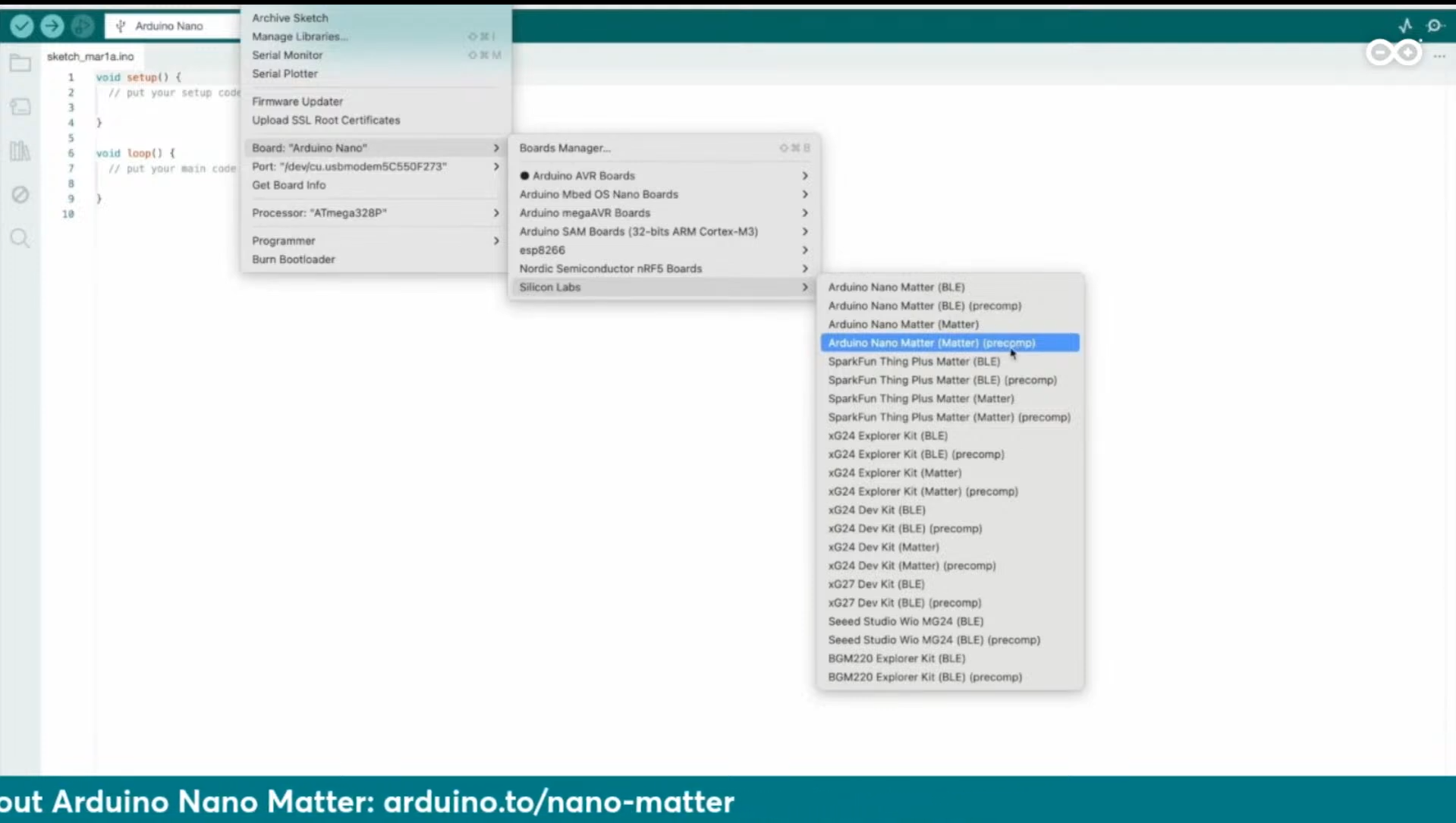
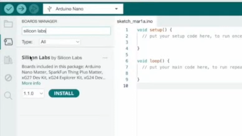
Thing Plus Matter, xG27 Dev Kit, xG24 Explorer Kit, xG24 Dev... More info 1.1.0 INSTALL sketch_mar1a.ino void setup() { // put your setup code here, to run once void loop() { // put your main code here, to run repeat
simuliert? Da ich mich lernmäßig durch diverse Beispiele durchwuseln muss, greife ich gern auf Arduino-ino's zu, um Bibliotheken für PICs zu verwenden oder anzupassen.Dazu schien mir ein Simulator für schnellere Wechsel und Proben diverser Controller vorerst ebenfalls sinnvoll,da ich mir keine zich Messgeräte
Das geht ja schon gut los. Threat --> Gefahr Rudi R. schrieb im Beitrag #7630099: > Arduino-ino's Bitte keine Deppenapostrophen! http://www.deppenapostroph.info Rudi R. schrieb im Beitrag #7630099: > um Bibliotheken für PICs zu verwenden oder anzupassen Also paar Bibliotheken zusammenklöppeln
kommen. Um das zu beforschen, spielst Du aus der "XPT2046_Touchscreen-1.4.0.zip" die "TouchTest.ino" auf und stocherst nicht in Deinem 1900-Zeilen Komplettprogramm herum. Im Komplettprogramm gibt es 9 Abfragen "ts.getPoint();", z.B. Zeilen 627/628, da mal testweise x gegen y tauschen?
Bei der Bibliothek XPT2046 gibt es die Beispielprogramme TouchTest.ino und TouchTestIRQ.ino Benutze das um die min/max Koordinaten für _deinen_ Touchscreen zu bestimmen. Das sind resistive Touch mit viel Toleranzen. Außerdem bedient man den Touch am besten mit dem mitgelieferten
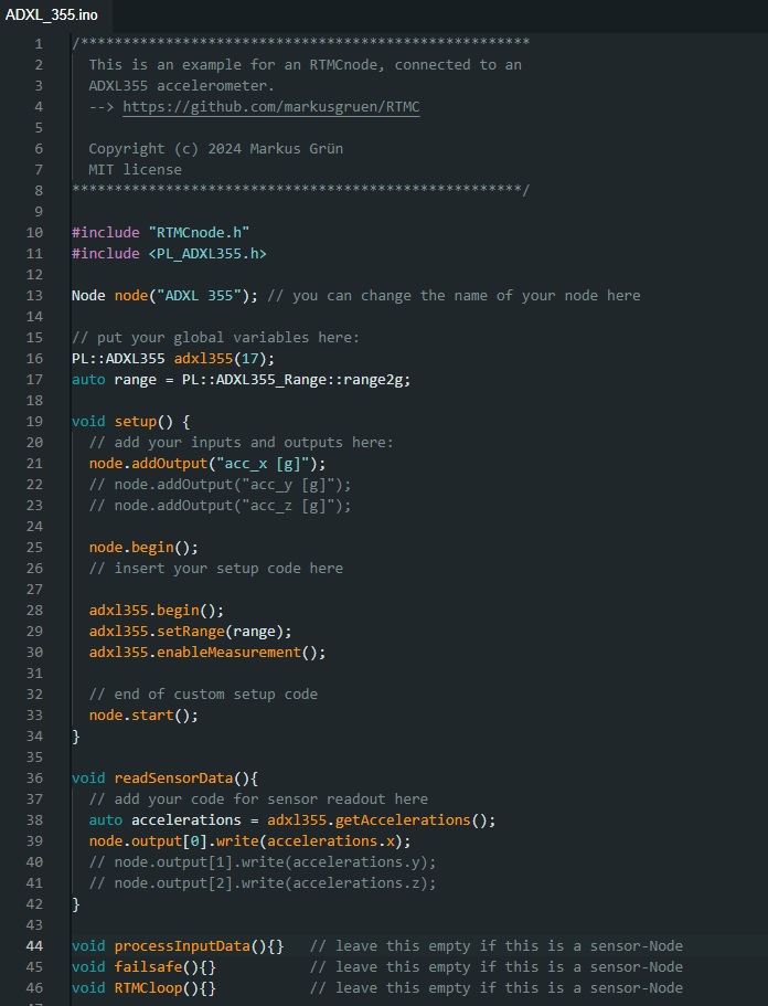
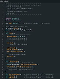
ADXL_355.ino
// ****************************************************
// This is an example for an RTMCnode, connected to an
// ADXL355 accelerometer.
// --> https://github.com/markusgruen/RTMC
// Copyright (c) 2024
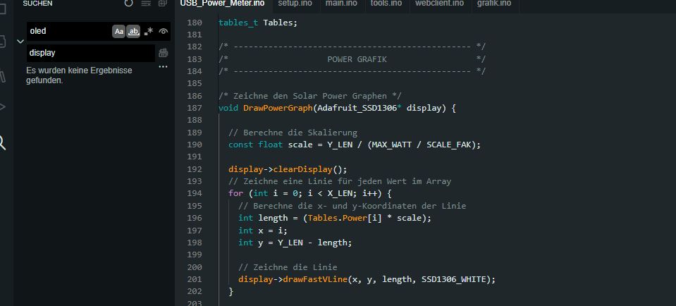
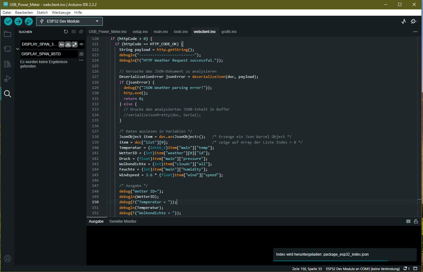
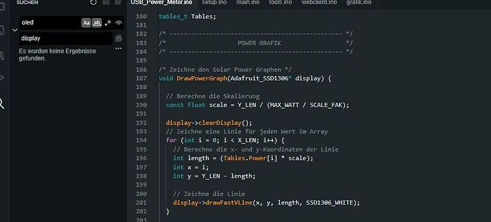
USB_Power_Meter.ino setup.ino main.ino tools.ino webclient.ino grafik.ino
oled
display
Es wurden keine Ergebnisse gefunden.
tables_t Tables;
/*
/*
POWER GRAFIK
/*
*/
/* Zeichne den Solar Power Graphen */
void DrawPowerGraph
/************************************************************************** This is an example for our Monochrome OLEDs based on SSD1306 drivers Pick one up today in the adafruit shop! ------> http://www.adafruit.com/category/63_98 This example is for a 128x32 pixel display using I2C to communicate 3 pins are required to interface (two I2C and one reset). Adafruit invests time and resources providing this open source code, please support Adafruit and open-source hardware by purchasing products from Adafruit! Written by Limor Fried/Ladyada for Adafruit Industries, with contributions from the open
Wenn man das void durch int ersetzt kommt neuer Murks. E:\Embedded\ESP32\USB_Power_Meter\grafik.ino:107:21: error: variable or field 'DrawPowerGraph' declared void void DrawPowerGraph(Adafruit_SSD1306* oled) { ^~~~~~~~~~~~~~~~ E:\Embedded\ESP32\USB_Power_Meter\grafik.ino:107
\ESP32\USB_Power_Meter\grafik.ino:107:39: error: 'oled' was not declared in this scope void DrawPowerGraph(Adafruit_SSD1306* oled) { ^~~~
#include "Wire.h" #include "LiquidCrystal_I2C.h" // (1) LiquidCrystal_I2C LCD(39, 20, 4); // Adress, Row, Col /* Adress-Table Adress A0 A1 A2 32 L L L 33 H L L 34 L H L 35 H H L 36 L L H 37 H L H 38 L H H 39 H H H <- default */ void setup() { LCD.init(); LCD.backlight(); } void loop() { LCD.clear(); char cstr[8] = "1. Zeile"; LCD.setCursor(0, 0); LCD.print(cstr); cstr[0] = '2'; LCD.setCursor(0, 1); LCD.print(cstr); cstr[0] = '3'; LCD.setCursor(0, 2); LCD.print(cstr); cstr[0] = '4'; LCD.setCursor(0, 3); LCD.print(cstr); delay(2000); LCD.clear(); }
#include "Wire.h" #include "LiquidCrystal_I2C.h" // (1) LiquidCrystal_I2C LCD(39, 20, 4); // Adress, Row, Col /* Adress-Table Adress A0 A1 A2 32 L L L 33 H L L 34 L H L 35 H H L 36 L L H 37 H L H 38 L H H 39 H H H <- default */ void setup() { LCD.init(); LCD.backlight(); } void loop() { LCD.clear(); char cstr[8] = "1. Zeile"; LCD.setCursor(0, 0); LCD.print(cstr); cstr[0] = '2'; LCD.setCursor(0, 1); LCD.print(cstr); cstr[0] = '3'; LCD.setCursor(0, 2); LCD.print(cstr); cstr[0] = '4'; LCD.setCursor(0, 3); LCD.print(cstr); delay(2000); LCD.clear(); }
// |———————————————————————————————————————————————————————| // | made by Arduino_uno_guy 11/13/2019 | // | https://create.arduino.cc/projecthub/arduino_uno_guy| // |———————————————————————————————————————————————————————| #include LiquidCrystal_I2C.h #include Wire.h //initialize the liquid crystal library //the first parameter is the I2C address //the second parameter is how many rows are on your screen //the third parameter is how many columns are on your screen LiquidCrystal_I2C lcd(0x27, 16, 2); void setup() { //initialize lcd screen lcd.init(); // turn on the backlight lcd.backlight(); }
das hier https://github.com/esp8266/Arduino/blob/master/libraries/ESP8266WiFi/examples/IPv6/IPv6.ino keine v6-IP liefert. Ich habe das jetzt mit unterschiedlichen Routern/WLANs versucht. WLAN/v4 geht - aber v6 geht nicht: (IP unset) resolving www.google.com: 142.250.185.228 resolving

 Bild
Bild
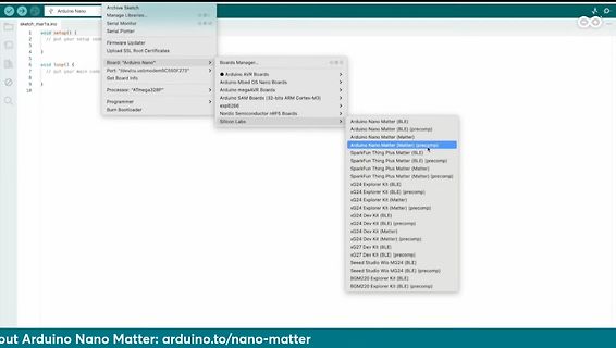
 Bild
Bild
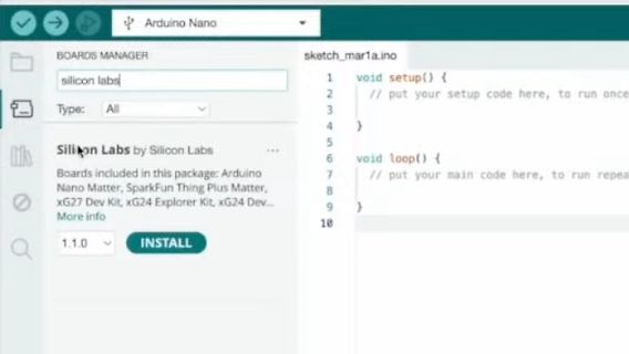
 Bild
Bild
 Bild
Bild
 Bild
Bild
 Bild
Bild