Hand. Ach so, vielleicht nochmal einen Link auf das Zeug: https://www.amazon.de/dp/B0BHNRY2WD?ref=ppx_yo2ov_dt_b_fed_asin_title Finde ich sogar erstaunlich preiswert! Vanye
andere Richtung Ableitfähigkeit/ESD. Mit freundlichem Gruß: Bernd Wiebus alias dl1eic http://www.l02.de
4.6. Crystal Oscillator Parameter Symbol Test Condition Min Typ Max Unit Crystal Frequency fXTAL 0.02 — 30 MHz 4.1.7 External Clock Input Table 4.7. External Clock Input Parameter Symbol Test Condition Min Typ Max Unit External Input CMOS Clock fCMOS 0 — 48 MHz Frequency (at EXTCLK pin) silabs.com |
accompany this product. They contain important information on setting up and using the device. You should refer to these instructions, even if you are buying this product for someone else. Please retain these Operating Instructions for future use! A list of the contents can be found in the Table of contents,
Dambar shear- 0.70 mm 0.99 mm off area (max.) (0.028 in.) (0.039 in.) a. The preceding conditions refer to measurement with a thermocouple mounted at the bottom of the PCB. b. Use only bottom pre-heaters to reduce thermal stress NOTE: Refer to application note AN1027 for more experienced by LED. information on soldering LED components. Broadcom AV02-1552EN 7 HLMP-40xx, HLMP-08xx Data Sheet T-1 3/4, 2 mm x 5 mm Rectangular Bicolor LED Lamps Over-sizing the PTH can lead to twisted LED after clinching. On the other hand under sizing the PTH can cause
0V to 2.6V. When it is form the COMP voltage, which is used to lower than the internal reference (REF), SS control the power MOSFET current. overrides REF so the error amplifier uses SS as the reference. When SS is higher than REF, During operation, the minimum COMP voltage REF regains control. is clamped
1.10 MAX. H (0.043) F I 0.80 MIN. G (0.031) J 0.60 MIN. (0.024) Dimension CD0603-B0xR 2.30 K (0.091)REF. 1.6 ± 0.10 A (0.063 ± 0.004) DIMENSIONS: MM B 0.9 ± 0.10 (INCHES) (0.035 ± 0.004) C 0.7 ± 0.10 Physical Specifications (0.028 ± 0.004) 0.20P. Encapsulation.............................Molded plastic
recover. FAN ON/OFF CONTROL RTH3≧50℃ FAN ON, ≦40℃ FAN OFF FUNCTION (Typ.) WORKING TEMP. -25 ~ +70℃ (Refer to "Derating Curve") WORKING HUMIDITY 20 ~ 90% RH non-condensing ENVIRONMENTTORAGETEMP.,HUMIDITY -40 ~ +85℃, 10 ~ 95% RH TEMP. COEFFICIENT ±0.03%/℃ (0 ~ 50℃) VIBRATION 10 ~ 500Hz, 5G 10min./1cycle,
Messungen sehr viel bessere Eigenschaften. Bzgl. was? Rauschen? Temperaturdrift? Belastbarkeit von V_ref? Linearität? Ansonsten: Nette Idee :)
Temperaturdrift? Siehe: https://www.mikrocontroller.net/topic/530150#new > Belastbarkeit von V_ref? Linearität? Da unterscheiden die sich nicht wesentlich. > Ansonsten: Nette Idee :) Danke!
for working as wakeup sources when the chip is working in the low-power modes (for details, please refer to Section.4.3), or can be used as regular GPIOs (for details, please refer to Chapter 5 IO MUX and GPIO Matrix (GPIO, IO MUX)). • RTC fast memory: 8 KB SRAM that works under CPU clock (CPU_CLK), which
) 132-pin PQFP (104) tPD (ns) 10 10 tCO (ns) 6 6 fCNT (MHz) 80 80 Altera Corporation 265 A-DS-FLSH-02 FLASHlogic Programmable Logic Device Family Data Sheet ... and More LABs can be configured as either one of the following: – 24V10 logic block with 10 macrocells Features – 128 10 SRAM block 3.3-V or
Table 6. Timer 2 as a Counter MODE TMOD INTERNAL CONTROL (Note 1) EXTERNAL CONTROL (Note 2) 16-bit 02H 0AH Auto-Reload 03H 0BH NOTES: 1. Capture/reload occurs only on timer/counter overflow. 2. Capture/reload occurs on timer/counter overflow and a 1-to-0 transition on T2EX (P1.1) pin except when Timer
0.9 V 1mA < I SET≤ 5mA 1.0 1.0 V + Average Change in Set Current 2μA ≤ I SET ≤ 1mA 1.5 ≤ V ≤ 5V 0.02 0.05 0.02 0.1 %/V with Input Voltage 5V ≤ V ≤ 40V 0.01 0.03 0.01 0.05 %/V 1mA < I SET≤ 5mA 1.5V ≤ V ≤ 5V 0.03 0.03 %/V 5V ≤ V ≤ 40V 0.02 0.02 %/V Temperature(3)pendence of 25μA ≤ ISET ≤ 1mA 0.96T T 1.04T
einen Spannungsabfall von 1O mV/K verursachen. C 5 unterdrückt durch das Kabel aufgefangene 0 tcz t REF-02 H F-Störungen. Der Sensor TEMJ TRIM wird aus einem 9-V-Block ver- §' sorgt.Die Spannungsdifferenz rc wird direktan Klernme M + N gegen Masse abgegriffen.Hier Q,,u., empf iehltsich ein DVM mit -l
TO interessiert, blättere ich mal die 100 Zeitschriften durch. PS: Habe es gefunden. Nicht REF200 sondern REF02. Ist aus Elektor7-8 1991. Ich stelle das mal hier rein. Ich hoffe kriege keinen ärger. Obwohl 1991...
Datenblatt wird das auch beschrieben. PS: Das teuerste ist allerdings die Spannungsreferenz. Der REF02 kostet schon mal 12Euro.
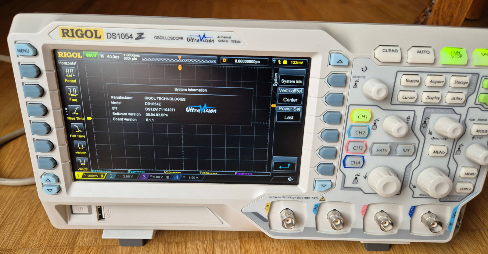
Information Manufacturer RIGOL TECHNOLOGIES Model DS1054Z SN 01ZA171104971 Software Version 00.04.02.SP4 Board Version 0.1.1 UltraVision System Info Vertical Ref Center Power Set Last CH1 CH2 CH3 CH4 MATH REF MENU MODE POSITION LEVEL HORIZONTAL Auto Normal Display Utility Acquire Storage All Inputs
the LCD first, and then apply VGH. Note 2: DVDD setting should match the signals output voltage (refer to Note 3) of customer’s system board. Note 3: DCLK, HS, VS, RESET, U/D, L/R, DE, R0~R7, G0~G7, B0~B7, MODE, DITHB. Note 4: Typical VCOM is only a reference value. It must be optimized according to
the LCD first, and then apply VGH. Note 2: DVDD setting should match the signals output voltage (refer to Note 3) of customer’s system board. Note 3: DCLK, HS, VS, RESET, U/D, L/R, DE, R0~R7, G0~G7, B0~B7, MODE, DITHB. Note 4: Typical VCOM is only a reference value. It must be optimized according to
S102S02 Series S202S02 Series T (rms)≤8A, Zero Cross type S102S02 Series SIP 4pin Triac output SSR S202S02 Series ∗Non-zero cross type is also available. (S102S01 Series/ S202S01 Series) ■ Description ■ Agency approvals/Compliance S102S02 Series and S202S02 Series Solid State 1. Recognized by UL508, file No. E94758 (as models No. Relays (SSR) are an integration of an infrared emitting S102S02/S202S02) diode (IRED), a Phototriac Detector
überladen. Ich hab schon lange kein C++ mehr gemacht, irgend was in die richtung: [code] class BitRef { private: const int bit; unsigned char*const byte; public: BitRef(unsigned char* b, int i) : byte(b), bit(i) { } operator bool() const { return *this->byte & (1<<this->bit);
Diode 0001 1011: Continuity 0000 0011: Squarewave 0001 1101: Resistance Exponent Volt DC: 0000 0010: 0x02, mV DC [000.0] E-1 0000 0100: 0x04 V DC [0.000] E-3, schreibt man 1234 wird 1.234V angezeigt 0000 1000: V DC [00.00] E-2 0001 0000: V DC [000.0] E-1 0010 0000: V DC [0000.] E-0 */ #define IDX_MODUS 3
NU_VALID_HEADER(7:0). 63 Language support for thai. 49 - 52 Text detection and WSS reception improvement (refer chapters 1.8 and 1.9). 52 - 53 Additional information about the CVBS signal quality. 53 Firmware refresh for the external DRAM up to 16 Mbit. 4 Appl. 57 Bits 47…40 must be defined new Notes The layout
4.6. Crystal Oscillator Parameter Symbol Test Condition Min Typ Max Unit Crystal Frequency fXTAL 0.02 — 30 MHz 4.1.7 External Clock Input Table 4.7. External Clock Input Parameter Symbol Test Condition Min Typ Max Unit External Input CMOS Clock fCMOS 0 — 48 MHz Frequency (at EXTCLK pin) silabs.com |
pF (3) SCL VI= V CCor GND , Switch OFF 20 28 (1) For operation between specified voltage ranges, refer to the worst-case parameter in both applicable ranges. (2) All typical values are at nominal supply voltage (1.8-, 2.5-, 3.3CC), A = 25°C. (3) RESET = V CC (held high) when all other input voltagIs
Tel: (310) 252-7105 TAC Fax: (310) 252-7903 Visit us at www.irf.com for sales contact information.02/04 8 www.irf.com Note: For the most current drawings please refer to the IR website at: http://www.irf.com/package/ IMPORTANT NOTICE The information given in this document shall in no For further information
R e 0.04 n 0.20 r O o c - u t S i Id = 4.0A o r 0.03 n D a 0.10 ,) D VGS = 4.5V n , ( n D o R S 0.02 D 0.00 R 2.0 2.5 3.0 3.5 4.0 4.5 5.0 5.5 6.0 6.5 7.0 0 10 20 30 40 V Gate -to -Source Voltage ( V ) GS, iD , Drain Current ( A ) Fig 11. On-Resistance Vs. Gate Voltage Fig 12. On-Resistance Vs. Drain
Datentypen wie z.B. IEEE 1164 std_logic gebräuchlich. Grad mal https://www.hdlworks.com/hdl_corner/vhdl_ref/VHDLContents/StdLogic1164.htm nach [code] *ignor* [/code] ge-grept -> 0 matches.
und die Ausgänge high-aktiv, genügt ein einfaches RS-Flipflop aus zwei NOR-Gattern. Mit einem 74xx02 kann man diese Schaltung sogar zweimal realisieren.
and added it to the > datasheet." > https://forum.buspirate.com/t/rp2350-bus-pirate-5xl-and-6/529?ref=buspirate.com Naja, "freaks me out" ist nicht gerade eine klare Beschreibung eines Fehlerbildes. Unklar bleibt ebenfalls, ob jetzt der Logicanalyzer nicht funktioniert, weil da ein Pico 2 tut,
keinen Strom an, die Anzeige springt höchstens mal von den 0,01µA die es ohne Strom anzeigt auf 0,02µA. Bauform B. schrieb im Beitrag #7729618: > In dem Zustand fließt wahrscheinlich kaum weniger Strom. I2C mit > vernünftigen Pull-Up sollte aber immer funktionieren. Und es ist ein > ganz anderes
Examples: Window Lift Drives Johnson Electric sales@johnsonelectric.com http://www.johnsonelectric.com 02PT001-101 Low Voltage DC Motors Outline Drawing: Johnson Electric sales@johnsonelectric.com http://www.johnsonelectric.com 02PT001-101 Low Voltage DC Motors Performance Curves: Units in Metric Johnson
folgende Komponenten gekauft und angeschlossen. Potentiometer: https://www.amazon.de/dp/B09YRDTRTV?ref=ppx_yo2ov_dt_b_fed_asin_title&th=1 TRU Components Drehzahl- und Leistungsregler: https://www.amazon.de/dp/B0767KKLKQ?ref=ppx_yo2ov_dt_b_fed_asin_title Rohrlüfter: https://www.ebay.de/itm/375090849208
Lothar M. schrieb im Beitrag #7727336: >> https://www.amazon.de/dp/B0767KKLKQ?ref=ppx_yo2ov_dt_b_fed_asin_title > Lies mal die Beschreibung dieses Moduls Welche Produktbeschreibung? Vielleicht habe ich Knöpfe vor den Augen, aber ich sehe dort nur dies: "TRU Components Drehzahl
Achse 0 SIGNAL SetIniPos :STD_LOGIC := '0';-- Iniposition setzen alle Achsen ----------------- SIGNAL REF00 :STD_LOGIC := '0';-- signal für REF Befehl 00 EBENE 0 SIGNAL REF01 :STD_LOGIC := '0';-- signal für REF Befehl 00 EBENE 1 SIGNAL REF02 :STD_LOGIC := '0';-- signal für REF Befehl 00 EBENE 2 --------
(08669) WO Kundendienst 6, TASTATUR-EINHEIT TE 3.51/355 6.1 &5ersicht ;r "3;: A Id.N8,r. 243 9615 02 1)~) TE 355 B Id.Nr. 241 964 01 4) 01 z)+) TE 355 D I< II 02 5) TE 355 A (1 II 02 4) TE 355 C w !, 03 5, TE 355 Id.Nr. 255 015 01 zj3)4, TE 355 B Id.Nr. 255 016 01 TE 355 A <I (1 02 3,4) 3j.t) TE 355 C " 9, 03 3,oi TE 355 D w 81 02 3,s) u- OÖö0 0000 000 0 00000 q oon @ ~0000. 0000 00000 00000 00000 GP 00000 00000 , hohe Ausführung breite Ausführung 1) ohne Grafiktasten 2) ohne Stecker X 1 (Anschluß Maschinenbedienfeld) 3) mit Masseanschluß
VCC AGND DGND VDD B0004-02 Submit Documentation Feedback 5 PCM1801 www.ti.com SBAS131C–OCTOBER 2000–REVISED JULY 2007 ANALOG FRONT-END (Single Channel) 1 F V IN 30 k 1 − + − 1 k (+) + + Delta-Sigma 1 k Modulator (−) V 1 REF 14 + 4.7 F V REF 4.7 F + V REF2 13 S0011-02 TYPICAL PERFORMANCE CURVES All specifications atAT = 25°C, VDD = VCC = 5 V, fS= 44.1 kHz, and SYSCLK = 384 f , uSless otherwise noted ANALOG DYNAMIC PERFORMANCE TOTAL HARMONIC
Richard hat eine eigene Abteilung dazu: https://www.richis-lab.de/REF00.htm
> KP303E, Ach Du Literpott ... Heiteck aus der Zone und vom Russen. https://www.richis-lab.de/REF18.htm https://www.richis-lab.de/REF15.htm https://www.shotech.de/media/products/KP303.pdf -------- Was ist eigentlich aus den ZTX312 geworden?
StarChips Technology SCT2932 V02_01; Nov/14 1.5A LED Driver with Internal Switch ProductDescription SCT2932 is a high efficiency, constant current, continuous mode inductive step-down converter, designed for driving constant current

 Bild
Bild
 Bild
Bild