-
Datei
uart.c
define UART1_CONTROL UCSR1B #define UART1_DATA UDR1 #define UART1_UDRIE UDRIE1 #elif defined(__AVR_ATmega64__) || defined(__AVR_ATmega128__) /* ATmega with two USART */ #define ATMEGA_USART0 #define ATMEGA_USART1 #define UART0_RECEIVE_INTERRUPT USART0_RX_vect #define UART1_RECEIVE_INTERRUPT USART1_RX_vect
in „AVR Bootloader in C - Artikel“ · Mikrocontroller und Digitale Elektronik ·
-
Datei
fixapfel.cpp
fixpointSub (fixpoint a, fixpoint b) { return a - b; } fixpoint fixpointMult (fixpoint a, fixpoint b) { int64_t r ; r = (int64_t ) a * (int64_t ) b ; // Das Zwischenergebnis kann bannig groß werden if ( r > (int64_t )( 2147483646.0 * fixpointEins ) ) { return 0x7FFFFFFFL ; // + Ueberlauf } if ( r < (int64_t
-
PDF
Dokumentation_MBHATM128-0206.pdf
nicht in Kinderhände. Verwendung und Betrieb: Ausgestattet mit dem programmierbaren Mikrocontroller ATmega128, kann es zur programmierbaren Ansteuerung/Regelung, in Verbindung mit elektrischen und elektronischen Baugruppen, die mit Kleinspannungen betrieben werden dienen. Für die direkte oder indirekte
in „atmega128 modul“ · Markt ·
-
Datei
timer0.c
bis 0 macht dann Interrupt //und CountMilliseconds wird um eins hochgezählt. Alle 1ms. Durch Teiler 64 und Zählerstand -115 //ergiebt sich dieser Wert. // //timer0.c //Angepasst für Atmega8 //Datum: 18.10.2008 //Version: 2.0 //Version: 2.1 30.12.2008 Zähler auf char geändert wegen Keyboard überlauf nach
in „If wird nicht ausgeführt“ · Mikrocontroller und Digitale Elektronik ·
-
Datei
output_build-console.txt
.elf "lcdHM1.eep" Finished building: lcdHM1.eep Invoking: Print Size avr-size --format=avr --mcu=atmega8 lcdHM1.elf pause(0); AVR Memory Usage ---------------- Device: atmega8 Program: 1976 bytes (24.1% Full) (.text + .data + .bootloader) Data: 634 bytes (61.9% Full) (.data + .bss + .noinit) Finished
in „missing ; behind __flash -> Was übersehe ich?“ · Mikrocontroller und Digitale Elektronik ·
-
Datei
baseTimerD.h
\Timer.h Timer0 * **************************************************************************** * ATmega48-88-168-328\Timer.h Timer1 * **************************************************************************** * ATmega-164-324-644-1284\Timer.h Timer0, Timer2(*) **************************************
in „Knoten im Kopf, Klassen und Vererbung“ · Mikrocontroller und Digitale Elektronik ·
-
 Bild
Bild
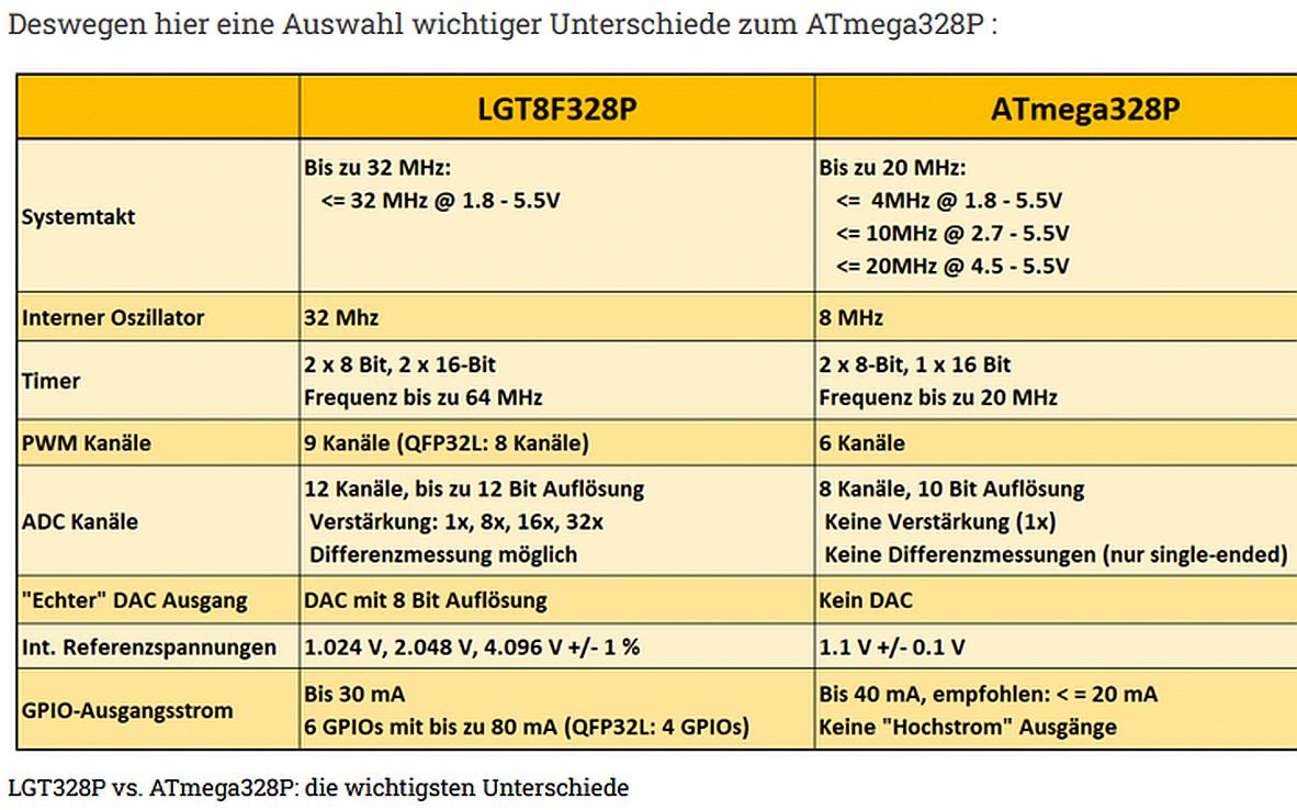
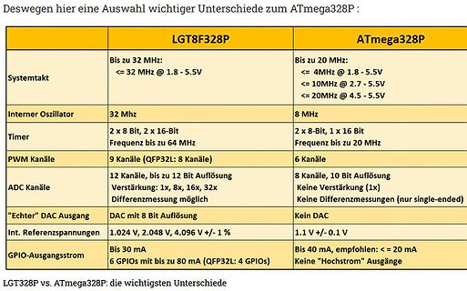
Vergleichstabelle LGT8F328P und ATmega328P
Deswegen hier eine Auswahl wichtiger Unterschiede zum ATmega328P: LGT8F328P | ATmega328P Systemtakt | Bis zu 32 MHz: <= 32 MHz @ 1.8 - 5.5V | Bis zu 20 MHz: <= 4MHz @ 1.8 - 5.5V, <= 10MHz @ 2.7 - 5.5V, <= 20MHz @ 4.5 - 5.5V Interner Oszillator | 32 Mhz | 8 MHz
in „Neue 8-Bit Tinys vorgestellt: 417/814/816/817“ · Mikrocontroller und Digitale Elektronik · · Diagramme
-
Datei
pegasus_5x7_font.bas
text screen with 15 x 7 characters using ' 5x7 Font. ' Display Controller Type: ST7626 ' Tested on ATMega8, 70% Flash used. Internal Oscillator 1 MHz. '############################################################### $crystal = 1000000 $regfile = "m8def.dat" $framesize = 10 Const Fontbreite = 5 '5x7Font
in „Mini-Farbdisplay (+mehr) für 1 Euro“ · Mikrocontroller und Digitale Elektronik ·
-
PDF
uC_Einfuehrung.pdf
zugänglich ist. Der Datenbus hingegen ist bei einigen Vertretern der AVR-Familie (nicht jedoch beim ATMega16) zugänglich und dementspre- chend ist es möglich, extern zusätzlichen Datenspeicher vorzusehen, dessen Größe lediglich durch den Adressraum des Controllers auf max. 64 KiB limitiert ist. Es ist zu
in „AVR Atmega16 Timer Problem“ · Mikrocontroller und Digitale Elektronik ·
-
Datei
Dokument2.txt
Direction Register #define on 1 #define off 0 // +++ Definition: USART Buffer #define USART0_R_BUFF_SIZE 64 // 2,4,8,16,32,64,128 or 256 bytes #define USART0_T_BUFF_SIZE 64 // 2,4,8,16,32,64,128 or 256 bytes #define USART0_R_BUFF_MASK (USART0_R_BUFF_SIZE - 1) #define USART0_T_BUFF_MASK (USART0_T_BUFF_SIZE
in „ATmega128 USART kriegs nicht zum Laufen / bin am verzweifeln“ · Mikrocontroller und Digitale Elektronik ·
-
Datei
Makefile-1.txt
assembler code only # # To rebuild project do "make clean" then "make all". # # MCU name #MCU = atmega32 MCU = atmega644 #MCU = atmega644p #MCU = atmega128 #Fuse settings for ATmega644 ifeq ($(MCU), atmega644) FUSE_BITS = -u -U lfuse:w:0xff:m -U hfuse:w:0xdf:m HEX_FILE_NAME = MEGA644 endif #Fuse settings for ATmega644P ifeq ($(MCU), atmega644p) FUSE_BITS = -u -U lfuse:w:0xff:m -U hfuse:w:0xdf:m HEX_FILE_NAME = MEGA644_P endif #Fuse settings for ATmega32 ifeq ($(MCU), atmega32) FUSE_BITS = -u -U lfuse:w:0xff:m
-
Datei
demo.c
AVR_AT90S8515__) || \ defined(__AVR_AT90S4434__) || defined(__AVR_AT90S8535__) || \ defined(__AVR_ATmega163__) # define OC1 PD5 # define DDROC DDRD # define OCR OCR1A #elif defined(__AVR_ATmega8__) # define OC1 PB1 # define DDROC DDRB # define OCR OCR1A # define PWM10 WGM10 # define PWM11 WGM11 #elif defined(__AVR_ATmega64__) || defined(__AVR_ATmega128__) # define OC1 PB5 # define DDROC DDRB # define OCR OCR1A # define PWM10 WGM10 # define PWM11 WGM11 #else # error "Don't know what kind of MCU you are compiling for
in „Probleme mit WINAVR“ · Mikrocontroller und Digitale Elektronik ·
-
Datei
timer0.c
bis 0 macht dann Interrupt //und CountMilliseconds wird um eins hochgezählt. Alle 1ms. Durch Teiler 64 und Zählerstand -115 //ergiebt sich dieser Wert. // //timer0.c //Angepasst für Atmega8 //Datum: 18.10.2008 //Version: 2.0 //Version: 2.1 30.12.2008 Zähler auf char geändert wegen Keyboard überlauf nach
in „If wird nicht ausgeführt“ · Mikrocontroller und Digitale Elektronik ·
-
Datei
Arduino_wdt.h
ATtiny24, ATtiny44, ATtiny84, ATtiny84A, ATtiny25, ATtiny45, ATtiny85, ATtiny261, ATtiny461, ATtiny861, ATmega48, ATmega88, ATmega168, ATmega48P, ATmega88P, ATmega168P, ATmega328P, ATmega164P, ATmega324P, ATmega644P, ATmega644, ATmega640, ATmega1280, ATmega1281, ATmega2560, ATmega2561, ATmega8HVA, ATmega16HVA
in „aktuelle AVR µC - wdt.h - kein RAMPD / CTRL / Enable Bit“ · Mikrocontroller und Digitale Elektronik ·
-
Datei
DOGM162W-A.asm
Register ...................... ATMEGA8A Data Sheet P. 113 ; +-------------------------------------------------------------------------------+ ; | | | | | | | | | ; +----------------------------------------------------------------------
in „DVM mit DOGM162W-A, ATMEGA8A, AVRASM“ · Projekte & Code ·
-
Datei
atmega32u2.patch
95,6 +95,7 @@ extern gdb_io_reg_def_type atmega3290p_io_registers[]; extern gdb_io_reg_def_type atmega329p_io_registers[]; extern gdb_io_reg_def_type atmega32hvb_io_registers[]; +extern gdb_io_reg_def_type atmega32u2_io_registers[]; extern gdb_io_reg_def_type atmega32u4_io_registers[]; extern gdb_io_reg_def_type atmega406_io_registers[]; extern gdb_io_reg_def_type atmega48p_io_registers[];
in „avarice und atmega32u2“ · Mikrocontroller und Digitale Elektronik ·
-
Datei
uart.c
define UART1_CONTROL UCSR1B #define UART1_DATA UDR1 #define UART1_UDRIE UDRIE1 #elif defined(__AVR_ATmega64__) || defined(__AVR_ATmega128__) /* ATmega with two USART */ #define ATMEGA_USART0 #define ATMEGA_USART1 #define UART0_RECEIVE_INTERRUPT SIG_UART0_RECV #define UART1_RECEIVE_INTERRUPT SIG_UART1_RECV
in „SHT11 misst Mist“ · Mikrocontroller und Digitale Elektronik ·
-
Datei
main.c
/* RGB Fader ATmega8 Name: Date: 23.02.2010 */ #include <avr/io.h> #include <util/delay.h> #define Ledport PORTB #define R PB1 #define G PB2 #define B PB3 #define R_PWM OCR2 #define G_PWM OCR1A #define B_PWM OCR1B int
in „RGB Fader Atmega8 Anfänger“ · Mikrocontroller und Digitale Elektronik ·
-
Datei
lcd.c
#define DDR(x) (*(&x - 1)) /* address of data direction register of port x */ #if defined(__AVR_ATmega64__) || defined(__AVR_ATmega128__) /* on ATmega64/128 PINF is on port 0x00 and not 0x60 */ #define PIN(x) ( &PORTF==&(x) ? _SFR_IO8(0x00) : (*(&x - 2)) ) #else #define PIN(x) (*(&x - 2)) /* address
in „Probleme mit LCD-Display und SPI Übertragung“ · Mikrocontroller und Digitale Elektronik ·
-
Datei
lcd.c
#define DDR(x) (*(&x - 1)) /* address of data direction register of port x */ #if defined(__AVR_ATmega64__) || defined(__AVR_ATmega128__) /* on ATmega64/128 PINF is on port 0x00 and not 0x60 */ #define PIN(x) ( &PORTF==&(x) ? _SFR_IO8(0x00) : (*(&x - 2)) ) #else #define PIN(x) (*(&x - 2)) /* address
in „LCD-Display Problem“ · Mikrocontroller und Digitale Elektronik ·
-
Datei
lcd.c
#define DDR(x) (*(&x - 1)) /* address of data direction register of port x */ #if defined(__AVR_ATmega64__) || defined(__AVR_ATmega128__) /* on ATmega64/128 PINF is on port 0x00 and not 0x60 */ #define PIN(x) ( &PORTF==&(x) ? _SFR_IO8(0x00) : (*(&x - 2)) ) #else #define PIN(x) (*(&x - 2)) /* address
in „Initialisierung 204b LCD mit ST7066U“ · Mikrocontroller und Digitale Elektronik ·
-
Datei
clock.h
; #if defined (__AVR_ATmega128__) //Interrupt an dem das DCF77 Modul hängt hier INT0 #define DCF77_INT_ENABLE() EIMSK |= (1<<INT0); #define DCF77_INT SIG_INTERRUPT0 #define INT0_CONTROL EICRA #define INT0_FALLING_EDGE 0x02 #define INT0_RISING_EDGE 0x03 #define TIMSK1 TIMSK #endif #if defined (__AVR_ATmega32__) //Interrupt an dem das DCF77 Modul hängt hier INT0 #define DCF77_INT_ENABLE() GICR |= (1<<INT0); #define DCF77_INT SIG_INTERRUPT0 #define INT0_CONTROL MCUCR #define INT0_FALLING_EDGE 0x02 #define
in „Probleme mit Auswertung des DCF77-Signals“ · Mikrocontroller und Digitale Elektronik ·
-
Datei
clock.h
; #if defined (__AVR_ATmega128__) //Interrupt an dem das DCF77 Modul hängt hier INT0 #define DCF77_INT_ENABLE() EIMSK |= (1<<INT0); #define DCF77_INT SIG_INTERRUPT0 #define INT0_CONTROL EICRA #define INT0_FALLING_EDGE 0x02 #define INT0_RISING_EDGE 0x03 #define TIMSK1 TIMSK #endif #if defined (__AVR_ATmega32__) //Interrupt an dem das DCF77 Modul hängt hier INT0 #define DCF77_INT_ENABLE() GICR |= (1<<INT0); #define DCF77_INT SIG_INTERRUPT0 #define INT0_CONTROL MCUCR #define INT0_FALLING_EDGE 0x02 #define
-
Datei
clock.h
; #if defined (__AVR_ATmega128__) //Interrupt an dem das DCF77 Modul hängt hier INT0 #define DCF77_INT_ENABLE() EIMSK |= (1<<INT0); #define DCF77_INT SIG_INTERRUPT0 #define INT0_CONTROL EICRA #define INT0_FALLING_EDGE 0x02 #define INT0_RISING_EDGE 0x03 #define TIMSK1 TIMSK #endif #if defined (__AVR_ATmega32__) //Interrupt an dem das DCF77 Modul hängt hier INT0 #define DCF77_INT_ENABLE() GICR |= (1<<INT0); #define DCF77_INT SIG_INTERRUPT0 #define INT0_CONTROL MCUCR #define INT0_FALLING_EDGE 0x02 #define
in „Funk-uhr über AVR Programmieren mit DCF01“ · Mikrocontroller und Digitale Elektronik ·
-
Datei
mit_kontrollausgabe.asm
to be called before setup() or some functions won't // work there sei(); 524: 78 94 sei // on the ATmega168, timer 0 is also used for fast hardware pwm // (using phase-correct PWM would mean that timer 0 overflowed half as often // resulting in different millis() behavior on the ATmega8 and ATmega168)
in „AVR Inline Optimierung kaputt?“ · Mikrocontroller und Digitale Elektronik ·
-
Datei
adc.c
/*####################################################################################### ATmega8,16,32,64 and 128 ADC Functions Copyright (C) 2005 Branko Golubovic branko.golubovic@gmx.at #######################################################################################*/ #include "main.h
in „ATmega32 ADC differentiell“ · Mikrocontroller und Digitale Elektronik ·
-
Datei
adc.c
/*####################################################################################### ATmega8,16,32,64 and 128 ADC Functions Copyright (C) 2005 Branko Golubovic branko.golubovic@gmx.at #######################################################################################*/ #include "main.h
in „Win AVR adc ansprechen“ · Mikrocontroller und Digitale Elektronik ·
-
Datei
display.c
Demoprogramm um Text und Grafik auf // KS108 Grafik-LCD-Display anzuzeigen // Display: Displaytech 64240A 128x64 Pixel // // Compiler WinAVR 3.3 //************************************************************************ // Prozessor: ATMega32 //*******************************************************************
in „Wie funktioniert eine Font datei?“ · Mikrocontroller und Digitale Elektronik ·
-
Datei
AVRxt.asm
; SLdt 2405031200 PIT-Interrupt auf AVR64EA28 ; avrasm2 .include "m4809def.inc" /* .include "AVR128DA28def.inc" .include "AVR64EA28def.inc" .include "AVR16EB28def.inc" .include "AVR32DD28def.inc" .include "m4809def.inc" */ .equ DIR_LED = VPORTA_DIR
in „AVR64EA28: PIT-Interrupt“ · Mikrocontroller und Digitale Elektronik ·
-
Datei
Blackstorm_Atmega8_2.bas
von http://blackstrom.derschwarz.de/avr/avr_uhr/index.shtml ' Wolfgang Schwarz ' Modifiziert für Atmega8 und 1Mhz Quarz '******************************************************************************* ' µC Deklarationen $regfile = "m8def.dat" 'Atmega8-Deklarationen $crystal = 1000000 $hwstack = 34 'mindestens
in „Attiny13 Schalter“ · Mikrocontroller und Digitale Elektronik ·
-
Datei
ispprog.c
empfangende daten einlesen Data = SPDR; // daten zurueckgeben return( Data ); } /*Init Sequenz für den Atmega16 atmega16 Datenblatt Seite 279*/ void ISP_InitProg(void){ unsigned char dummy; dummy = ISP_ReadWrite(0xAC); dummy = ISP_ReadWrite(0x53); dummy = ISP_ReadWrite(0x00); dummy = ISP_ReadWrite(0x00); } /*Sende identify command atmega16 Datenblatt Seite 279*/ void ISP_Identify(unsigned char *buf){ unsigned char dummy; for(unsigned char a=0; a<4;a++){ dummy = ISP_ReadWrite(0x30); dummy = ISP_ReadWrite(0x00); dummy = ISP_ReadWrite
in „AVR programmiert AVR, mega16 gibt keine antwort auf identify“ · Mikrocontroller und Digitale Elektronik ·
-
Datei
uart.c
define UART1_CONTROL UCSR1B #define UART1_DATA UDR1 #define UART1_UDRIE UDRIE1 #elif defined(__AVR_ATmega64__) || defined(__AVR_ATmega128__) /* ATmega with two USART */ #define ATMEGA_USART0 #define ATMEGA_USART1 #define UART0_RECEIVE_INTERRUPT USART0_RX_vect #define UART1_RECEIVE_INTERRUPT USART1_RX_vect
in „AVR Bootloader in C, geht mit mega8 nicht“ · Mikrocontroller und Digitale Elektronik ·
-
Datei
main2.c
/* RGB Fader ATmega8 Name: Christian Frericks Date: 23.02.2010 */ #include <avr/io.h> #include <util/delay.h> //#define F_CPU 8000000UL #define Ledport PORTB #define R PB1 #define G PB2 #define B PB3 #define R_PWM OCR2
in „RGB Fader Atmega8 Anfänger“ · Mikrocontroller und Digitale Elektronik ·
-
Datei
Unterprogramme.h
define UART1_CONTROL UCSR1B #define UART1_DATA UDR1 #define UART1_UDRIE UDRIE1 #elif defined(__AVR_ATmega64__) || defined(__AVR_ATmega128__) /* ATmega with two USART */ #define ATMEGA_USART0 #define ATMEGA_USART1 #define UART0_RECEIVE_INTERRUPT SIG_UART0_RECV #define UART1_RECEIVE_INTERRUPT SIG_UART1_RECV
in „Roboter-Linienverfolgung mit P-Regler und Ausweichmodus“ · Mikrocontroller und Digitale Elektronik ·
-
Datei
webserver-atmega644.txt
=atmega644 -I. -g -Os -funsigned-char -funsigned-bitfields -fpack-struct -fshort-enums -Wall -Wstrict-prototypes -Wa,-adhlns=ftpd.lst -std=gnu99 ftpd.c -o ftpd.o Compiling: httpd.c avr-gcc -c -mmcu=atmega644
in „too many arguments to function `fdevopen'“ · Mikrocontroller und Digitale Elektronik ·
-
Datei
uart.c
(__AVR_ATmega168PB__) || \ defined(__AVR_ATmega328__) || defined(__AVR_ATmega328P__) || \ defined(__AVR_ATmega3250__) || defined(__AVR_ATmega3290__) ||defined(__AVR_ATmega6450__) || defined(__AVR_ATmega6490__) /
in „Timerberechnung die hunderste“ · Mikrocontroller und Digitale Elektronik ·
-
Datei
uart.c
(__AVR_ATmega168PB__) || \ defined(__AVR_ATmega328__) || defined(__AVR_ATmega328P__) || \ defined(__AVR_ATmega3250__) || defined(__AVR_ATmega3290__) ||defined(__AVR_ATmega6450__) || defined(__AVR_ATmega6490__) /
in „Fehler beim kompilieren des Bootloadertoutorials in C“ · Mikrocontroller und Digitale Elektronik ·
-
Datei
uart.c
(__AVR_ATmega168PB__) || \ defined(__AVR_ATmega328__) || defined(__AVR_ATmega328P__) || \ defined(__AVR_ATmega3250__) || defined(__AVR_ATmega3290__) ||defined(__AVR_ATmega6450__) || defined(__AVR_ATmega6490__) /
in „Wie macht man solche Lichtmodes? Lauflicht, PWM und Co“ · Mikrocontroller und Digitale Elektronik ·
-
Datei
makefile.txt
SCANF_LIB_FLOAT = -Wl,-u,vfscanf -lscanf_flt SCANF_LIB = MATH_LIB = -lm # External memory options # 64 KB of external RAM, starting after internal RAM (ATmega128!), # used for variables (.data/.bss) and heap (malloc()). #EXTMEMOPTS = -Wl,-Tdata=0x801100,--defsym=__heap_end=0x80ffff # 64 KB of external RAM, starting after internal RAM (ATmega128!), # only used for heap (malloc()). #EXTMEMOPTS = -Wl,--defsym=__heap_start=0x801100,--defsym=__heap_end=0x80ffff EXTMEMOPTS = # Linker flags. # -Wl,...: tell GCC to pass this to linker. # -Map:
in „makeFile Problem“ · Mikrocontroller und Digitale Elektronik ·
-
Datei
Atmega128_test_LCD.c
/* * Atmega128_test_LCD.c * * Created: 09.03.2015 22:57:42 * Author: Irina */ #include <avr/io.h> #define F_CPU 8000000 #include "n5110.h" #include <stdlib.h> #include <util/delay.h> void AntellungADC() { Lcd_init
in „Atxmega 128a1“ · Mikrocontroller und Digitale Elektronik ·
-
PDF
BabyController_B328.pdf
Zwei Motortreiber mit jeweils ca. 1 A Dauerleitung (max. 3 A peak) • Programmierbarer 20MHz Atmel ATmega328P AVR Mikrocontroller (32 KB Flash, 2 KB RAM, 1 KB EEPROM) • 18 user I/O lines, 16 davon digital und 8 auch analog verwendbar • eine programmierbare LED auf dem Board • Power LED • Ein Potentiometer
in „Baby Orangutan b-328“ · Mikrocontroller und Digitale Elektronik ·
-
Datei
tester2.asm
abhängigkeit der adr**************** ds18_wm:rcall ds_reset rcall skip_rom ;rcall match_rom rcall s1_64bit rcall convert_t rcall ds_reset rcall skip_rom ;rcall match_rom rcall s1_64bit rcall read_scratchpad rcall ausgabe3 ret ;************************Th und Tl write****************************** ds18_thl
in „ds1820 befehle“ · Mikrocontroller und Digitale Elektronik ·
-
Datei
atmega32u2.patch
95,6 +95,7 @@ extern gdb_io_reg_def_type atmega3290p_io_registers[]; extern gdb_io_reg_def_type atmega329p_io_registers[]; extern gdb_io_reg_def_type atmega32hvb_io_registers[]; +extern gdb_io_reg_def_type atmega32u2_io_registers[]; extern gdb_io_reg_def_type atmega32u4_io_registers[]; extern gdb_io_reg_def_type atmega406_io_registers[]; extern gdb_io_reg_def_type atmega48p_io_registers[]; diff -Nur a/src/jtag2prog.cc b/src/jtag2prog.cc --- a/src/jtag2prog.cc
in „avarice und atmega32u2“ · Mikrocontroller und Digitale Elektronik ·
-
Datei
out.c
******************************************************** // File........: out.c // Target(s)...: Atmega328p, Atmega2560, Atmega32u2, Atmega32u4 // Compiler....: AVR-GCC // Description.: routines for output USART/LCD/SRAM/USB // outc -> Zeichen ausgeben // outs -> String ausgeben // out_u16bin -> binaere
in „Atmega32U4-Board: USB-Ausgabe in Betrieb nehmen“ · Mikrocontroller und Digitale Elektronik ·
-
Datei
out.c
******************************************************** // File........: out.c // Target(s)...: Atmega328p, Atmega2560, Atmega32u2, Atmega32u4 // Compiler....: AVR-GCC // Description.: routines for output USART/LCD/SRAM/USB // outc -> Zeichen ausgeben // outs -> String aus SRAM ausgeben // outs_p ->
in „Atmega32U4-Board: USB-Ausgabe in Betrieb nehmen“ · Mikrocontroller und Digitale Elektronik ·
-
Datei
main.c
//***************************************************/; //* Hardware : ET-BASE AVR MEGA64/128 */; //* CPU : ATMEL-ATmega128 */; //* X-TAL : 16.00 MHz */; //* Complier : CodeVisionAVR V1.24.7e */; //* Last Update : 9-03-2006 (ETT CO.,LTD) */; //* : WWW.ETT.CO.TH */; //* Description : RS232
in „GPS + Mega128 + VERZWEIFLUNG“ · Mikrocontroller und Digitale Elektronik ·
-
Datei
lcd.c
#define DDR(x) (*(&x - 1)) /* address of data direction register of port x */ #if defined(__AVR_ATmega64__) || defined(__AVR_ATmega128__) /* on ATmega64/128 PINF is on port 0x00 and not 0x60 */ #define PIN(x) ( &PORTF==&(x) ? _SFR_IO8(0x00) : (*(&x - 2)) ) #else #define PIN(x) (*(&x - 2)) /* address
in „Display Programmierung mit GCC 16x4 Display“ · Mikrocontroller und Digitale Elektronik ·
-
Datei
tagezaehler.bas
Hz Enable Timer1 'Multiplexfrequenz erzeugen On Timer0 Ontimer0 Config Timer0 = Timer , Prescale = 64 '3686400/64/100 = 576 Hz Enable Timer0 '*** Variablen * * * * * * * * * * * * * * * * * * * * * * * * * * * * * * * * Dim Wert As Byte 'Ziffer die Ausgegeben Wird Dim Multiplex As Byte 'Stellenwert (
in „Jumbo-LED-Anzeige beschalten“ · Mikrocontroller und Digitale Elektronik ·
-
Datei
RTTTL8.bas
Auswertungen verwendet werden 'Timer2 im CTC-Modus 'funktioniert mit kleinen Änderungen auch auf Atmega16/32/644 usw. 'funktioniert mit kleinen Änderungen auch auf ATINY45 '------------------------------------------------------------------------------------- $regfile = "m8def.dat" 'ATmega8-Deklarationen
in „RTTTL-Klingeltoninterpreter für Atmega8 in BASCOM“ · Projekte & Code ·
-
Datei
RTTTL8_2.bas
Auswertungen verwendet werden 'Timer2 im CTC-Modus 'funktioniert mit kleinen Änderungen auch auf Atmega16/32/644 usw. 'funktioniert mit kleinen Änderungen auch auf ATINY45 '------------------------------------------------------------------------------------- $regfile = "m8def.dat" 'ATmega8-Deklarationen
in „RTTTL-Klingeltoninterpreter für Atmega8 in BASCOM“ · Projekte & Code ·