-
PDF
LM334.pdf
LM134,LM234,LM334 www.ti.com SNVS746E –MARCH 2000–REVISED MAY 2013 LM 134/LM 234/LM 3343-Term inalA djustableC urrentSources Check for Samples: LM134, LM234, LM334 FEATURES • Operates From 1V to 40V The sense
in „Präzise Temperaturmessung mit langer Leitung“ · Analoge Elektronik und Schaltungstechnik ·
-
PDF
LM334.pdf
LM134-LM234 LM334 THREE TERMINAL ADJUSTABLE CURRENT SOURCES . OPERATESfrom 1V to 40V 0.02%V CURRENT REGULATION PROGRAMMABLEfrom 1 A to10mA 〉 3% INITIALACCURACY Z TO92 (Plastic Package) DESCRIPTION The LM134/LM234
in „Konstantstromquelle nicht konstant“ · Mikrocontroller und Digitale Elektronik ·
-
PDF
LM334.pdf
L M March 2000 1 3 / M LM134/LM234/LM334 3 4 3-Terminal Adjustable Current Sources L M General Description LM234-6 are specified as true temperature sensors with The LM134/LM234/LM334 are 3-terminal adjustable currguaranteed initial
-
Bild
Leiterplatte mit integrierten Schaltkreisen und Displaymodul
803.5 HD44102CH JAPAN 802 3 HD44105H
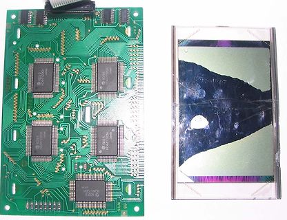
in „LCD LM234D“ · Mikrocontroller und Digitale Elektronik · · Platinenfotos
-
Bild
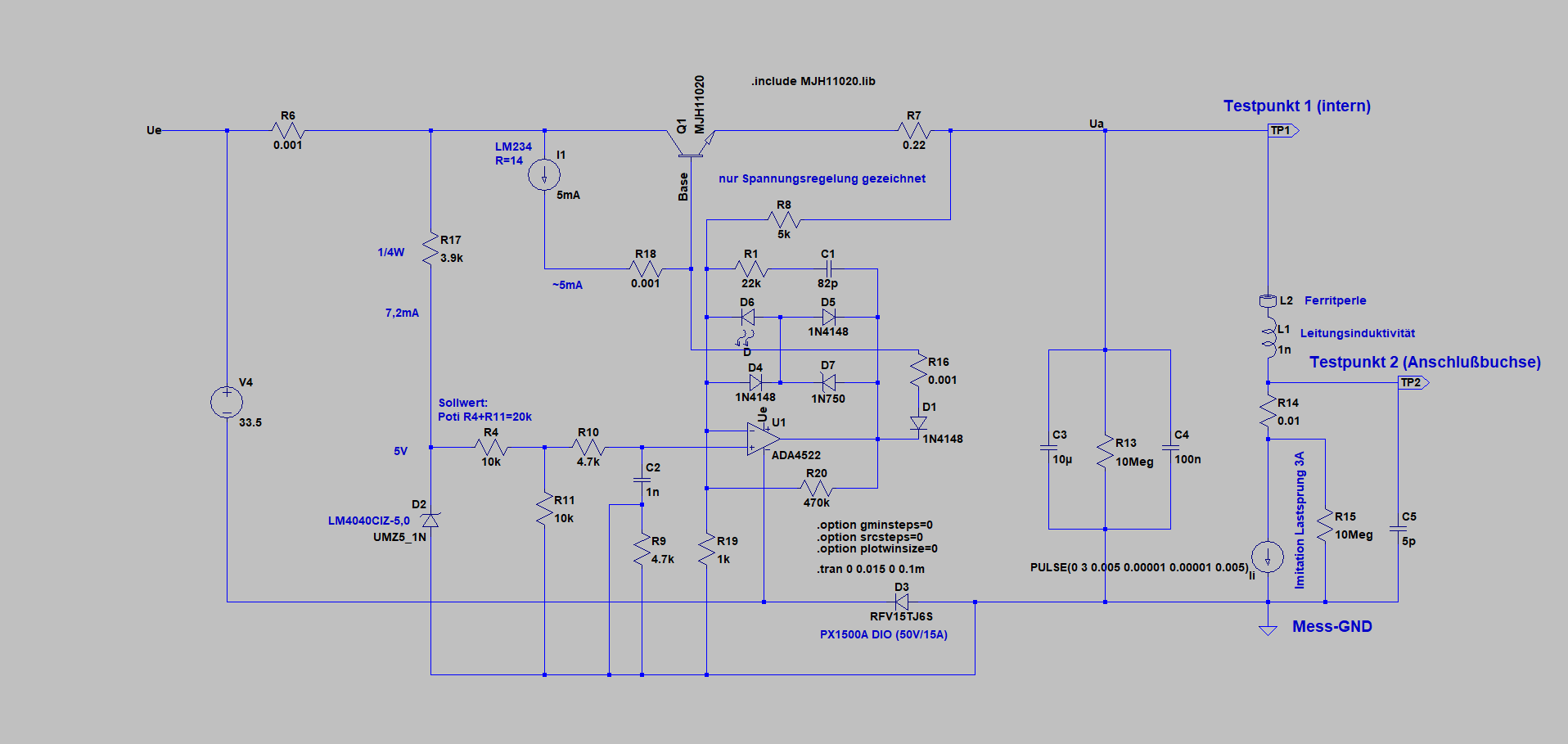
Schaltplan einer Spannungsregelung
Ue R6 0.01 LM234 R=14 I1 5mA Q1 MJH1020 Base nur Spannungsregelung gezeichnet R8 5k Ua Testpunkt 1 (intern) TP1 L2 Ferritperle L1 Leistungsinduktivitat 1n Testpunkt 2 (Anschlussbuchse) TP2 R14 0.01 R16 0.01 D1 1N4148
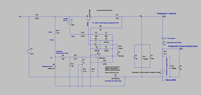
in „Nebenprojekt: Analoges Labornetzteil inkl. Schaltplan und Messungen“ · Projekte & Code · · Schaltpläne
-
Bild
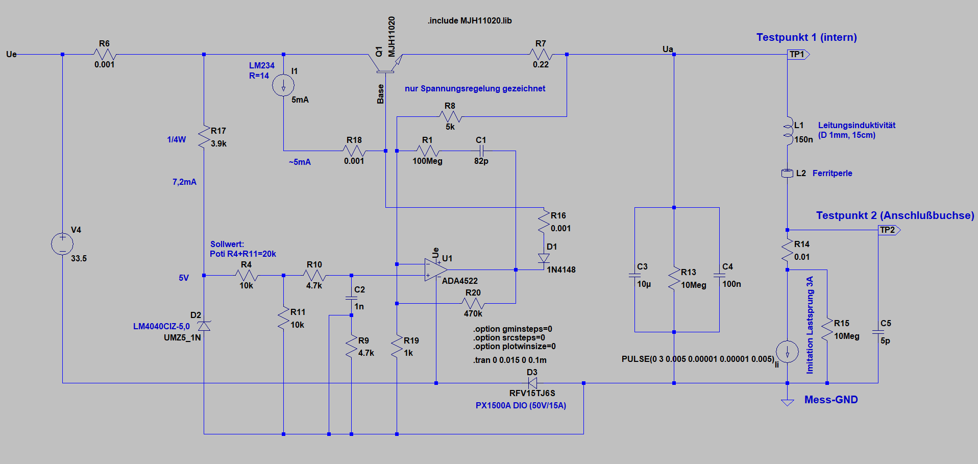
Schaltplan einer Simulation einer Spannungsregelung
Ue R6 0.01 LM234 R=14 I1 5mA Q1 MJH1020 Base nur Spannungsregelung gezeichnet R8 5k R17 3.9k R1 0.01 C1 82p Ua Testpunkt 1 (intern) TP1 L1 Leitungsinduktivität 150n (D 1mm, 15cm) R18 ~5mA 7,2mA V4 3.5 Sollwert: Poti
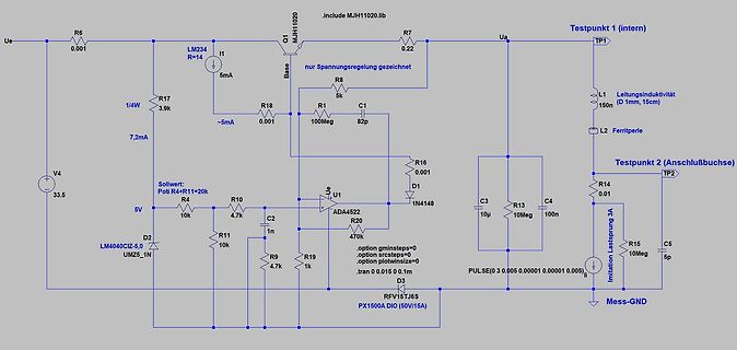
in „Nebenprojekt: Analoges Labornetzteil inkl. Schaltplan und Messungen“ · Projekte & Code · · Schaltpläne
-
Bild
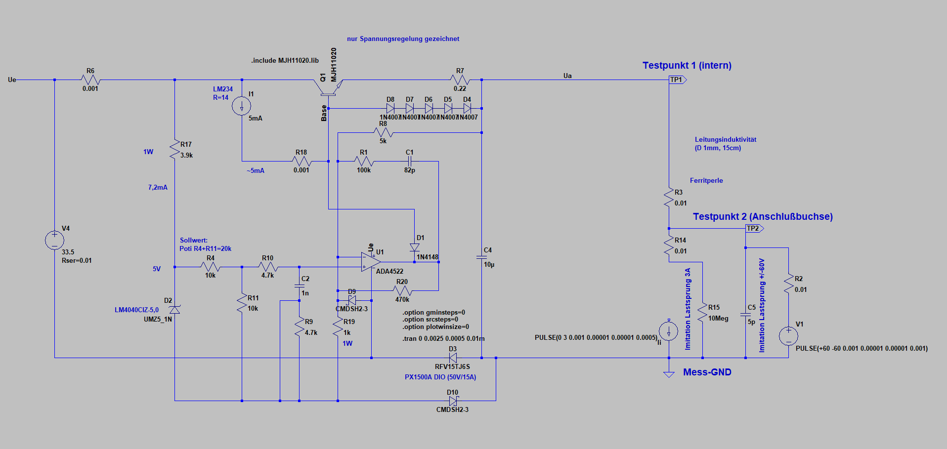
Schaltplan einer Spannungsregelung
nur Spannungsregelung gezeichnet Ue R6 0.01 LM234 R14 I1 5mA MJH1020 Q1 Base D8 1N407 R8 5k D7 1N407 D6 1N407 D4 1N407 R7 0.2 Ua TP1 (intern Leitungsinduktivitat (D 1mm, 15cm) R3 0.01 Ferritperle TP2 (Anschlußbuchse) R14 0.01 R18 0.01 C1 82p R1 10k
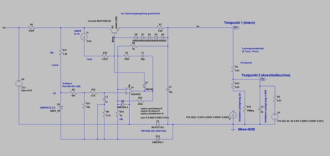
in „Nebenprojekt: Analoges Labornetzteil inkl. Schaltplan und Messungen“ · Projekte & Code · · Schaltpläne
-
Bild
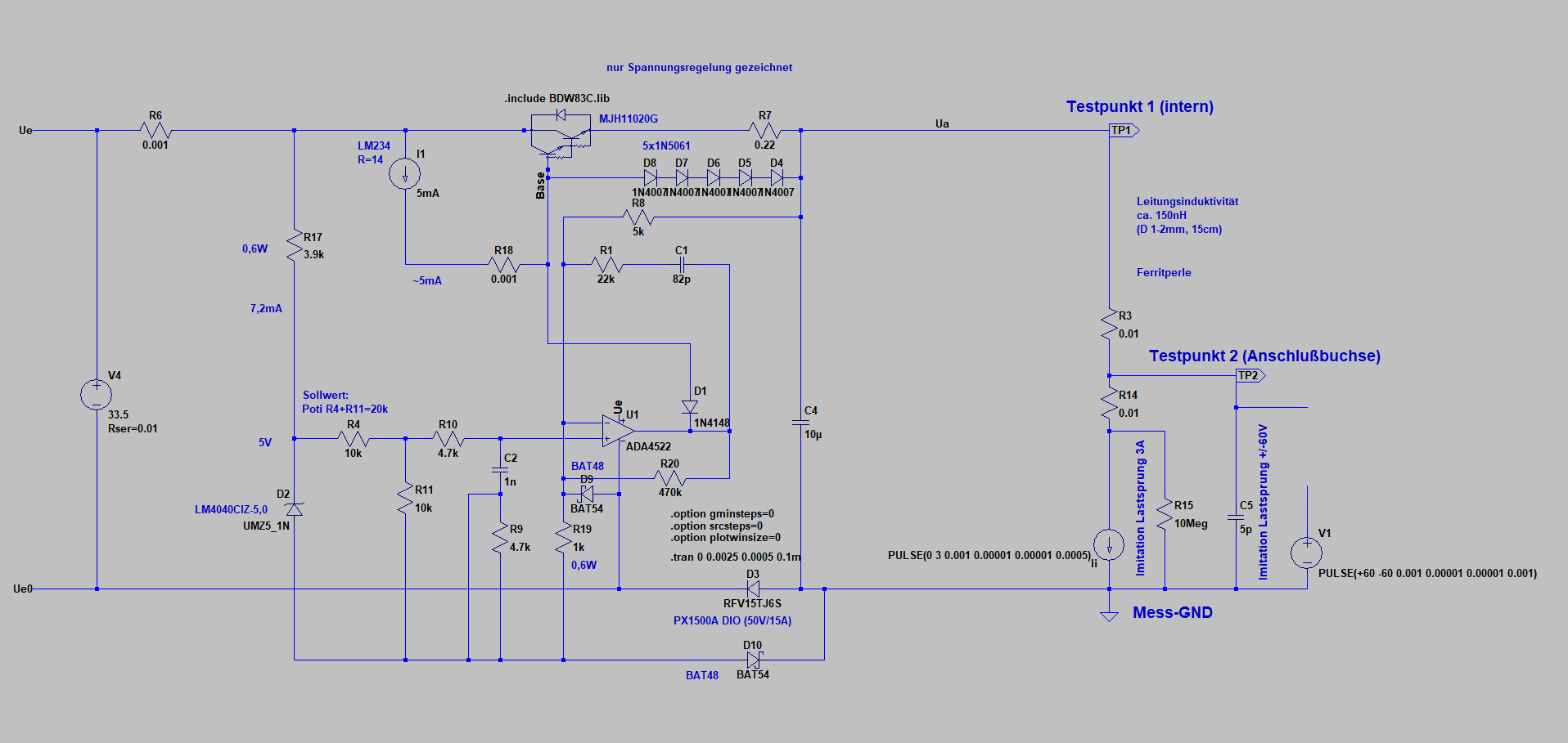
Schaltplan einer Spannungsregelung
nur Spannungsregelung gezeichnet, include BDW3C.lib, Testpunkt 1 (intern), Ue, R6, 0.01, LM234, R14, I1, 5mA, Base, 5x1N5061, R7, 0.2, Ua, TP1, Leitungsinduktivität ca. 150mH (D 1-2mm, 15cm), R17, 0,6W, 3.9k, R10, -5mA, D7, D6, D5, D4, 1N40x, N40x, N40x, N40x, N407, R8, 5k, Ferritperle, R3,
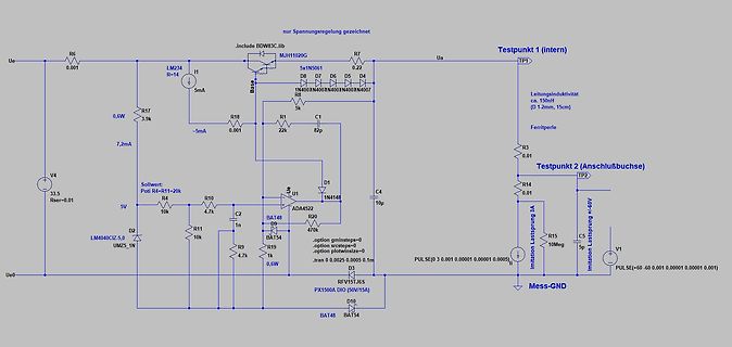
in „Nebenprojekt: Analoges Labornetzteil inkl. Schaltplan und Messungen“ · Projekte & Code · · Schaltpläne
-
PDF
kicad_8450_dcm_liste_neu_v3.pdf
Micropower Voltage Reference, SOT-23 LM134H 1μA to 10mA 3-Terminal Adjustable Current Source, TO-46 LM234Z-3 1μA to 10mA 3-Terminal Adjustable Current Source, TO-92 LM234Z-6 1μA to 10mA 3-Terminal Adjustable Current Source, TO-92 LM285D-1.2 1.235V Micropower Voltage Reference Diodes, SO-8 LM285D-2.5 2.500V
in „KiCAD Eeschema, Bibliotheksdokumentation *.dcm als PDF-Datei“ · Platinen ·