-
PDF
ChargePump_LM2664_40mA.pdf
Product Sample & Technical Tools & Support & Folder Buy Documents Software Community LM2664 SNVS005E –NOVEMBER 1999–REVISED DECEMBER 2014 LM 2664Sw itchedC apacitorVoltageC onverter 1 Features 3 Description The LM2664 CMOS charge-pump voltage converter • Inverts Input Supply Voltage • 6-Pin
in „Geregelte negative Spannung mit LM2664 und LP2980 - geht das überhaupt?“ · Analoge Elektronik und Schaltungstechnik ·
-
Bild
Mathematische Formel für den Ausgangswiderstand
ROUT ≅ 2RSW + 2 / (fOSC x C1) + 4ESRC1 + ESRC2

in „Geregelte negative Spannung mit LM2664 und LP2980 - geht das überhaupt?“ · Analoge Elektronik und Schaltungstechnik · · Screenshots
-
Bild
Formel zur Berechnung der Ausgangsspannungswelligkeit
The peak-to-peak output voltage ripple is determined by the oscillator frequency, the capacitance and ESR of the output capacitor C2: vRIPPLE = IL / (fOSC * C2) + 2 * IL * ESRC2 (2)

in „Geregelte negative Spannung mit LM2664 und LP2980 - geht das überhaupt?“ · Analoge Elektronik und Schaltungstechnik · · Screenshots
-
Bild
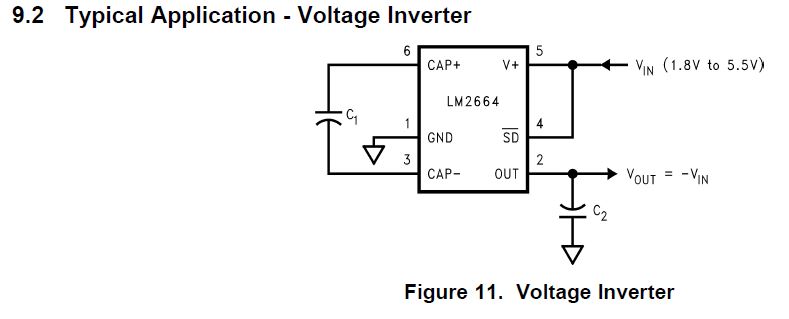
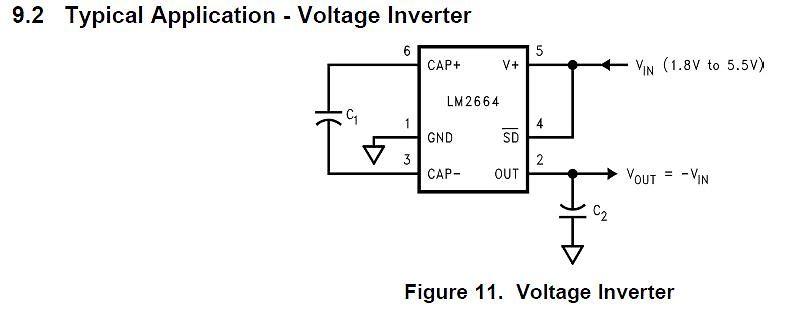
Schaltplan eines Spannungsinverters
9.2 Typical Application - Voltage Inverter 6 CAP+ 5 V+ VIN (1.8V to 5.5V) LM2664 4 SD 1 GND 3 CAP- 2 OUT VIN VOUT = -VIN C1 C2 Figure 11. Voltage Inverter
in „Geregelte negative Spannung mit LM2664 und LP2980 - geht das überhaupt?“ · Analoge Elektronik und Schaltungstechnik · · Screenshots
-
Bild
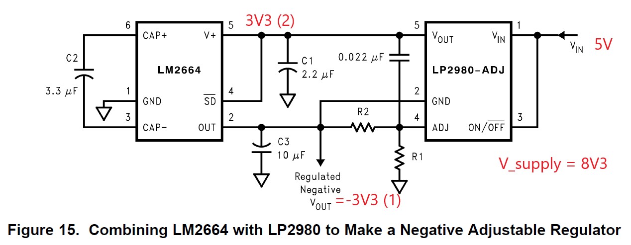
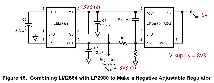
Schaltplan eines negativen einstellbaren Reglers
GND 4 R2 C3 10 µF R1 2 VOUT Regulated Negative VOUT = -3V3 (1) V_supply = 8V3 Figure 15. Combining LM2664 with LP2980 to Make a Negative Adjustable Regulator
in „Geregelte negative Spannung mit LM2664 und LP2980 - geht das überhaupt?“ · Analoge Elektronik und Schaltungstechnik · · Schaltpläne