-
Datei
rf_defines.h
NRF24L01_EN_CRC 3 #define NRF24L01_CRCO 2 #define NRF24L01_PWR_UP 1 #define NRF24L01_PRIM_RX 0 /* Enable auto acknowledgment*/ #define NRF24L01_ENAA_P5 5 #define NRF24L01_ENAA_P4 4 #define NRF24L01_ENAA_P3 3 #define NRF24L01_ENAA_P2 2 #define NRF24L01_ENAA_P1 1 #define NRF24L01_ENAA_P0 0 /* Enable rx addresses */ #define NRF24L01_ERX_P5 5 #define NRF24L01_ERX_P4 4 #define NRF24L01_ERX_P3 3 #define NRF24L01_ERX_P2 2 #define
in „[STM32F4xx] NRF24L01+ Funkmodul Source Code“ · Projekte & Code ·
-
Datei
nrf24l01.c
NRF24L01_EN_CRC 3 #define NRF24L01_CRCO 2 #define NRF24L01_PWR_UP 1 #define NRF24L01_PRIM_RX 0 /* Enable auto acknowledgment*/ #define NRF24L01_ENAA_P5 5 #define NRF24L01_ENAA_P4 4 #define NRF24L01_ENAA_P3
in „Wer hat noch Ärger mit NRF24L01+ Funkmodulen?“ · Mikrocontroller und Digitale Elektronik ·
-
Datei
nrf24l01_drv.c
Pipes 0 - 1 setzen */ RF_WriteRegSingle(NRF24L01_REG_EN_RXADDR, (1 << NRF24L01_ERX_P0) | (1 << NRF24L01_ERX_P1) \ | (1 << NRF24L01_ERX_P2) | (1 << NRF24L01_ERX_P3) | (1 << NRF24L01_ERX_P4) | (1 << NRF24L01_ERX_P5) ); /* Adresse fuer ACK/Payload
in „[STM32F4xx] NRF24L01+ Funkmodul Source Code“ · Projekte & Code ·
-
Datei
nrf24l01_drv.c
Pipes 0 - 1 setzen */ RF_WriteRegSingle(NRF24L01_REG_EN_RXADDR, (1 << NRF24L01_ERX_P0) | (1 << NRF24L01_ERX_P1) \ | (1 << NRF24L01_ERX_P2) | (1 << NRF24L01_ERX_P3) | (1 << NRF24L01_ERX_P4) | (1 << NRF24L01_ERX_P5) ); /* Adresse fuer ACK/Payload
in „Basteltip: STM32F103 DIP40 Board“ · Mikrocontroller und Digitale Elektronik ·
-
Datei
nrf24l01_drv.c
Pipes 0 - 1 setzen */ RF_WriteRegSingle(NRF24L01_REG_EN_RXADDR, (1 << NRF24L01_ERX_P0) | (1 << NRF24L01_ERX_P1) \ | (0 << NRF24L01_ERX_P2) | (0 << NRF24L01_ERX_P3) \ | (0 << NRF24L01_ERX_P4) | (0 << NRF24L01_ERX_P5) ); /* Adressen setzen */ RF_WriteRegMulti
in „EmBitz Debugging Problem mit STM32F103“ · Mikrocontroller und Digitale Elektronik ·
-
Datei
nrf24l01_drv.c
Pipes 0 - 1 setzen */ RF_WriteRegSingle(NRF24L01_REG_EN_RXADDR, (1 << NRF24L01_ERX_P0) | (1 << NRF24L01_ERX_P1) \ | (0 << NRF24L01_ERX_P2) | (0 << NRF24L01_ERX_P3) \ | (0 << NRF24L01_ERX_P4) | (0 << NRF24L01_ERX_P5) ); /* Adressen setzen */ RF_WriteRegMulti
in „Kleine Frage zu Makros“ · Mikrocontroller und Digitale Elektronik ·
-
Datei
nrf24l01.c
Pipes 0 - 5 setzen */ RF_WriteRegSingle(NRF24L01_REG_EN_RXADDR, (1 << NRF24L01_ERX_P0) | (1 << NRF24L01_ERX_P1) | (1 << NRF24L01_ERX_P2) \ | (1 << NRF24L01_ERX_P3)| (1 << NRF24L01_ERX_P4)| (1 << NRF24L01_ERX_P5)); /* Adresse fuer ACK/Payload setzen
in „NRF24L01+ auf STM32F103: Ich weiss nicht mehr weiter :-(“ · Mikrocontroller und Digitale Elektronik ·
-
Datei
nrf24l01.c
= Max */ RF_WriteRegSingle(NRF24L01_REG_RF_SETUP, (1 << NRF24L01_RF_DR_LOW) | (0 << NRF24L01_RF_DR_HIGH) | 0x06); /* Erlaubte Pipe 0 setzen, alle anderen aus */ RF_WriteRegSingle(NRF24L01_REG_EN_RXADDR, (1 << NRF24L01_ERX_P0)); RF_WriteRegMulti
in „[STM32F4xx] NRF24L01+ Funkmodul Source Code“ · Projekte & Code ·
-
Datei
nrf24l01.c
); /* Retransmission 15 und Delay 4000us (nicht erforderlich) */ RF_WriteRegSingle(NRF24L01_REG_SETUP_RETR,0xff); /* Erlaubte Pipes 0 - 5 setzen */ RF_WriteRegSingle(NRF24L01_REG_EN_RXADDR, (1 << NRF24L01_ERX_P0) | (1 << NRF24L01_ERX_P1) | (1 << NRF24L01_ERX_P2) \ | (1 << NRF24L01_ERX_P3
in „NRF24L01: Handauflegen hilft?“ · Mikrocontroller und Digitale Elektronik ·
-
Datei
nrf24l01.c
= Max */ RF_WriteRegSingle(NRF24L01_REG_RF_SETUP, (1 << NRF24L01_RF_DR_LOW) | (0 << NRF24L01_RF_DR_HIGH) | 0x06); /* Erlaubte Pipe 0 setzen, alle anderen aus */ RF_WriteRegSingle(NRF24L01_REG_EN_RXADDR, (1 << NRF24L01_ERX_P0)); RF_WriteRegMulti
in „STM32F4 und NRF24L01: Frage zu Interrupts“ · Mikrocontroller und Digitale Elektronik ·
-
Datei
nrf24l01_drv.c
Pipes 0 - 5 setzen */ RF_WriteRegSingle(NRF24L01_REG_EN_RXADDR, (1 << NRF24L01_ERX_P0) | (1 << NRF24L01_ERX_P1) \ | (0 << NRF24L01_ERX_P2) | (0 << NRF24L01_ERX_P3) \ | (0 << NRF24L01_ERX_P4) | (0 << NRF24L01_ERX_P5) ); /* Adressen setzen */ RF_WriteRegMulti
in „NRFL24L01+ - Immer Ärger mit den Paarungen“ · Mikrocontroller und Digitale Elektronik ·
-
Datei
nrf24l01.c
---- */ void RF_PowerUpTX() { CE_LOW; RF_WriteRegSingle(NRF24L01_REG_STATUS,0x70); // Power Up, CRC8 RF_WriteRegSingle(NRF24L01_REG_CONFIG, (0 << NRF24L01_PRIM_RX) | (1 << NRF24L01_MASK_MAX_RT) | (1 << NRF24L01_EN_CRC) | (0 << NRF24L01_CRCO) | (1 << NRF24L01_PWR_UP
in „[STM32F4xx] NRF24L01+ Funkmodul Source Code“ · Projekte & Code ·
-
Datei
nrf24l01.c
Max */ RF_WriteRegSingle(NRF24L01_REG_RF_SETUP, (0 << NRF24L01_RF_DR_LOW) | (0 << NRF24L01_RF_DR_HIGH) | 0x06); /* Erlaubte Pipe 0 setzen, alle anderen aus */ RF_WriteRegSingle(NRF24L01_REG_EN_RXADDR, (1 << NRF24L01_ERX_P0)); RF_WriteRegMulti
in „NRF24L01 SPI Problem bringt mich noch zum Wahnsinn!“ · Mikrocontroller und Digitale Elektronik ·
-
Datei
nrf24l01.c
, (1 << NRF24L01_RF_DR_LOW) | (0 << NRF24L01_RF_DR_HIGH) | 0x06); /* Erlaubte Pipe 0 setzen, alle anderen aus */ RF_WriteRegSingle(NRF24L01_REG_EN_RXADDR, (1 << NRF24L01_ERX_P0)); /* Adressen setzen */ RF_WriteRegSingle
in „GCC Optimierung killt Funktion“ · Mikrocontroller und Digitale Elektronik ·
-
Datei
tools.c
_SetRF(TM_NRF24L01_DataRate_1M,TM_NRF24L01_OutputPower_0dBm); TM_NRF24L01_SetMyAddress(MyAddress); TM_NRF24L01_SetTxAddress(TxAddress); // Ganze Blocks übertragen GPIO_SetPin(GPIOD,LED_ORANGE); for (uint16_t i = 0;i
in „Organisation der Header und Includes“ · Mikrocontroller und Digitale Elektronik ·
-
Datei
tools.c
Init(RF_CHANNEL,PAKETSIZE); TM_NRF24L01_SetRF(TM_NRF24L01_DataRate_1M,TM_NRF24L01_OutputPower_0dBm); TM_NRF24L01_SetMyAddress(MyAddress); TM_NRF24L01_SetTxAddress(TxAddress); // Ganze Blocks übertragen GPIO_SetPin(HWPORT,LED_ORANGE); for
in „Organisation der Header und Includes“ · Mikrocontroller und Digitale Elektronik ·
-
Datei
tools.c
Init(RF_CHANNEL,PAKETSIZE); TM_NRF24L01_SetRF(TM_NRF24L01_DataRate_1M,TM_NRF24L01_OutputPower_0dBm); TM_NRF24L01_SetMyAddress(MyAddress); TM_NRF24L01_SetTxAddress(TxAddress); // Ganze Blocks übertragen GPIO_SetPin(HWPORT,LED_ORANGE); for
in „Organisation der Header und Includes“ · Mikrocontroller und Digitale Elektronik ·
-
Datei
nrf24l01.h
RF_Response_t; /* Datenrate des Moduls */ typedef enum { Rate_250kBit = 0, Rate_1Mbit, Rate_2Mbit } NRF24L01_DataRate_t; /* Ausgangs Power Selektoren */ typedef enum { NRF24L01_Power_Min = 0, // -22dbm NRF24L01_Power_Low, // -18dm NRF24L01_Power_High, // -12dbm NRF24L01_Power_Max // 0dm } NRF24L01_Power_t
in „[STM32F4xx] NRF24L01+ Funkmodul Source Code“ · Projekte & Code ·
-
Datei
nrf24l01.h
#ifndef NRF24L01_H_INCLUDED #define NRF24L01_H_INCLUDED /* -------------- Standard Include Files ----------------- */ #include <stdint.h> #include <stdbool.h> /* --------------- Special Include Files / Librarys --
in „[STM32F4xx] NRF24L01+ Funkmodul Source Code“ · Projekte & Code ·
-
Datei
nrf24l01.h
#ifndef NRF24L01_H_INCLUDED #define NRF24L01_H_INCLUDED /* -------------- Standard Include Files ----------------- */ /* -------------- Special Include Files / Librarys ------ */ /* -------------- Projekt Include
in „NRF24L01+ auf STM32F103: Ich weiss nicht mehr weiter :-(“ · Mikrocontroller und Digitale Elektronik ·
-
Datei
nrf24l01_drv.h
#ifndef NRF24L01_H_INCLUDED #define NRF24L01_H_INCLUDED /* -------------- Standard Include Files ----------------- */ /* -------------- System Include Files / Librarys -------- */ #include "stm32f10x_conf.h" /* --
in „Basteltip: STM32F103 DIP40 Board“ · Mikrocontroller und Digitale Elektronik ·
-
Datei
nrf24l01_drv.h
#ifndef NRF24L01_H_INCLUDED #define NRF24L01_H_INCLUDED /* -------------- Standard Include Files ----------------- */ /* -------------- System Include Files / Librarys -------- */ #include "stm32f10x_conf.h" /* --
in „[STM32F4xx] NRF24L01+ Funkmodul Source Code“ · Projekte & Code ·
-
 Bild
Bild
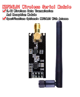
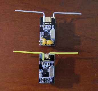
NRF24L01 Funkmodul mit Antenne
NRF24L01 Wireless Serial Module 2.4G Wireless Data Transmission And Reception Module Specifications Optional: NRF24L01 With Antenna
in „Umbau NRF24L01 mit Dipolantenne“ · HF, Funk und Felder · · Platinenfotos
-
PDF
NRF_Modul.pdf
NRF_SetRXState(); NRF_CE_Hi; } Page: 3 C:\Users\s.schmidl\Documents\AVR\program_avr\RF_Relay_Box V1.3\NRF24L01_SSPI.c /*********************************/ /********* NRF 24L01 *************/ /**** with Software SPI **********/ /*********************************/ #include <stdint.h> #include <avr/io.h> #include <util/delay.h> #include <avr/interrupt.h> #include "NRF24L01_Dec.h" #include "SoftwareSPI_Dec.h" #include "Converter.h" extern unsigned char Payload[32]; extern unsigned char Received[3][32]; extern unsigned char RFChannel; extern volatile uint8_t WorkerFlag
in „ATmega 164P USART funktioniert nur mit beschaltung auf PB7“ · Mikrocontroller und Digitale Elektronik ·
-
Datei
nrf24l01_usr.c
/* ******************************************** Modul : NRF24L01_USR Applikations Routinen auf Basis des NRF24L01 Treibers NRF24L01_DRV Level 2 Autor : Christian Julius ******************************************** */ /* -------------- Standard Include Files ---
in „[STM32F4xx] NRF24L01+ Funkmodul Source Code“ · Projekte & Code ·
-
Datei
nrf24l01_usr.c
/* ******************************************** Modul : NRF24L01_USR Applikations Routinen auf Basis des NRF24L01 Treibers NRF24L01_DRV Level 2 Autor : Christian Julius ******************************************** */ /* -------------- Standard Include Files ---
in „EmBitz Debugging Problem mit STM32F103“ · Mikrocontroller und Digitale Elektronik ·
-
Datei
nrf24l01_usr.c
/* ******************************************** Modul : NRF24L01_USR Applikations Routinen auf Basis des NRF24L01 Treibers NRF24L01_DRV Level 2 Autor : Christian Julius ******************************************** */ /* -------------- Standard Include Files ---
-
Datei
nrf24l01.c
include <stdlib.h> #include <stdint.h> #include <avr/pgmspace.h> #include <avr/interrupt.h> #include "nrf24l01.h" volatile uint8_t nRF_data_available=0; uint8_t op_status; #define CE_HIGH() PORTG |= (1<<PG2) #define CE_LOW() PORTG &= ~(1<<PG2) #define CSN_HIGH() PORTC |= (1<<PC7) #define CSN_LOW() PORTC &=
in „RFM12 vs nrf24l01“ · Mikrocontroller und Digitale Elektronik ·
-
Datei
nrf24l01.h
#ifndef _nrf24l01_h_ #define _nrf24l01_h_ #include <stdint.h> #define MAX_PACKET_LEN 32// max value is 32 //************************FSK COMMAND and REGISTER****************************************// // SPI(RFM70) commands
in „RFM12 vs nrf24l01“ · Mikrocontroller und Digitale Elektronik ·
-
Datei
nrf24l01.c
// CE @ RC1 // CSN @ RC2 #include "nrf24l01.h" #define CE_HIGH() RC1_bit=1 #define CE_LOW() RC1_bit=0 #define CSN_HIGH() RC2_bit=1 #define CSN_LOW() RC2_bit=0 char nRF_data_available=0; char op_status; char RX0_Address[] ={0x34,0x43,0x10,0x11,0x11
in „RFM12 vs nrf24l01“ · Mikrocontroller und Digitale Elektronik ·
-
Datei
nrf24l01.h
FIFO_STATUS_TX_EMPTY 0x10 #define FIFO_STATUS_RX_FULL 0x02 #define FIFO_STATUS_RX_EMPTY 0x01 void SPI_init(); void nrf24l01_Initialize(); char SPI_transfer(char value ); void SPI_Write_Reg(char reg, char value) ; char SPI_Read_Reg(char reg); void SPI_Read_Buf(char reg, char *pBuf, char length); void SPI_Write_Buf(char
in „RFM12 vs nrf24l01“ · Mikrocontroller und Digitale Elektronik ·
-
Datei
nrf24l01_usr.h
#ifndef NRF24L01_USR_H_INCLUDED #define NRF24L01_USR_H_INCLUDED /* -------------- Standard Include Files ----------------- */ /* ---------------System Include Files / Librarys -------- */ #include "stm32f10x_conf.h
in „[STM32F4xx] NRF24L01+ Funkmodul Source Code“ · Projekte & Code ·
-
 Bild
Bild
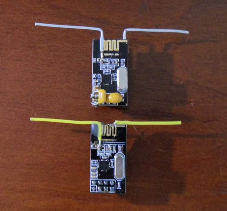
Zwei kleine Leiterplatten mit Antennen
nrf24l01_antenne.jpg
in „Umbau NRF24L01 mit Dipolantenne“ · HF, Funk und Felder · · Platinenfotos
-
Datei
NRF24l01-Sender.ino
#include <Arduino.h> #include <SPI.h> #include <RH_NRF24.h> #include "LowPower.h" // Singleton instance of the radio driver RH_NRF24 nrf24; uint8_t pos = 4; uint8_t counter = 0; uint8_t chk = 0; void setup() { Serial.begin(9600); while (!Serial) ; // wait for serial port to connect. Needed for Leonardo only if (!nrf24.init()) { Serial.println("init failed"); } // Defaults after init are 2.402 GHz (channel 2), 2Mbps, 0dBm if (!nrf24.setChannel(3)) { Serial.println("setChannel failed"); } if (!nrf24.setRF(RH_NRF24::DataRate2Mbps, RH_NRF24::TransmitPower0dBm)) { Serial.println("setRF failed"); } Serial.println
in „Arduino mit NRF04l01 - Problem im PowerDown“ · Mikrocontroller und Digitale Elektronik ·
-
PDF
TOBBY.pdf
Accelerometer analog 3-way (X,Y,Z) Balancer No need of a third wheel (like a Segway) Communication Wireless NRF24L01+ compatible interface or USART bluethooth interface or WLAN Position Detection LPDS (Local Position Detection System) triggered by radio-signal and measured by sonar (precision +/- 5..10mm) for complete
in „TOBBY THE ROBBY“ · Markt ·
-
Datei
arduino328.ino
(AM2302), AM2321 #define DHTPIN 2 // what digital pin we're connected to #define CE_PIN 8 // CE NRF24L01 #define CSN_PIN 7 // CSN NRF24L01 #define RF_CHANNEL 75 // Der Transfer Datensatz struct data_t { uint16_t id; uint16_t nr; float temperatur_1; float temperatur_2; float feuchte; float ubatt; } __
in „NRF24L01+ auf STM32F103: Ich weiss nicht mehr weiter :-(“ · Mikrocontroller und Digitale Elektronik ·
-
Datei
main.c
stdint.h> #include <time.h> /* Projekt Includes */ #include "main.h" #include "sysinit.h" #include "nrf24l01_drv.h" #include "nrf24l01_usr.h" #include "isrhdl.h" #include "HCT595.h" #include "backup.h" #include "lcd_init.h" #include "lcd_usr.h" #include "rtc_user.h" /* Private typedef -------------------
in „Timer Interrupt STM32F103“ · Mikrocontroller und Digitale Elektronik ·
-
Datei
iO.c
(1 << ADEN ) | (1 << ADPS2 ) | (1 << ADPS1 ) | (1 << ADPS0 ); while(1) { //Initialisierung von NRF24L01 wl_module_init(); _delay_ms(50); sei(); wl_module_tx_config(wl_module_TX_NR_0); //ADC auslesen l = adc_read(1); //DHT22 auslesen if(dht_gettemperaturehumidity(&temperature, &humidity) != -1) { } else
in „AVR Programm läuft nur fehlerfrei direkt nach Programmierung mittels ISP“ · Mikrocontroller und Digitale Elektronik ·
-
Datei
niO.c
(1 << ADEN ) | (1 << ADPS2 ) | (1 << ADPS1 ) | (1 << ADPS0 ); while(1) { //Initialisierung von NRF24L01 wl_module_init(); _delay_ms(50); sei(); wl_module_tx_config(wl_module_TX_NR_0); //ADC auslesen l = adc_read(1); //DHT22 auslesen if(dht_gettemperaturehumidity(&temperature, &humidity) != -1) { } else
in „AVR Programm läuft nur fehlerfrei direkt nach Programmierung mittels ISP“ · Mikrocontroller und Digitale Elektronik ·
-
Datei
attiny84_24ghz.ino
(AM2302), AM2321 #define DHTPIN 2 // what digital pin we're connected to #define CE_PIN 8 // CE NRF24L01 #define CSN_PIN 7 // CSN NRF24L01 #define RF_CHANNEL 80 /* ACK Datensatz */ struct { uint8_t feuchte_enable, // 1 = Sende Feuchtedaten temp1_enable, // 1 = Sende Temp Sensor 1 Daten temp2_enable,
in „[STM32F4xx] NRF24L01+ Funkmodul Source Code“ · Projekte & Code ·
-
Datei
arduino328.ino
(AM2302), AM2321 #define DHTPIN 2 // what digital pin we're connected to #define CE_PIN 8 // CE NRF24L01 #define CSN_PIN 7 // CSN NRF24L01 #define RF_CHANNEL 75 /* ACK Datensatz */ struct { uint8_t feuchte_enable, // 1 = Sende Feuchtedaten temp1_enable, // 1 = Sende Temp Sensor 1 Daten temp2_enable,
in „Zeigt her eure Kunstwerke (2017-2019)“ · Projekte & Code ·
-
Datei
wl_module.c
actual address to be used. It should be sized // according to the tx_addr length specified to the nrf24l01. //unsigned int len is the length of the address. Its value should be specified // according to the tx_addr length specified to the nrf24l01. extern void wl_module_set_tx_addr(uint8_t * address, uint8
in „2,4 Ghz Kommunikation“ · Mikrocontroller und Digitale Elektronik ·
-
Datei
wl_module.c
actual address to be used. It should be sized // according to the tx_addr length specified to the nrf24l01. //unsigned int len is the length of the address. Its value should be specified // according to the tx_addr length specified to the nrf24l01. extern void wl_module_set_tx_addr(uint8_t * address, uint8
in „NRF24L01 und Atmega328P“ · Mikrocontroller und Digitale Elektronik ·
-
Datei
wl_module.c
actual address to be used. It should be sized // according to the tx_addr length specified to the nrf24l01. //unsigned int len is the length of the address. Its value should be specified // according to the tx_addr length specified to the nrf24l01. extern void wl_module_set_tx_addr(uint8_t * address, uint8
in „NRF24L01 und Atmega328P“ · Mikrocontroller und Digitale Elektronik ·
-
Datei
wl_module.c
actual address to be used. It should be sized // according to the tx_addr length specified to the nrf24l01. //unsigned int len is the length of the address. Its value should be specified // according to the tx_addr length specified to the nrf24l01. extern void wl_module_set_tx_addr(uint8_t * address, uint8
in „NRF24L01 und Atmega328P“ · Mikrocontroller und Digitale Elektronik ·
-
PDF
RF_Relay_Box_V1.3.pdf
include <avr/io.h> #include <stdint.h> #include <util/delay.h> #include <avr/interrupt.h> #include "NRF24L01_Dec.h" #include "Pin_changed_Sensing_Dec.h" #include "RF_Relay_Box_V1.3_Dec.h" #include "SoftwareSPI_Dec.h" #include "Converter.h" #include "SwitchLights_Dec.h" #include "PWM_Dec_ATmega164P.h" #include
in „ATmega 164P USART funktioniert nur mit beschaltung auf PB7“ · Mikrocontroller und Digitale Elektronik ·
-
Datei
nRF24L01_.h
OR IN CONNECTION WITH THE SOFTWARE OR THE USE OR OTHER DEALINGS IN THE SOFTWARE. */ #ifndef _LIB_NRF24L01_H_ #define _LIB_NRF24L01_H_ #include <avr/io.h> #include <stdbool.h> #include <spi.h> /****************************************************************************** * Project Specific Settings (adapt
in „nRF24L01+ Funkmodul - Auto Acknowledgement sendet keine Payload“ · Mikrocontroller und Digitale Elektronik ·
-
 Bild
Bild
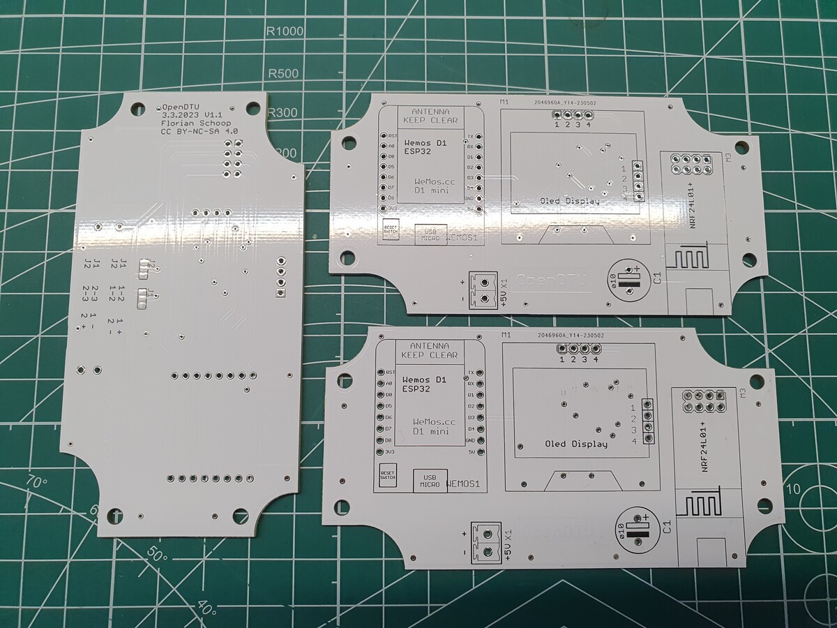
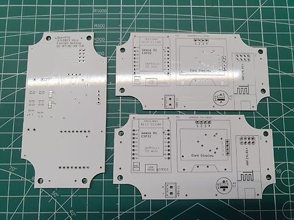
Zwei weiße Leiterplatten mit Bestückungsdruck
4.0 ANTENNA KEEP CLEAR Wemos D1 ESP32 Wemos.cc D1 mini J1 J2 J3 J4 1-2 2-3 3-4 4-1 OLED Display NRF24L01+ M1 M3 C1 +5V USB MICRO
in „[V] PCBs für OpenDTU/Ahoy (Kommunikation mit Hoymiles Wechselrichtern)“ · Markt · · Platinenfotos
-
PDF
Envilight_DRV450B022017.pdf
alle vier Kanäle gemeinsam eingestellt. Technische Daten Features WiFi IEEE802.11b/g/n (optional) NRF24L01 GFSK (optional) Eingangsspannung Max. 48V DC LED-Spannung Bis zu 42V DC LED-Strom Max. 2A pro Kanal Anzahl Kanäle 4 Helligkeitssteuerung Pro Kanal: 800 Stufen Strombereich 0..2A in 200 Stufen Abmessungen
-
Datei
0.4.25_SD_Setup.diff
invRetry\" value=\"{INV_RETRIES}\"/><p class=\"des\">Pinout (Wemos)</p>{PINOUT}<p class=\"des\">Radio (NRF24L01+)</p><label for=\"rf24Power\">Amplifier Power Level</label><select name=\"rf24Power\">{RF24}</select><p class=\"des\">MQTT</p><label for=\"mqttAddr\">Broker / Server IP</label><input type=\"text\"
in „Wechselrichter Hoymiles HM-xxxx 2,4 GhZ Nordic Protokoll?“ · Mikrocontroller und Digitale Elektronik ·