-
Datei
PCA9635.h
PCA9635_AI_CTLONLY 0x6 #define PCA9635_AI_CTLPWMONLY 0x7 #define PCA9635_REG_MODE1 0x00 #define PCA9635_REG_MODE2 0x01 #define PCA9635_REG_PWM0 0x02 #define PCA9635_REG_PWM1 0x03 #define PCA9635_REG_PWM2
in „Funktion funktionieren nicht aber warum?“ · Mikrocontroller und Digitale Elektronik ·
-
Datei
PCA9635.h
PCA9635_AI_CTLONLY 0x6 #define PCA9635_AI_CTLPWMONLY 0x7 #define PCA9635_REG_MODE1 0x00 #define PCA9635_REG_MODE2 0x01 #define PCA9635_REG_PWM0 0x02 #define PCA9635_REG_PWM1 0x03 #define PCA9635_REG_PWM2
in „Funktionsaufruf Funktioniert nicht richtig..warum?“ · Mikrocontroller und Digitale Elektronik ·
-
Datei
Main.c
TWIM_Init (1000)) { printf ("Error in initiating TWI interface\n"); while (1); } /** Initzialisiere PCA9635 **/ PCA9635_OFF(); PCA9635(); sei(); /** Endlosschleife **/ while(1) { /** Write byte(s) to the slave **/ if( get_key_press( 1<<KEY0 )) { PORTD = PORTD | ( 1<<PD5 ); Full_On(); //PCA9635(); } if ( get_key_press( 1<<KEY1 )) { PCA9635_OFF(); PCA9635(); PORTD &= ~( 1<<PD5 ); } } return 0; }
in „Funktion funktionieren nicht aber warum?“ · Mikrocontroller und Digitale Elektronik ·
-
Datei
PCA9635.c
#include <stdio.h> #include <avr/io.h> #include "TWI_Master.h" #include "PCA9635.h" #define PCA9635_ADD1 0b0010101 #define PCA9635_ADD2 0b0010111 #define AUTO_INCREMENT_ALL_REGISTERS 0x80 #define NR_LEDS 27 uint8_t Led[NR_LEDS]; void SetColor( uint8_t ColorNr, uint8_t Red, uint8
in „Funktion funktionieren nicht aber warum?“ · Mikrocontroller und Digitale Elektronik ·
-
Datei
Main.c
in initiating TWI interface\n"); while (1); } /** Endlosschleife **/ while(1) { Variablen_Init(); PCA9635(); /** Write byte(s) to the slave **/ if( get_key_short( 1<<KEY0 )) { Full_Output(); PCA9635(); PORTD = PORTD | ( 1<<PD5 ); _delay_ms(1000); LED0 = 0x20; LED1 = 0x33; LED2 = 0x20; LED11 = 0x42; PCA9635(); } if ( get_key_long( 1<<KEY0 )) { Variablen_Init(); PCA9635(); PORTD &= ~( 1<<PD5 ); } } return 0; }
in „Funktionsaufruf Funktioniert nicht richtig..warum?“ · Mikrocontroller und Digitale Elektronik ·
-
Datei
PCA9635.c
include <stdio.h> #include <avr/interrupt.h> #include "General.h" #include "TWI_Master.h" #include "PCA9635.h" uint8_t LED[NR_LEDS]; uint8_t LED_OUTPUT[ 1 + NR_LEDS / 8]; void PCA9635_OFF(void) { uint8_t i; //Reg 0x01 = MODE2 - set to 0xFF - noninverted logic state, open-drain MODE2 = 0x02; // Set all Output
in „Funktion funktionieren nicht aber warum?“ · Mikrocontroller und Digitale Elektronik ·
-
Datei
PCA9635.c
---------------------- // Funktion : LED Beleuchtungskzept // Schaltung : Beleuchtung // Datei : PCA9635.c //------------------------------------------------------------------------------------------------------- // Prozessor : ATmega8 // Takt : 1 MHz // Sprache : C // letzte Änderung: 04.06.2014 //
in „Funktionsaufruf Funktioniert nicht richtig..warum?“ · Mikrocontroller und Digitale Elektronik ·
-
Datei
LED.c
#include <avr/io.h> #include <util/delay.h> // AVR Timemanager #include "TWI_Master.h" #include "PCA9635.h" int main(void) { if( !TWIM_Init( 1000 ) ) { while (1) ; } while(1) { FullOn(); PCA9635(); _delay_ms( 1000 ); FullOff(); _delay_ms( 1000 ); PCA9635(); } }
in „Funktion funktionieren nicht aber warum?“ · Mikrocontroller und Digitale Elektronik ·
-
Datei
PCA9635.h
ColorNr, uint8_t Red, uint8_t Green, uint8_t Blue ); void FullOff( void ); void FullOn( void ); void PCA9635( void ); #endif
in „Funktion funktionieren nicht aber warum?“ · Mikrocontroller und Digitale Elektronik ·
-
 Bild
Bild
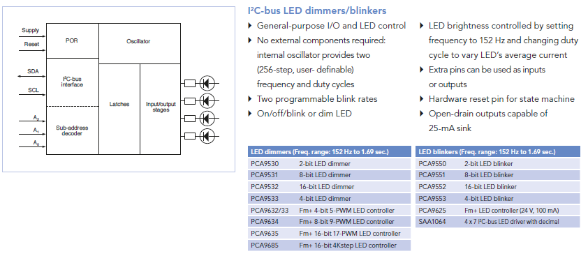
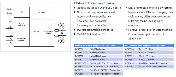
Blockschaltbild und Übersicht I2C-Bus LED Dimmer
-bit LED dimmer PCA9632/33 Fm+ 4-bit 5-PWM LED controller PCA9634 Fm+ 8-bit 9-PWM LED controller PCA9635 Fm+ 16-bit 17-PWM LED controller PCA9685 Fm+ 16-bit 4Kstep LED controller LED blinkers (Freq. range: 152 Hz to 1.69 sec.) PCA9550 2-bit LED blinker PCA9551 8-bit LED blinker PCA9552 16-bit LED blinker
in „Ansteuerung einer Anzeigetafel - Federal Vama Traffic Storm“ · Fahrzeugelektronik · · Diagramme
-
PDF
PCA9685.pdf
delay is independently programmable for each of the 16 channels. This feature is not available in PCA9635. • The PCA9685 has 4096 steps (12-bit PWM) of individual LED brightness control. The PCA9635 has only 256 steps (8-bit PWM). • When multiple LED controllers are incorporated in a system, the PWM pulse
in „LED-Streifen dimmen“ · Mikrocontroller und Digitale Elektronik ·
-
PDF
PCA9626.pdf
device registers to the same condition. In addition to these features found in PCA9633, PCA9634, PCA9635, PCA9622 and PCA9624, a new feature to control LED output pattern is incorporated in the PCA9626. A new control byte called ÔChase ByteÕ allows enabling or disabling of selective LED outputs depending
in „Probleme mit PCA9626 und I2C“ · Mikrocontroller und Digitale Elektronik ·
-
PDF
PCA9622DR_118.pdf
and quick way to reconfigure all device registers to the same condition. The PCA9622, PCA9625 and PCA9635 software is identical and if the PCA9622 on-chip 100 mA NAND FETs do not provide enough current or voltage to drive the LEDs, then the PCA9635 with larger current or higher voltage external drivers
in „Kontrolle Eagle Schaltplan“ · Mikrocontroller und Digitale Elektronik ·