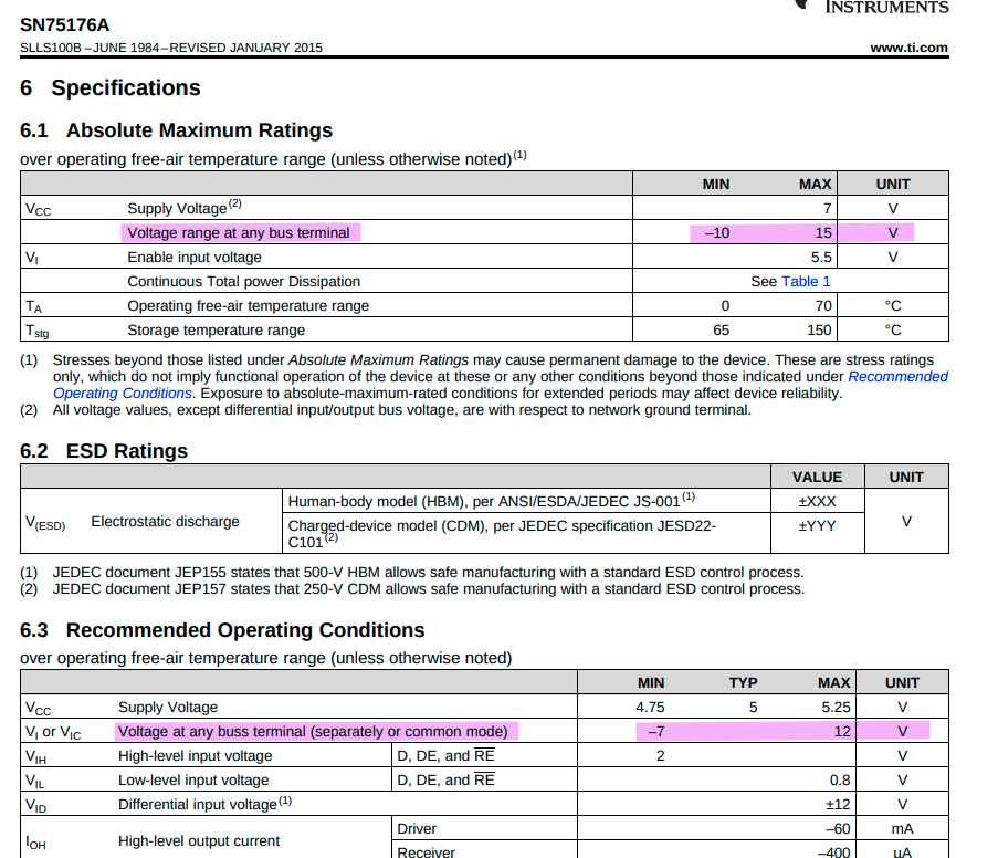
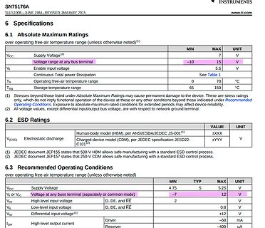
60 Low-level output curreOL, I mA Receiver 8 SN65176B –40 105 Operating free-air temperatAre, T SN75176B 0 70 ⋅C NOTE 2: Differential-input/output bus voltage is measured at the noninverting terminal A with respect to the inverting terminal B. 4 POST OFFICE BOX 6553DALLAS, TEXAS 75265 SN65176B, SN75176B
60 Low-level output curreOL, I mA Receiver 8 SN65176B –40 105 Operating free-air temperatAre, T SN75176B 0 70 ⋅C NOTE 2: Differential-input/output bus voltage is measured at the noninverting terminal A with respect to the inverting terminal B. 4 POST OFFICE BOX 6553DALLAS, TEXAS 75265 SN65176B, SN75176B
60 Low-level output curreOL, I mA Receiver 8 SN65176B –40 105 Operating free-air temperatAre, T SN75176B 0 70 ⋅C NOTE 2: Differential-input/output bus voltage is measured at the noninverting terminal A with respect to the inverting terminal B. 4 POST OFFICE BOX 6553DALLAS, TEXAS 75265 SN65176B, SN75176B
Driver 60 Low-level output currOLt, I mA Receiver 8 SN65176B –40 105 Operatingfree-air tempera, A ⋅C SN75176B 0 70 NOTE 3: Differential-input/output bus voltage is measured at the noninverting terminal A with respect to the inverting terminal B. POST OFFICE BOX 6553DALLAS, TEXAS 75265 3 SN65176B, SN75176B
Driver 60 Low-level output currOLt, I mA Receiver 8 SN65176B –40 105 Operatingfree-air tempera, A ⋅C SN75176B 0 70 NOTE 3: Differential-input/output bus voltage is measured at the noninverting terminal A with respect to the inverting terminal B. POST OFFICE BOX 6553DALLAS, TEXAS 75265 3 SN65176B, SN75176B
SN75176A DIFFERENTIAL BUS TRANSCEIVER SLLS100A – JUNE 1984 – REVISED MAY 1995 D Bidirectional Transceiver D OR P PACKAGE D Meets or Exceeds the Requirements of (TOP VIEW) ANSI Standards EIA/TIA-422-B and
SN65176B, SN75176B
SLLS101I – JULY 1985 – REVISED AUGUST 2025
Texas Instruments
www.ti.com
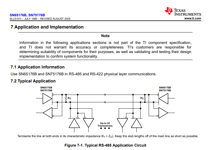
7 Application and Implementation
Note
7.1 Application Information
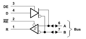
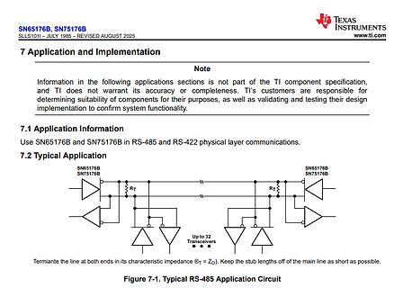
Use SN65176B and SN75176B in RS-485 and RS-422 physical layer communications.
7.2 Typical Application
SN65176B
SN75176B
RT
RT
Up to 32 Transceivers
Figure 7-1. Typical RS-485 Application Circuit
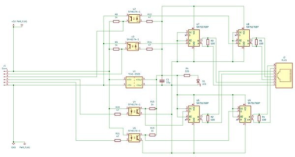
Receiver Transmitter) devices. These in tern drive industry standard RS485 line drivers based on the SN75176 device format. The actual device fitted may vary and may be replaced to suit you own requirements. (Driver voltage, unit load, current consumption etc.) Both MAX3100’s are driven from a single 3.6864MHz
~ 2 G D M 6 F 2 ~ C 1 T T1 BC547A IC4 VCC R . A DE O GND D - 1 SN75176BP R C1 T P A - H C e - FC3 1 M I 7 Q 8 D - IC3 C 4N33 E NC C K B A IC6 C7 100NF N 8 0 C 1 ~ BR1 D3 D1 - + D4 D2 F F F Maßstab 101,34% Firma Zeichner Blatt B380R 4 µ 5 µ 6 N ~ C+ 1 C + 1 C 1 Änderung12.05.09
Twisted-Pair Cable (Belden Reference Type 8205) 100 ns/Div 500 Meters Doubly Terminated With 100 SN75176B-Type Transceiver at Both Ends 50% Jitter Figure 5. 485 Signal Distortion vs Signaling Rate Fault Protection and Fail-Safe Operation Fault Protection — As with any system design, consideration should
/UCSRC|=(1<<USBS); //USBS0 2 Stop bits (this is for Attiny2313) DDRC |= 0xff; /*---Important for SN75176 / MAX485---*/ //Pin 2 and 3 must be set to LOW to receive data DDRD |= (1<<PD2); //Port as Output PORTD &= ~(1<<PD2); //Port to LOW /*---We put TIMER1 into Clear to Compare for PWM---*/ OCR1A = 512
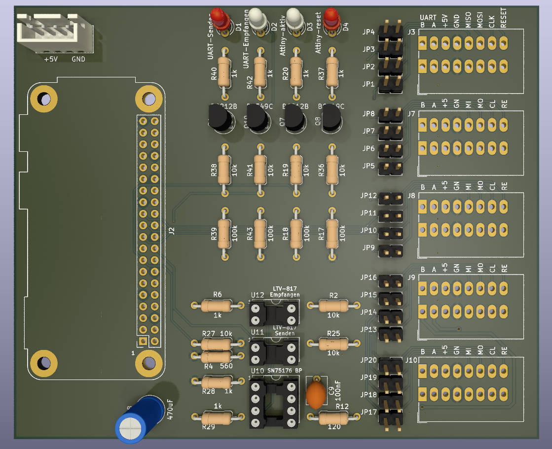
häufigsten verwendeten RS485 Treiber sind der MAX485 von Maxim, der LTC485 von Linear Technology und der SN75176 von Texas Instruments Alle diese Treiber sind zueinander Pin− und Funktionskompatibel, unterscheiden sich jedoch in der maximalen Datenrate und der Anzahl der Teilnehmer auf einem Bus. Je nach Ausführung
häufigsten verwendeten RS485 Treiber sind der MAX485 von Maxim, der LTC485 von Linear Technology und der SN75176 von Texas Instruments Alle diese Treiber sind zueinander Pin− und Funktionskompatibel, unterscheiden sich jedoch in der maximalen Datenrate und der Anzahl der Teilnehmer auf einem Bus. Je nach Ausführung
häufigsten verwendeten RS485 Treiber sind der MAX485 von Maxim, der LTC485 von Linear Technology und der SN75176 von Texas Instruments Alle diese Treiber sind zueinander Pin− und Funktionskompatibel, unterscheiden sich jedoch in der maximalen Datenrate und der Anzahl der Teilnehmer auf einem Bus. Je nach Ausführung
häufigsten verwendeten RS485 Treiber sind der MAX485 von Maxim, der LTC485 von Linear Technology und der SN75176 von Texas Instruments Alle diese Treiber sind zueinander Pin− und Funktionskompatibel, unterscheiden sich jedoch in der maximalen Datenrate und der Anzahl der Teilnehmer auf einem Bus. Je nach Ausführung
Command Bargraph send continous #AQ 2#TS/#TR new firmware New addressable 2-wire RS485 Interface with SN75176 07.04.05 V1.3 New Commands #AG, #SI, #KAesses new firmware 13.05.05 V1.4 Bugfix in SPI- I2C-Mode after wrong Packet (NAK) new firmware T c n s h INHALT Ä d ALLGEMEINES.............................
18.01.05 V1.2 New Command Bargraph send continous #AQ 2 New addressable 2-wire RS485 Interface with SN75176 07.04.05 V1.3 New 32 additional I2C Addresses new firmware New Commands #AG, #SI, #KA 13.05.05 V1.4 Bugfix in SPI- I2C-Mode after wrong Packet (NAK) new firmware some problems with opertating >60°
Command Bargraph send continous #AQ 2#TS/#TR new firmware New addressable 2-wire RS485 Interface with SN75176 07.04.05 V1.3 New Commands #AG, #SI, #KAesses new firmware 13.05.05 V1.4 Bugfix in SPI- I2C-Mode after wrong Packet (NAK) new firmware T c n s h INHALT Ä d ALLGEMEINES.............................
18.01.05 V1.2 New Command Bargraph send continous #AQ 2 New addressable 2-wire RS485 Interface with SN75176 07.04.05 V1.3 New 32 additional I2C Addresses new firmware New Commands #AG, #SI, #KA 13.05.05 V1.4 Bugfix in SPI- I2C-Mode after wrong Packet (NAK) new firmware some problems with opertating >60°
erforderlich. Applikationsbeispiel APPLIKATIONSBEISPIEL:RS-485INTERFACE Mit einem externen Umsetzer (z.B. SN75176) kann das eDIP an einen 2-Draht RS-485 Bus angeschlossen werden. Somit können grosse Entfernungen bis zu 1200m (Ferndisplay) realisiert werden. Betrieb von mehreren EA eDIPs an einem RS-485 Bus durch
erforderlich. Applikationsbeispiel APPLIKATIONSBEISPIEL:RS-485INTERFACE Mit einem externen Umsetzer (z.B. SN75176) kann das eDIP an einen 2-Draht RS-485 Bus angeschlossen werden. Somit können grosse Entfernungen bis zu 1200m (Ferndisplay) realisiert werden. Betrieb von mehreren EA eDIPs an einem RS-485 Bus durch
8 und 9). 1 0 1 38400 0 1 1 57600 1 1 1 115200 RS-485INTERFACE Mit einem externen Umsetzer (z.B. SN75176) kann das EA eDIP320 an einen 2-Draht RS-485 Bus angeschlossen werden. Somit können grosse Entfernungen bis zu 1200m (Ferndisplay) realisiert werden. Betrieb von mehreren EA eDIP320 an einem RS-485
und 11). 0 1 1 57600 1 1 1 115200 0 0 0 230400 RS-485 INTERFACE Mit einem externen Umsetzer (z.B. SN75176) kann das eDIP an einen 2-Draht RS-485 Bus angeschlossen werden. Somit können grosse Entfernungen bis zu 1200m (Ferndisplay) realisiert werden. Betrieb von mehreren EA eDIPs an einem RS-485 Bus durch
is needed. Application note APPLICATIONEXAMPLE:RS-485INTERFACE With an external converter (e.g. SN75176), the EA eDIP can be connected to a 2-wire RS-485 bus. Large distances of up to 1200 m can thus be implemented (remote display). Several EA eDIP displays can be operated on a single RS-485 bus by
erforderlich. Applikationsbeispiel APPLIKATIONSBEISPIEL: RS-485 INTERFACE Mit einem externen Umsetzer (z.B. SN75176) kann das eDIP an einen 2-Draht RS-485 Bus angeschlossen werden. Somit können grosse Entfernungen bis zu 1200m (Ferndisplay) rea- lisiert werden.Betrieb von meh- reren EA eDIPs an einem RS- 485 Bus
erforderlich. Applikationsbeispiel APPLIKATIONSBEISPIEL: RS-485 INTERFACE Mit einem externen Umsetzer (z.B. SN75176) kann das eDIP an einen 2-Draht RS-485 Bus angeschlossen werden. Somit können grosse Entfernungen bis zu 1200m (Ferndisplay) realisiert werden. Betrieb von mehreren EA eDIPs an einem RS-485 Bus durch
erforderlich. Applikationsbeispiel APPLIKATIONSBEISPIEL: RS-485 INTERFACE Mit einem externen Umsetzer (z.B. SN75176) kann das eDIP an einen 2-Draht RS-485 Bus angeschlossen werden. Somit können grosse Entfernungen bis zu 1200m (Ferndisplay) realisiert werden. Betrieb von mehreren EA eDIPs an einem RS-485 Bus durch

 Bild
Bild
 Bild
Bild
 Bild
Bild
 Bild
Bild
 Bild
Bild
 Bild
Bild
 Bild
Bild
 Bild
Bild