-
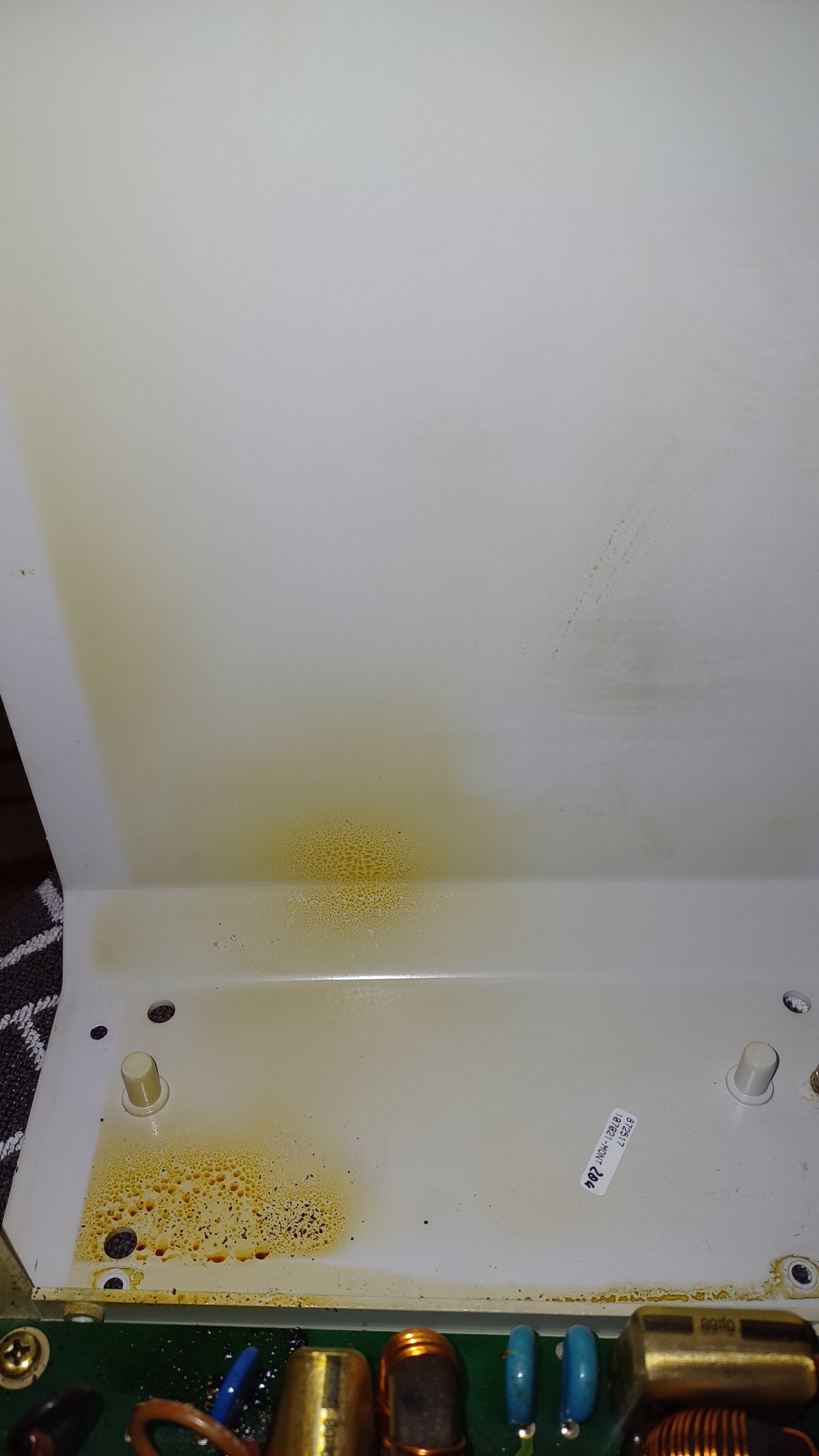
 Bild
Bild
-
 Bild
Bild
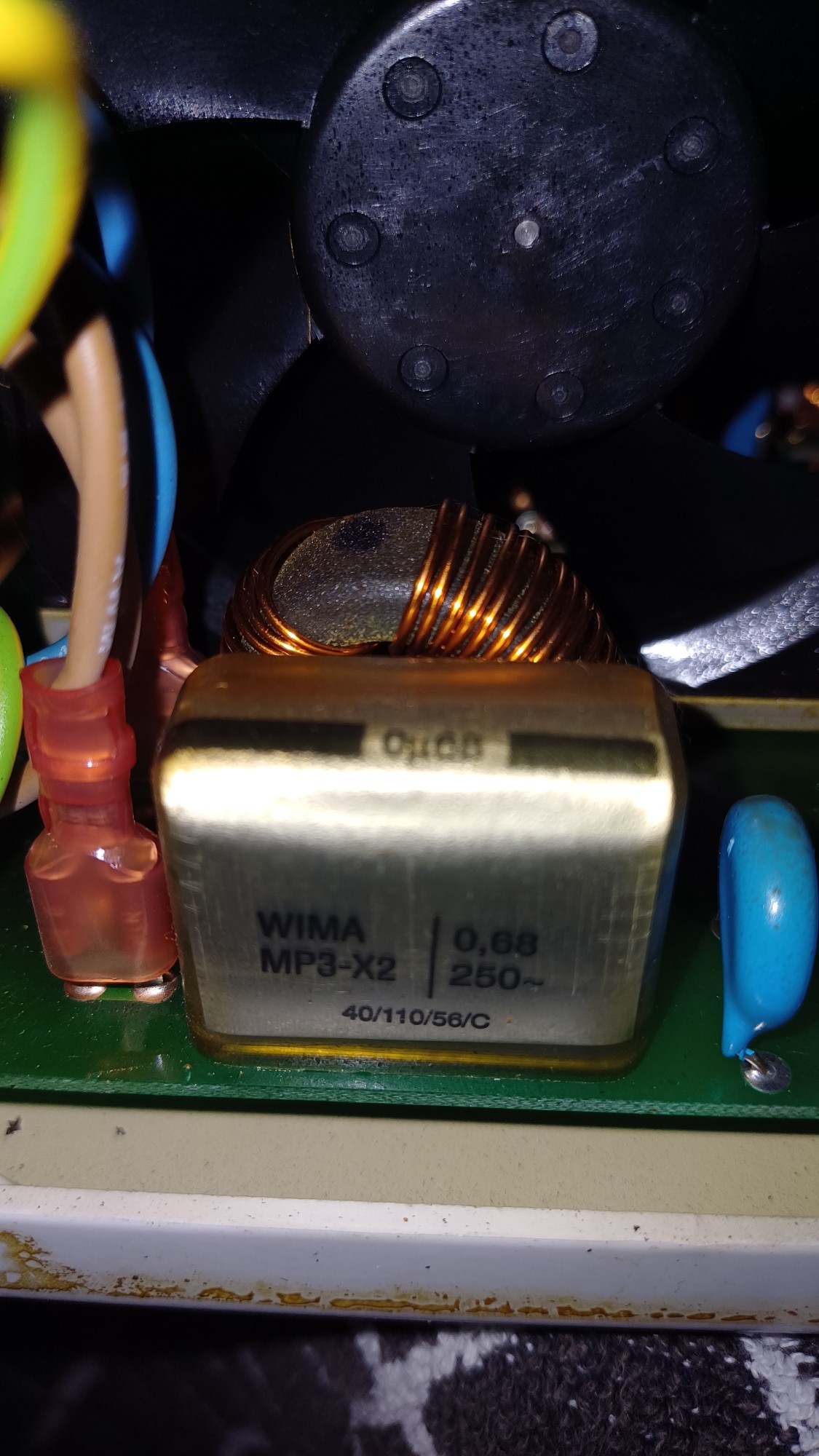
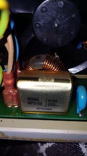
WIMA Entstörkondensator auf Leiterplatte
WIMA MP3-X2 0,68 250~ 40/110/56/C
in „Reparatur Ladegerät DBL430-14 Überspannung“ · Analoge Elektronik und Schaltungstechnik · · Platinenfotos
-
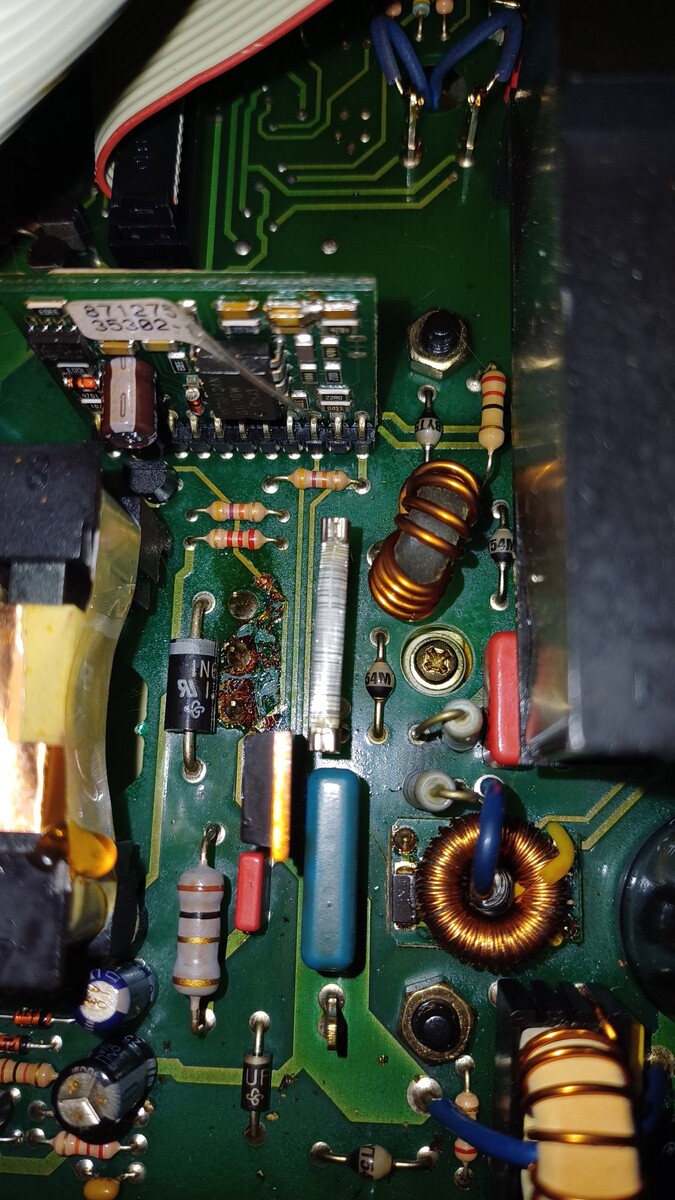
 Bild
Bild
-
Datei
stm32f4_discovery_lcd.c
0x0000,0x4100,0x2200,0x2200,0x1400,0x0800,0x0800,0x0800,0x0800,0x0800,0x0000,0x0000, 0x0000,0x7e00,0x0200,0x0400,0x0800,0x1000,0x1000,0x2000,0x4000,0x7e00,0x0000,0x0000, 0x0000,0x3000,0x2000,0x2000,0x2000,0x2000,0x2000,0x2000,0x2000,0x2000,0x2000,0x2000, 0x0000,0x4000,0x4000,0x2000,0x2000,0x2000,0x2000,0x2000,0x1000,0x1000,0x0000,0x0000
in „STM32F4Discovery mit CooCox CoOS-RTOS und printf“ · Projekte & Code ·
-
Datei
flashModi.txt
Flash Updater Sep 4 2006 22:24:20 [usbmsc.c:GetBotMaxBlockSize] Using MaxBlockSize 0x10000 (default 0x2000) USBMSC: Compiled Sep 4 2006 22:23:15 USBMSC: Modified, using block size = 0x10000 LcdInit ERROR: LCD not busy Storage devices: \USBDisk Key = mode, value = 0x00000002 INFO: Flashing the requested
in „Pollin - Receiver-Mainboard mit Twin DVB-[T,C] Tuner, NXP PNX8950EH“ · Mikrocontroller und Digitale Elektronik ·
-
PDF
TBS2000_vs__Keysight_X2000_3GW-60796-0.pdf
TBS2000 Series vs. Keysight X2000 Series COMPETITIVE FACT SHEET Visualization Probes and Measurements Tektronix TBS2000 Series Keysight X2000 Series Tektronix TBS2000 Series Keysight X2000 Series 9” WVGA display with 15 horizontal
in „Kaufentscheidung Oszilloskop“ · Mikrocontroller und Digitale Elektronik ·
-
Datei
double64-1.diff
, 1, 1, 0, 0x2000, 0, 0, "105", "avrxmega5" }, - { 0, 1, 1, 1, 1, 1, 1, 1, 0, 0, 0x2000, 0, 0, "106", "avrxmega6" }, - { 0, 1, 1, 1, 1, 1, 1, 1, 1, 0, 0x2000, 0, 0, "107", "avrxmega7" } + { 0, 0, 0, 0, 0, 0, 0, 0, 0
in „64 Bit float Emulator in C, IEEE754 compatibel“ · Projekte & Code ·
-
Datei
rc5.c
kopie_pinb==1) { empfangsfach=empfangsfach*2; empfangsfach|=1; } goto anfang; } } if((empfangsfach&0x2000)==0x2000) { return (empfangsfach); } else { return 0; } } /************************************************************************** * Initialisierung des Empfangsports: * *Diese Funktion initialisiert
in „Verwendung einer .h und .c; AVR“ · Mikrocontroller und Digitale Elektronik ·
-
Datei
test.asm
0x17 .equ MODE_UND, 0x1B .equ MODE_SYS, 0x1F .equ I_BIT, 0x80 .equ F_BIT, 0x40 .equ USR_STACK_SIZE, 0x2000 .equ FIQ_STACK_SIZE, 0x2000 .equ IRQ_STACK_SIZE, 0x2000 .equ SVC_STACK_SIZE, 0x2000 .equ ABT_STACK_SIZE, 0x2000 .equ UND_STACK_SIZE, 0x2000 .equ SYS_STACK_SIZE, 0x2000 .equ STACK_TOP, 0x4000F000 .equ
in „Funktion aus Interrupt aufrufen“ · Mikrocontroller und Digitale Elektronik ·
-
Datei
Interrupts.c
= delay_Sek_013) { delay_Sek_status_2 |= 0x1000; delay_Sek_status_1 &= ~0x1000; } break; // case 0x2000 : if(Timercounter_Sek == delay_Sek_014) { delay_Sek_status_2 |= 0x2000; delay_Sek_status_1 &= ~0x2000; } break; // case 0x4000 : if(Timercounter_Sek == delay_Sek_015) { delay_Sek_status_2 |= 0x4000
in „Zeitgesteuerter Ablauf mittels einer "State Mashine"“ · Mikrocontroller und Digitale Elektronik ·
-
Datei
objdump.txt
: f2c2 0300 movt r3, #8192 ; 0x2000 80002e4: 781b ldrb r3, [r3, #0] 80002e6: 461a mov r2, r3 80002e8: f240 4340 movw r3, #1088 ; 0x440 80002ec: f2c2 0300 movt r3, #8192 ; 0x2000 80002f0: f04f 0100 mov.w r1, #0 80002f4: 5499 strb r1,
in „STM32F4 HardFault Interrupt bei stdlib Funktionen“ · Mikrocontroller und Digitale Elektronik ·
-
Datei
NXP_emWinBSP_EA1788_Xpresso510_mem.ld
ORIGIN = 0x10000000, LENGTH = 0x10000 /* 64k */ RamAHB8_B0A (rwx) : ORIGIN = 0x20000000, LENGTH = 0x2000 /* 8k */ RamAHB8_B0B (rwx) : ORIGIN = 0x20020000, LENGTH = 0x2000 /* 8k */ RamAHB16_B1 (rwx) : ORIGIN = 0x20040000, LENGTH = 0x4000 /* 16k */ SDRAM32 (rwx) : ORIGIN = 0xA0000000, LENGTH = 0x02000000
in „LPC1857 ARM Cortex M3 Problem mit EMC und SDRAM“ · Mikrocontroller und Digitale Elektronik ·
-
Datei
lcd_fonts.c
, 0x0000, 0x0000, 0x0000, 0x0000, 0x0000, // ' 0x0800, 0x1000, 0x2000, 0x2000, 0x2000, 0x2000, 0x2000, 0x2000, 0x1000, 0x0800, // ( 0x2000, 0x1000, 0x0800, 0x0800, 0x0800, 0x0800, 0x0800, 0x0800, 0x1000, 0x2000, // ) 0x1000, 0x3800, 0x1000, 0x2800, 0x0000, 0x0000, 0x0000
in „Basteltip: STM32F103 DIP40 Board“ · Mikrocontroller und Digitale Elektronik ·
-
Datei
lcd_fonts.c
, 0x0000, 0x0000, 0x0000, 0x0000, 0x0000, // ' 0x0800, 0x1000, 0x2000, 0x2000, 0x2000, 0x2000, 0x2000, 0x2000, 0x1000, 0x0800, // ( 0x2000, 0x1000, 0x0800, 0x0800, 0x0800, 0x0800, 0x0800, 0x0800, 0x1000, 0x2000, // ) 0x1000, 0x3800, 0x1000, 0x2800, 0x0000, 0x0000, 0x0000
in „Lebensdauer von lokalen Variablen“ · Softwareentwicklung ·
-
Datei
lcd_fonts.c
, 0x0000, 0x0000, 0x0000, 0x0000, 0x0000, // ' 0x0800, 0x1000, 0x2000, 0x2000, 0x2000, 0x2000, 0x2000, 0x2000, 0x1000, 0x0800, // ( 0x2000, 0x1000, 0x0800, 0x0800, 0x0800, 0x0800, 0x0800, 0x0800, 0x1000, 0x2000, // ) 0x1000, 0x3800, 0x1000, 0x2800, 0x0000, 0x0000, 0x0000
in „DHT22 Feuchte Sensor ständig im Eimer“ · Mikrocontroller und Digitale Elektronik ·
-
Datei
MICforum.ino
Analog Devices UpdateRegister(0x50C7); UpdateRegister(0x4000); UpdateRegister(0xC000); UpdateRegister(0x2000); UpdateFreq(freq, 0x2000); // Sinus 1000 Hz freq=1; Timer1.initialize(alle_x_sekunden*100000); //Normal 1.000.000 Timer1.attachInterrupt(Frequenzzahlen); } void Frequenzzahlen(){ if(freq>99){ ser = 'e'; } if(ser == 's'){ freq+=1; UpdateFreq(freq, 0x2000); } if(ser == 'e'){ ser = 'w'; freq=1; UpdateFreq(0, 0x2000); } } void loop() { Start = digitalRead(Taster); if(Start == 1) { Start = 0; ser = 's'; digitalWrite(LED, HIGH); } if(Start == 0){ digitalWrite
in „Sweep Generator mit AD5930“ · Mikrocontroller und Digitale Elektronik ·
-
Datei
AD9833.ino
Analog Devices UpdateRegister(0x50C7); UpdateRegister(0x4000); UpdateRegister(0xC000); UpdateRegister(0x2000); UpdateFreq(freq, 0x2000); // Sinus 1000 Hz freq=1; Timer1.initialize(alle_x_sekunden*100000); //Normal 1.000.000 Timer1.attachInterrupt(Frequenzzahlen); } void Frequenzzahlen(){ if(freq>99){ ser = 'e'; } if(ser == 's'){ freq+=1; UpdateFreq(freq, 0x2000); } if(ser == 'e'){ ser = 'w'; freq=1; UpdateFreq(0, 0x2000); } } void loop() { Start = digitalRead(Taster); if(Start == 1) { Start = 0; ser = 's'; digitalWrite(LED, HIGH); } if(Start == 0){ digitalWrite
in „Sweep Generator mit AD5930“ · Mikrocontroller und Digitale Elektronik ·
-
Datei
anders.txt
format)") return "".join(bin) # in chip_m2764a.py def writeEEPROM(self, image): # if len(image) != 0x2000: # self.throwError("Invalid EPROM image size %d (expected %d)" %\ # (len(image), 0x2000)) self.top.cmdSetVCCXVoltage(5) self.top.cmdSetVPPVoltage(12) self.top.vccx.setLayoutPins( (38,) ) self.top.vpp.setLayoutPins( (5, 6, 7, 9, 11) ) self.top.gnd.setLayoutPins( (24,) ) self.progressMeterInit("Writing EPROM", 0x2000) self.__setEG(E=1, G=1) for addr in range(0, 0x2000): self.progressMeter(addr) if ord(image[addr]) != 0xFF: self.__writeData(addr, ord(image[addr])) self.__setEG(E=1, G=1) self.progressMeterFinish(
in „TOP2049 programmer opensource software“ · Mikrocontroller und Digitale Elektronik ·
-
Datei
msp430x20x2.h
0x800u) /* 16 x ADC10CLKs */ #define ADC10SHT_3 (3*0x800u) /* 64 x ADC10CLKs */ #define SREF_0 (0*0x2000u) /* VR+ = AVCC and VR- = AVSS */ #define SREF_1 (1*0x2000u) /* VR+ = VREF+ and VR- = AVSS */ #define SREF_2 (2*0x2000u) /* VR+ = VEREF+ and VR- = AVSS */ #define SREF_3 (3*0x2000u) /* VR+ = VEREF+ and VR- = AVSS */ #define SREF_4 (4*0x2000u) /* VR+ = AVCC and VR- = VREF-/VEREF- */ #define SREF_5 (5*0x2000u) /* VR+ = VREF+ and VR- = VREF-/VEREF- */ #define SREF_6 (6*0x2000u) /* VR+ = VEREF+ and VR- = VREF-/VEREF- */ #define SREF_7 (7*
in „msp430x20x2.h gesucht“ · Mikrocontroller und Digitale Elektronik ·
-
Datei
ld_script.ld
ORIGIN = 0x10000000, LENGTH = 0x10000 /* 64k */ RamAHB8_B0A (rwx) : ORIGIN = 0x20000000, LENGTH = 0x2000 /* 8k */ RamAHB8_B0B (rwx) : ORIGIN = 0x20020000, LENGTH = 0x2000 /* 8k */ RamAHB16_B1 (rwx) : ORIGIN = 0x20040000, LENGTH = 0x4000 /* 16k */ } /* Define a symbol for the top of each memory region
in „LPC1788 - startup / .ld-script“ · Mikrocontroller und Digitale Elektronik ·
-
 Bild
Bild
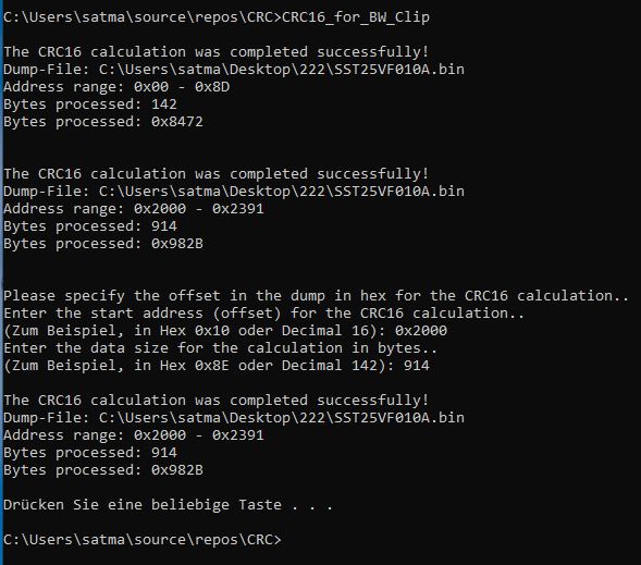
Konsole mit CRC16-Berechnungsergebnissen
0x10 oder Decimal 16): 0x2000 Enter the data size for the calculation in bytes.. (Zum Beispiel, in Hex 0x8E oder Decimal 142): 914 The CRC16 calculation was completed successfully! Dump-File: C:\Users\satma\Desktop\222\SST25VF010A.bin Address range: 0x2000 - 0x2391 Bytes processed: 914 Bytes processed: 0x982B Drücken Sie eine beliebige Taste . . . C:\Users\satma\source\repos\CRC>
in „Reset BW Clip“ · Mikrocontroller und Digitale Elektronik · · Screenshots

-
Datei
definitions.h
MHz liegen) #define MSEL (PLL_M-1) #define VPBDIV_VAL 4 // Peripherie #define LED_GRN_ON (IO0CLR = 0x2000) // Einschalten der grünen LED auf Olimex #define LED_GRN_OFF (IO0SET = 0x2000) // Ausschalten... #define LED_ROT_ON (IO0CLR = 0x1000) // Einschalten der roten LED auf Olimex #define LED_ROT_OFF (IO0SET = 0x1000) // dito #define LED_GRN_BIT 13 //#define LED_GRN_MASK 0x2000 #define LED_ROT_BIT 12 //#define LED_ROT_MASK 0x1000 #endif
in „Einsteigerproblem LPC1227“ · Mikrocontroller und Digitale Elektronik ·
-
Datei
vs1011.h
0x3009, 0x2741, 0x36f3, 0xd80e, 0x36f1, 0xd813, 0x36f1, 0x5806, 0x36f0, 0x9803, 0x36f0, 0x1801, 0x2000, 0x0000, 0x36f2, 0x9814, 0x81f9, 0x4c82, 0x0024, 0x0000, 0x0024, 0x2000, 0x0005, 0xf5c2, 0x0024, 0x0000, 0x0980, 0x2000, 0x0000, 0x6010, 0x0024, 0x8200, 0x4080, 0x184c, 0x3e03, 0x784f, 0x2800, 0x8205
in „VS1011 an PIC18F252 Audio-Probleme“ · Mikrocontroller und Digitale Elektronik ·
-
Datei
msp430f149.h
Counter lenght: 10 bit */ #define CNTL_3 (3*0x0800u) /* Counter lenght: 8 bit */ #define SHR_0 (0*0x2000u) /* Timer B Group: 0 - individually */ #define SHR_1 (1*0x2000u) /* Timer B Group: 1 - 3 groups (1-2, 3-4, 5-6) */ #define SHR_2 (2*0x2000u) /* Timer B Group: 2 - 2 groups (1-3, 4-6)*/ #define SHR_3 (3*0x2000u) /* Timer B Group: 3 - 1 group (all) */ #define TBCLGRP_0 (0*0x2000u) /* Timer B Group: 0 - individually */ #define TBCLGRP_1 (1*0x2000u) /* Timer B Group: 1 - 3 groups (1-2, 3-4, 5-6) */ #define
in „MSP430 Portfehler“ · Mikrocontroller und Digitale Elektronik ·
-
Datei
Open_On-Chip_Debugger_0.3.1-snapshot__256_K.txt
halted target halted due to debug-request, current mode: Thread xPSR: 0x01000000 pc: 0x00000a98 msp: 0x2000fffc requesting target halt and executing a soft reset target state: halted target halted due to debug-request, current mode: Thread xPSR: 0x01000000 pc: 0x00000a98 msp: 0x2000fffc Info : device id
in „STM32 hat zu wenig Flash?“ · Mikrocontroller und Digitale Elektronik ·
-
 Bild
Bild
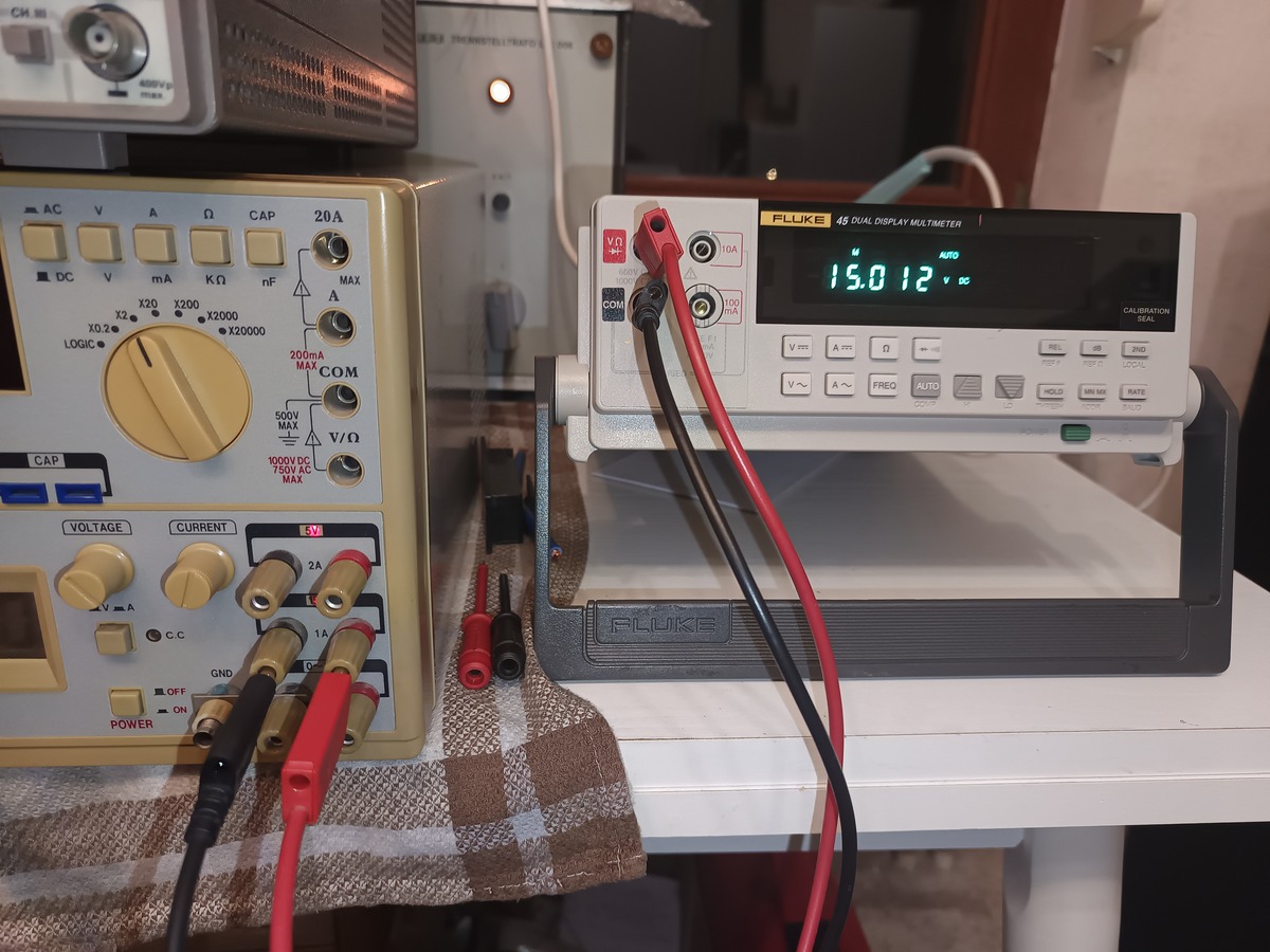
Fluke Multimeter und Netzteil auf Arbeitstisch
400Vp max, AC, V, Ω, CAP, 20A, MAX, DC, mA, KΩ, nF, X2, X20, X2000, X2000, LOGIC, 200mA, COM, 500V MAX, V/Ω, VOLTAGE, CURRENT, V, A, C.C, GND, 2A, 1A, OFF, ON, POWER, FLUKE 45 DUAL DISPLAY MULTIMETER, AUTO, 15.012 V, COM, V m, A mm, Ω, REL, dB, ZERO, V ~, FREQ, AUTO
in „[V] Metex MS-9140 Universal System“ · Markt · · Fotos
-
Datei
testimg.c
0x9A19,0x3719,0x3619,0x3619,0xF418,0xF108,0xCF08,0x8E10,0x8B00,0x6B00,0x6A00,0x6900,0x8700,0x6900,0x8808,0x4A08,0x6C08,0x6800,0x8D08,0x9108,0xB508,0x1911,0xB608,0x7000,0x4C00,0x4800,0x2C00,0x2900,0x2500,0x2700,0x2508,0x2608,0x4400,0x2400,0x2100,0x2400,0x2A00,0x2508,0x2500,0x4508,0x2708,0x2B08,0x2800,0x2200,0x2200,0x2000,0x2000,0x2000,0x2008,0x2000,0x4000,0x2000,0x2000,0x2000,0x4000,0x0308,0x2308,0x2100,0x4100,0x4300,0x6208,0x8310,0x8410,0xA508,0x8608,0x8A10,0xCE10,0x6B21,0xEA31,0x4A52,0xCA62,0x2B6B,0x4C73,0x6B73,0x6B73,0x6B6B
in „Image Converter - Bild zu c array konvertieren“ · Mikrocontroller und Digitale Elektronik ·
-
Datei
testimg.h
0x9A19,0x3719,0x3619,0x3619,0xF418,0xF108,0xCF08,0x8E10,0x8B00,0x6B00,0x6A00,0x6900,0x8700,0x6900,0x8808,0x4A08,0x6C08,0x6800,0x8D08,0x9108,0xB508,0x1911,0xB608,0x7000,0x4C00,0x4800,0x2C00,0x2900,0x2500,0x2700,0x2508,0x2608,0x4400,0x2400,0x2100,0x2400,0x2A00,0x2508,0x2500,0x4508,0x2708,0x2B08,0x2800,0x2200,0x2200,0x2000,0x2000,0x2000,0x2008,0x2000,0x4000,0x2000,0x2000,0x2000,0x4000,0x0308,0x2308,0x2100,0x4100,0x4300,0x6208,0x8310,0x8410,0xA508,0x8608,0x8A10,0xCE10,0x6B21,0xEA31,0x4A52,0xCA62,0x2B6B,0x4C73,0x6B73,0x6B73,0x6B6B
in „Image Converter - Bild zu c array konvertieren“ · Mikrocontroller und Digitale Elektronik ·
-
PDF
W2000L_reference_manual.pdf
LSB CH1 MSB CH1 LSB #0 #0 #0 #0 00 4 8 CH0 CH1 CH2 CH3 #0 #0 #0 #0 01 2 8 CH0 CH1 CH0 CH1 #0 #0 #0x2000 #0x2000 01 1 16 CH0 MSB CH0 LSB CH0 MSB CH0 LSB #0 #0 #0x2000 #0x2000 11 1 8 CH0 CH0 CH0 CH0 #0 #0x2000 #0x4000 #0x6000 5.2.9 trigger source reg @ 0x30 The trigger can only handle 8 bits and one channel
in „made from scratch Firmware für Wittig/Welec Oszilloskop W20xxA“ · Mikrocontroller und Digitale Elektronik ·
-
Datei
local.eagle.flash.ld
0x40300000 ); PROVIDE ( _FS_end = 0x405FA000 ); PROVIDE ( _FS_page = 0x100 ); PROVIDE ( _FS_block = 0x2000 ); PROVIDE ( _EEPROM_start = 0x405fb000 ); /* The following symbols are DEPRECATED and will be REMOVED in a future release */ PROVIDE ( _SPIFFS_start = 0x40300000 ); PROVIDE ( _SPIFFS_end = 0x405FA000 ); PROVIDE ( _SPIFFS_page = 0x100 ); PROVIDE ( _SPIFFS_block = 0x2000 ); INCLUDE "local.eagle.app.v6.common.ld"
in „Was ist die Block-Größe meines SPI-ROMs auf dem ESP8266?“ · Mikrocontroller und Digitale Elektronik ·
-
Datei
main.c
setPmtVoltage(uint16_t value){ for(uint8_t channelIdx = 0; channelIdx<2; channelIdx++){ uint16_t dacValue = 0x2000; //exclusively load a or b channel PORTBbits.RB6 = 0; //select desired DAC chip dacValue += ((uint16_t)channelIdx<<12); //select channel a=0 or channel b=1 if(channelIdx == 0){ //channel a dacValue
in „Pollin PMT-Modul“ · Mikrocontroller und Digitale Elektronik ·
-
Datei
io430x16x.h
_3 (3*0x2000u) /* Timer B Group: 3 - 1 group (all) */ #define TBCLGRP_0 (0*0x2000u) /* Timer B Group: 0 - individually */ #define TBCLGRP_1 (1*0x2000u) /* Timer B Group: 1 - 3 groups (1-2, 3-4, 5-6) */ #define
in „Pins ein und ausschalten“ · Mikrocontroller und Digitale Elektronik ·
-
Datei
Rc5dec.c51
if( rc5_busy == 0 ){ if( rc5_bit == 1 ){ // start pulse detect rc5_busy = 1; rc5_tmp = 1; // == 0x2000 after 13 shift } }else{ if( rc5_time > PULSE1_2 ) // if to short return; // then continue rc5_tmp <<= 1; // shift if( rc5_bit ) rc5_tmp |= 1; // add new bit if( rc5_tmp & 0x2000 ){ // after shifted
in „Delay im us-Bereich“ · Mikrocontroller und Digitale Elektronik ·
-
Datei
Rc5rec2.c51
if( rc5_busy == 0 ){ if( rc5_bit == 1 ){ // start pulse detect rc5_busy = 1; rc5_tmp = 1; // == 0x2000 after 13 shift } }else{ if( rc5_time > PULSE1_2 ) // if pulse to short return; // continue rc5_tmp <<= 1; // shift if( rc5_bit ) rc5_tmp |= 1; // add new bit if( rc5_tmp & 0x2000 ){ // after shifted
-
Datei
Rc5rec2.c51
if( rc5_busy == 0 ){ if( rc5_bit == 1 ){ // start pulse detect rc5_busy = 1; rc5_tmp = 1; // == 0x2000 after 13 shift } }else{ if( rc5_time > PULSE1_2 ) // if to short return; // then continue rc5_tmp <<= 1; // shift if( rc5_bit ) rc5_tmp |= 1; // add new bit if( rc5_tmp & 0x2000 ){ // after shifted
in „BI-Phase Codierung“ · Mikrocontroller und Digitale Elektronik ·
-
Datei
Rc5rec2.c51
if( rc5_busy == 0 ){ if( rc5_bit == 1 ){ // start pulse detect rc5_busy = 1; rc5_tmp = 1; // == 0x2000 after 13 shift } }else{ if( rc5_time > PULSE1_2 ) // if to short return; // then continue rc5_tmp <<= 1; // shift if( rc5_bit ) rc5_tmp |= 1; // add new bit if( rc5_tmp & 0x2000 ){ // after shifted
in „Manchester Code - wer kann mir mal helfen?“ · Mikrocontroller und Digitale Elektronik ·
-
Datei
Rc5dec.c51
if( rc5_busy == 0 ){ if( rc5_bit == 1 ){ // start pulse detect rc5_busy = 1; rc5_tmp = 1; // == 0x2000 after 13 shift } }else{ if( rc5_time > PULSE1_2 ) // if to short return; // then continue rc5_tmp <<= 1; // shift if( rc5_bit ) rc5_tmp |= 1; // add new bit if( rc5_tmp & 0x2000 ){ // after shifted
in „asm in c übersetzen...“ · Mikrocontroller und Digitale Elektronik ·
-
Datei
m2764a-optimize-read.patch
+0100 @@ -63,9 +63,15 @@ class M2764A(Chip): image = "" self.progressMeterInit("Reading EPROM", 0x2000) self.__setEG(E=1, G=1) + byteCount = 0 for addr in range(0, 0x2000): self.progressMeter(addr) - image += self.__readData(addr) + self.__readDataToStatusReg(addr) + byteCount += 1 + if byteCount ==
in „TOP2049 programmer opensource software“ · Mikrocontroller und Digitale Elektronik ·
-
Datei
RC5DEC.C51
if( rc5_busy == 0 ){ if( rc5_bit == 1 ){ // start pulse detect rc5_busy = 1; rc5_tmp = 1; // == 0x2000 after 13 shift } }else{ if( rc5_time > PULSE1_2 ) // if to short return; // then continue rc5_tmp <<= 1; // shift if( rc5_bit ) rc5_tmp |= 1; // add new bit if( rc5_tmp & 0x2000 ){ // after shifted
in „RC5-Code-Empfangsprogramm für 8051er in Assembler“ · Mikrocontroller und Digitale Elektronik ·
-
Datei
WAV-Player2.c
Mit Bin2Hex Name.wav Name.hex -o 2000 wird die Datei in eine HEX-Datei umgewandelt, die ab Adresse 0x2000 beginnt. HEX |DESCRIPTION 0000 |RIFF (in plain ASCII text) 0004 |Length of the entire file as a 32-bit unsigned integer 0008 |WAVE (in plain ASCII text) 000C |fmt[] (fmt[] in ASCII text denotes subchunk
in „8051 soll Sound rausschicken“ · Mikrocontroller und Digitale Elektronik ·
-
Datei
disassembly_Variante_Fehlerhaft.txt
6119 str r1, [r3, #16] GPIOA->BRR = GPIO_Pin_3; TimeTick++; 800011c: f2c2 0200 movt r2, #8192 ; 0x2000 void TIM3_IRQHandler(void) { //debugging: one high-pulse on GPIO A3 GPIOA->BSRR = GPIO_Pin_3; GPIOA->BRR = GPIO_Pin_3; 8000120: 6159 str r1, [r3, #20] TimeTick++; 8000122: 6811 ldr r1, [r2, #0] oneMsTick
in „STM32: Timer-ISR löst 2x aus - Fehler im Flag-Reset bei Optimierung O3“ · Mikrocontroller und Digitale Elektronik ·
-
Datei
disassembly_Variante_Workaround.txt
6111 str r1, [r2, #16] GPIOA->BRR = GPIO_Pin_3; TimeTick++; 800011c: f2c2 0300 movt r3, #8192 ; 0x2000 void TIM3_IRQHandler(void) { //debugging: one high-pulse on GPIO A3 GPIOA->BSRR = GPIO_Pin_3; GPIOA->BRR = GPIO_Pin_3; 8000120: 6151 str r1, [r2, #20] TimeTick++; 8000122: 6819 ldr r1, [r3, #0] oneMsTick
in „STM32: Timer-ISR löst 2x aus - Fehler im Flag-Reset bei Optimierung O3“ · Mikrocontroller und Digitale Elektronik ·
-
Datei
hw_define.h
////////// #define DELAY_TIMER_1MS 0x0400 #define DELAY_TIMER_4MS 0x1000 #define DELAY_TIMER_8MS 0x2000 #define DELAY_TIMER_10MS 0x2800 // TAR 0x0060 ~100µS (berechnet) // TAR 0x0100 ~150µS // TAR 0x0180 ~400µS (berechnet) // TAR 0x0300 ~800µS // TAR 0x0400 ~1mS // TAR 0x1000 ~4mS // TAR 0x2000 ~8mS
in „Pcitiva Oled 128x64“ · Mikrocontroller und Digitale Elektronik ·
-
Datei
memtest.c
#define MEM_WINDOW_LOCATION 0x4000 #define MEM_WINDOW_SIZE 0x2000 unsigned int start_address = 0; unsigned int end_address = 0x2000; void memtest(void) { unsigned long int mem_block; unsigned int address; unsigned int *ptr; // Initialise system map_4k(MMU_ADR(MEM_WINDOW_LOCATION
in „gcc variable placement“ · Mikrocontroller und Digitale Elektronik ·
-
Datei
Open_On-Chip_Debugger_0.3.1-snapshot__384_K.txt
halted target halted due to debug-request, current mode: Thread xPSR: 0x01000000 pc: 0x00000178 msp: 0x2000fffc requesting target halt and executing a soft reset target state: halted target halted due to debug-request, current mode: Thread xPSR: 0x01000000 pc: 0x00000178 msp: 0x2000fffc Info : device id
in „STM32 hat zu wenig Flash?“ · Mikrocontroller und Digitale Elektronik ·
-
Datei
FileTransfer.c
data BYTE M_State, BlockIndex, PageIndex, BlocksWrote, NumBlocks; __code const BYTE LengthFile[3] @ 0x2000; /*--[ USB Descriptor Information ]--------------------------------------------*/ __code const UINT USB_VID = 0x10C4; __code const UINT USB_PID = 0xEA61; __code const BYTE USB_MaxPower = 15; /* Max
in „Puffer-Problem mit C8051F320 (8051)“ · Mikrocontroller und Digitale Elektronik ·
-
Datei
logFile.txt
) ATI Technologies Inc unknown chipset (0x3150) rev 0, Mem @ 0xc0000000/27, 0xc8800000/16, I/O @ 0x2000/8 (II) Addressable bus resource ranges are [0] -1 0 0x00000000 - 0xffffffff (0x0) MX[B] [1] -1 0 0x00000000 - 0x0000ffff (0x10000) IX[B] (II) OS-reported resource ranges: [0] -1 0 0xffe00000 - 0xffffffff
-
Datei
Rc5.asm
_busy == 0 ){ ; if( rc5_bit == 1 ){ // start pulse detect ; rc5_busy = 1; ; rc5_tmp = 1; } // == 0x2000 after 13 shift ; }else{ ; if( rc5_time > PULSE1_2 ) // if pulse to short ; return; // continue ; rc5_tmp <<= 1; // shift ; if( rc5_bit ) ; rc5_tmp |= 1; // add new bit ; if( rc5_tmp & 0x2000 ){ //
-
Datei
rc5u.c
e++; //a <<= 1; //schieben //a <<= 1; //schieben //a|=1; }*/ } // if( !(tmp & 0x4000) && (tmp & 0x2000) ) // only if 14 bits received // wenn adresse von tmp ungleich 0x4000 und adresse von tmp gleich 0x2000 dann....
in „Problem mit Interrupt“ · Mikrocontroller und Digitale Elektronik ·
-
Datei
main.s
, = TIM2_SR MOV r1, #0 STR r1, [r0] ;Toggeln für PINC 13 LDR r0, = GPIOC_ODR MOV r1, #0 MOV r2, #0x2000 ;Vergleicht ob ODR für PINC13 gestzt ist oder nicht LDR r3, [r0] CMP r3, #0x2000 STREQ r1, [r0] STRNE r2, [r0] BX LR ENDP END
in „STM32 ASM Interrupt“ · Mikrocontroller und Digitale Elektronik ·