-
Bild
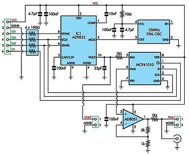
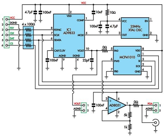
Schaltplan einer analogen Schaltung mit AD9833 und MCP41010
VCC, 4.7µF, 100nF, IC1 AD9833, 10Ω, 25MHz XTAL OSC, EN, VDD, COMP, FSYNC, CLK, SCLK, SDATA, CS, CAP/2.5V, MCLK, OUT, GND, 100nF, 4.7µF, 0Ω, MCP41010, VOUT, DGND, PA0, CS, 3, SI, SCK, PBO, 22pF, GND, 100nF, AD8051, VOUT, AGND,
in „AD9833 Modul mit MCP41010“ · Mikrocontroller und Digitale Elektronik · · Schaltpläne
-
Bild
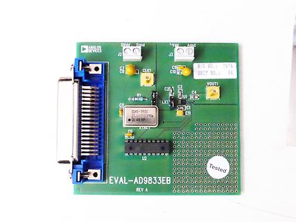
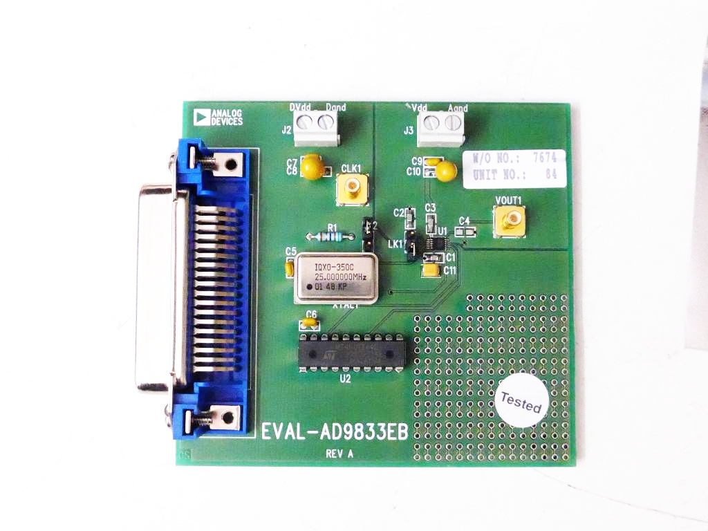
Analog Devices EVAL-AD9833EB Evaluation Board
C7 C8 CLK1 C9 C10 C2 C3 C4 VOUT1 LK1 U1 C1 C11 C5 IQXO-350C 25.000000MHZ 01 48 KP C6 U2 Tested EVAL-AD9833EB REV A
in „[V] AD9833-Eval-Kit; Programmable Waveform-Generator“ · Markt · · Platinenfotos
-
Bild
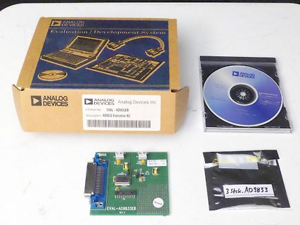
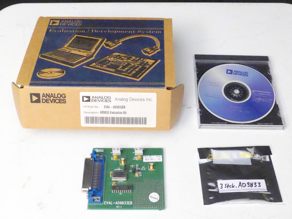
Analog Devices EVAL-AD9833 Evaluation Kit mit CD und Platine
ANALOG DEVICES Evaluation / Development System (1P) Part No EVAL-AD9833EB Description: AD9833 Evaluation Kit Analog Devices Inc. EVAL-AD9833EB REV A 3 stk. AD9833
in „[V] AD9833-Eval-Kit; Programmable Waveform-Generator“ · Markt · · Fotos
-
PDF
ad9833.pdf
the AD9833. falling SCLK edges occur in each cycle. To load the remaining AD9833 TO68HC11/68L11 INTERFACE eight bits to the AD9833, P3.3 is held low after the first eight Figure 29 shows the serial interface
in „Aus ca. 0,3V Wechselspannung (Sinus) 15 V Wechselspannung machen“ · Analoge Elektronik und Schaltungstechnik ·
-
PDF
AD9833.pdf
into the AD9833. Figure 10. ADSP-2101/ADSP-2103 to AD9833 Interface AD9833 to ADSP-21xx Interface AD9833 to 68HC11/68L11 Interface Figure 11 shows the serial interface between the AD9833 and Figure 10 shows the
-
Datei
DDS.c
= (dwCodeWord & 0x0FFFC000) >> 14; //msb wWord |= 0x4000; //set bit 15 DDS_WriteWord(wWord); } /* AD9833 to 80C51/80L51 Interface Figure 12 shows the serial interface between the AD9833 and the 80C51/80L51 microcontroller. The microcontroller is operated in mode 0 so that TXD of the 80C51/80L51 drives SCLK of the AD9833, while RXD drives the serial data line SDATA. The FSYNC signal is again derived from a bit programmable pin on the port (P3.3 being used in the diagram). When data is to be transmitted to the AD9833
-
Datei
DDS.c
wWord = (dwCodeWord & 0xFFFC000) >> 14; //msb wWord |= 0x4000; //set bit 15 DDS_WriteWord(wWord); } /* AD9833 to 80C51/80L51 Interface Figure 12 shows the serial interface between the AD9833 and the 80C51/80L51 microcontroller. The microcontroller is operated in mode 0 so that TXD of the 80C51/80L51 drives SCLK of the AD9833, while RXD drives the serial data line SDATA. The FSYNC signal is again derived from a bit programmable pin on the port (P3.3 being used in the diagram). When data is to be transmitted to the AD9833
in „Daten zum AD9833 in C übertragen“ · Mikrocontroller und Digitale Elektronik ·
-
Datei
ad9833_beispiel.asm
.include "m8def.inc" ;Dieses Programm zeigt ein Beispiel mit dem AD9833. ;Es kommuniziert mit dem AD9833 über SPI. ;Mit diesem Programm erzeugt der AD9833 ein Sinussignal ;mit einer Frequenz von 1kHz .org 0x00 rjmp reset .def temp = r16 .def s_data_low = r17 ;Serielle
in „Beispielprogramm AD9833 (DDS) mit atmega8“ · Projekte & Code ·
-
PDF
-
Datei
ad9833.txt
#include <p33FJ128MC706.h> #include <dsp.h> #include <libpic30.h> #include "..\h\manualSPI.h" void SPI3_send(int data) { int i; for(i=0;i<16;i++) { SPI3_OUT =((data >> i) & 0x01); delay_ms(10); SPI3_CLK = 1; delay_ms(10); SPI3_CLK = 0; //data >>= 1; } } void SPI3_start(void) { SPI3_CS = 1; delay_ms(10); SPI3_CLK = 1; delay_ms(10); SPI3_CS = 0; delay_ms(10); } void SPI3_end(void) { //delay_ms(10); SPI3_CS = 1; delay_ms(10); } void init_dds(void) { int data; TRISD = 0; data = 0x2108; // Reset registers SPI3_start(); SPI3_send(data); SPI3_end(); data = 0x75C3; // 14 LSB's of FREQ0 SPI3_start(); SPI3
in „ad9833 codefrage [not working]“ · Mikrocontroller und Digitale Elektronik ·
-
Datei
AD9833.ino
#include "Wire.h" #include "TimerOne.h" int FSYNC = 6; int SDATA = 7; int SCLK = 8; int LED = 3; int Taster = 2; int Start = 0; unsigned long erg; unsigned long freq=0; byte wave=1; char ser='w'; int alle_x_sekunden=1; int aktiv=1; void setup() { pinMode(LED, OUTPUT); pinMode(Taster, INPUT); pinMode(FSYNC, OUTPUT); pinMode(SDATA, OUTPUT); pinMode(SCLK, OUTPUT); digitalWrite(FSYNC, HIGH); digitalWrite(SDATA, LOW); digitalWrite(SCLK, HIGH); Wire.begin(); Serial.begin(38400); UpdateRegister(0x2100); // Nach Application Note AN-1070 von Analog Devices UpdateRegister(0x50C7); UpdateRegister(0x4000)
in „Sweep Generator mit AD5930“ · Mikrocontroller und Digitale Elektronik ·
-
Bild
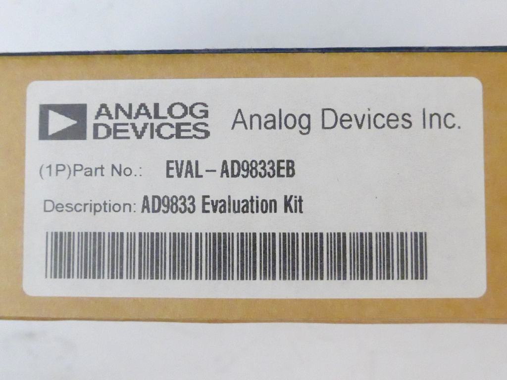
Etikett eines Analog Devices Evaluation Kits
ANALOG DEVICES Analog Devices Inc. (1P)Part No.: EVAL-AD9833EB Description: AD9833 Evaluation Kit
in „[V] AD9833-Eval-Kit; Programmable Waveform-Generator“ · Markt · · Fotos
-
Datei
sweep.ino
// for chip info see https://www.analog.com/en/products/ad9833.html // SPI code taken from https://github.com/MajicDesigns/MD_AD9833/ const uint8_t _dataPin = 7; const uint8_t _clkPin = 8; const uint8_t _fsyncPin = 6; // send raw 16-bit word void spiSend(const
in „Arduino+AD9833 code für Rechteckfestfrequenz“ · Mikrocontroller und Digitale Elektronik ·
-
Bild
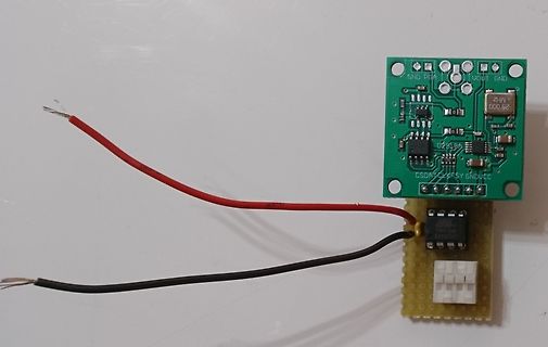
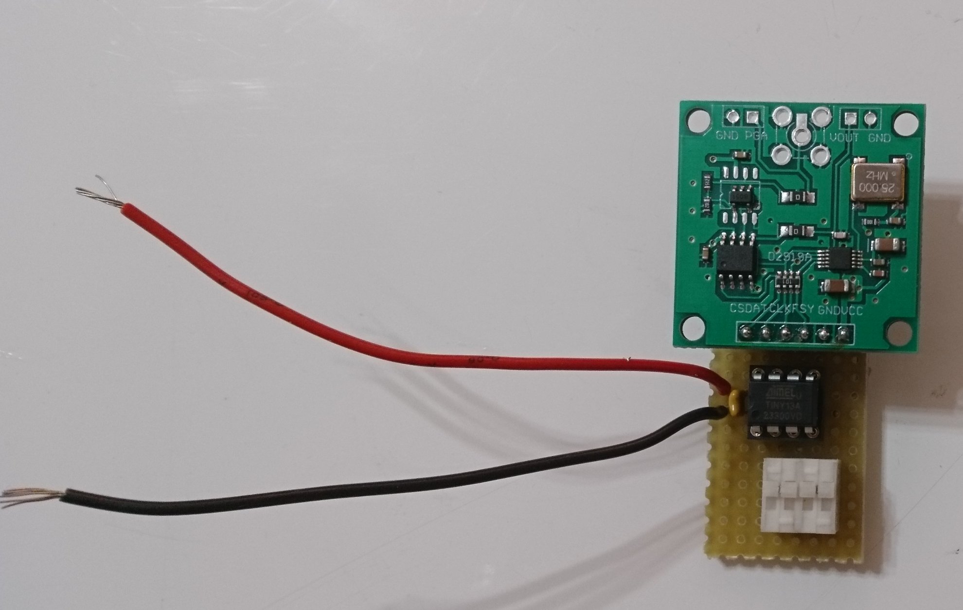
Zwei Leiterplatten mit Kabeln und Bauteilen
GND PGA VOUT GND 25.000 MHZ 029199 CSDA TCK FSY GNDUCC
in „AD9833 Programmieren“ · Mikrocontroller und Digitale Elektronik · · Platinenfotos
-
Bild
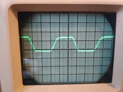
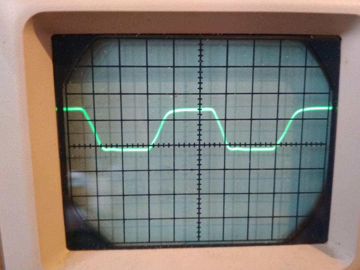
Oszilloskop-Bildschirm mit Rechtecksignal
AD9833__Rechteck.jpg
in „Arduino+AD9833 code für Rechteckfestfrequenz“ · Mikrocontroller und Digitale Elektronik · · Fotos
-
Datei
cfg_ad9833.c
/* * Konfiguration vom AD9833 * */ #include <avr/io.h> #include <avr/sleep.h> // ftw = freq * ACCU_SIZE / F_DDS // = freq * 2^28 / 25e6 Hz // = freq * 10.73741824 // Manuelle Berechnung fuer 5845000 Hz // FTW frequency tuning
in „AD9833 Programmieren“ · Mikrocontroller und Digitale Elektronik ·
-
Datei
Liste.txt
(Stop down) 56x RDW 17-18 5x MC1488 (Quad Eip.232 Driver ) 1X atf-13736 wfk:L78-032A HP ??????? 4x AD7628KR Dual 8-Bit Buffered Multiplying DAC 50x B084D = TL084CN GDR RFT Quad JFET Op Amplifier Audio High Slew Rate HFO 36x gd74ls299 8-BIT SHIFT/STORAGE REGISTER WITH 3-STATE OUTPUTS 25x 907550022 ???
-
Datei
Castillo33.c
0x5515, 0x9551, 0x5916, 0x5689, 0xBD59, 0x5249, 0xD695, 0x5558, 0x0585, 0x96A4, 0x5455, 0x6155, 0x55AD, 0xAD65, 0x68D5, 0x5589, 0xA161, 0x6145, 0x9595, 0x9155, 0xE41E, 0xDF79, 0x30C1, 0x07C7, 0x6D59, 0x5955, 0xF033, 0xD69B, 0x1A3F, 0x011D, 0x1D92, 0x5986, 0x463B, 0x962A, 0x5855, 0x3156, 0x8556, 0x8D58
in „BMP/JPEG/GIF/PNG nach C-Code konvertieren“ · Projekte & Code ·
-
Datei
Castillo33.c
0x5515, 0x9551, 0x5916, 0x5689, 0xBD59, 0x5249, 0xD695, 0x5558, 0x0585, 0x96A4, 0x5455, 0x6155, 0x55AD, 0xAD65, 0x68D5, 0x5589, 0xA161, 0x6145, 0x9595, 0x9155, 0xE41E, 0xDF79, 0x30C1, 0x07C7, 0x6D59, 0x5955, 0xF033, 0xD69B, 0x1A3F, 0x011D, 0x1D92, 0x5986, 0x463B, 0x962A, 0x5855, 0x3156, 0x8556, 0x8D58
in „Bilder umwandeln für C/C++ Code“ · Softwareentwicklung ·
-
Datei
EPROM_0000_7FFF.lst
0ACB 4F LD C,A 1503 0ACC 66 LD H,(HL) 1504 0ACD 6D LD L,L 1505 0ACE 7D LD A,L 1506 0ACF 07 RLCA 1507 0AD0 7F LD A,A 1508 0AD1 6F LD L,A 1509 0AD2 E5 L0426: PUSH HL 1510 0AD3 D5 PUSH DE 1511 0AD4 C5 PUSH BC 1512 0AD5 CD 48 0C L0158: CALL L0156 1513 0AD8 47 LD B,A 1514 0AD9 20 05 JR NZ,L0157 1515 0ADB 32
in „Hilfe bei Z80 Opcodes“ · Mikrocontroller und Digitale Elektronik ·
-
Datei
set-and-map.c
\ _BitInt(0xA9): 0xA9, _BitInt(0xAA): 0xAA, _BitInt(0xAB): 0xAB, _BitInt(0xAC): 0xAC, \ _BitInt(0xAD): 0xAD, _BitInt(0xAE): 0xAE, _BitInt(0xAF): 0xAF, _BitInt(0xB0): 0xB0, \ \ _BitInt(0xB1): 0xB1, _BitInt(0xB2): 0xB2, _BitInt(0xB3): 0xB3, _BitInt(0xB4): 0xB4, \ _BitInt(0xB5): 0xB5, _BitInt(0xB6): 0xB6
in „Diverse fragen zu Hash Maps in C“ · Softwareentwicklung ·
-
Datei
set-and-map.c
\ _BitInt(0xA9): 0xA9, _BitInt(0xAA): 0xAA, _BitInt(0xAB): 0xAB, _BitInt(0xAC): 0xAC, \ _BitInt(0xAD): 0xAD, _BitInt(0xAE): 0xAE, _BitInt(0xAF): 0xAF, _BitInt(0xB0): 0xB0, \ \ _BitInt(0xB1): 0xB1, _BitInt(0xB2): 0xB2, _BitInt(0xB3): 0xB3, _BitInt(0xB4): 0xB4, \ _BitInt(0xB5): 0xB5, _BitInt(0xB6): 0xB6
in „Diverse fragen zu Hash Maps in C“ · Softwareentwicklung ·
-
PDF
JRXEWKbQXBFOb1fH.pdf
sparse all’interno dell’elaboratore. Verificare ciò scuotendo l’elaboratore e prestando attenzione ad eventuali rumori; eventuali parti o pezzetti metallici possono provocare cortocircuiti pericolosi. Antes de encender el sistema despues de sustituir una FRU, compruebe que todos los tornillos, muelles

in „Lenovo T42 Ladeelektronik spielt verrückt“ · Mikrocontroller und Digitale Elektronik ·