-
 Bild
Bild
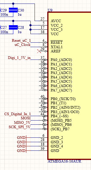
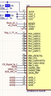
Ausschnitt eines Schaltplans eines ATmega16 Mikrocontrollers
MOSI 2 (MOSI)_PB5 MISO_5V 3 (MISO)_PB6 SCK_SPI_5V 4 (SCK)_PB7 6 GND 28 GND_2 18 GND_3 39 GND_4 GND ATMEGA16-16AUR
in „SPI Kommunikation zwischen AT90CAN und ATmega16 (AVR)“ · Mikrocontroller und Digitale Elektronik · · Schaltpläne
-
 Bild
Bild
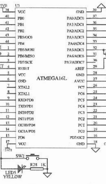
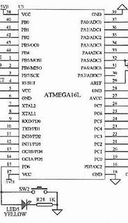
Schaltplan eines ATmega16L Mikrocontrollers
U3 ATMEGA16L VCC PB0 PB1 PB2 PB3/OC0 PB4 PB5/MOSI PB6/MISO PB7/SCK RESET VCC GND XTAL2 XTAL1 RXD/PD0 TXD/PD1 INT0/PD2 INT1/PD3 OC1B/PD4 OC1A/PD5 PD6 VCC 5V PB GND PA0/ADC0 PA1/ADC1 PA2/ADC2 PA3/ADC3 PA4/ADC4
in „Manson HCS-3602 HCS-3600 Reparatur“ · Analoge Elektronik und Schaltungstechnik · · Schaltpläne
-
 Bild
Bild
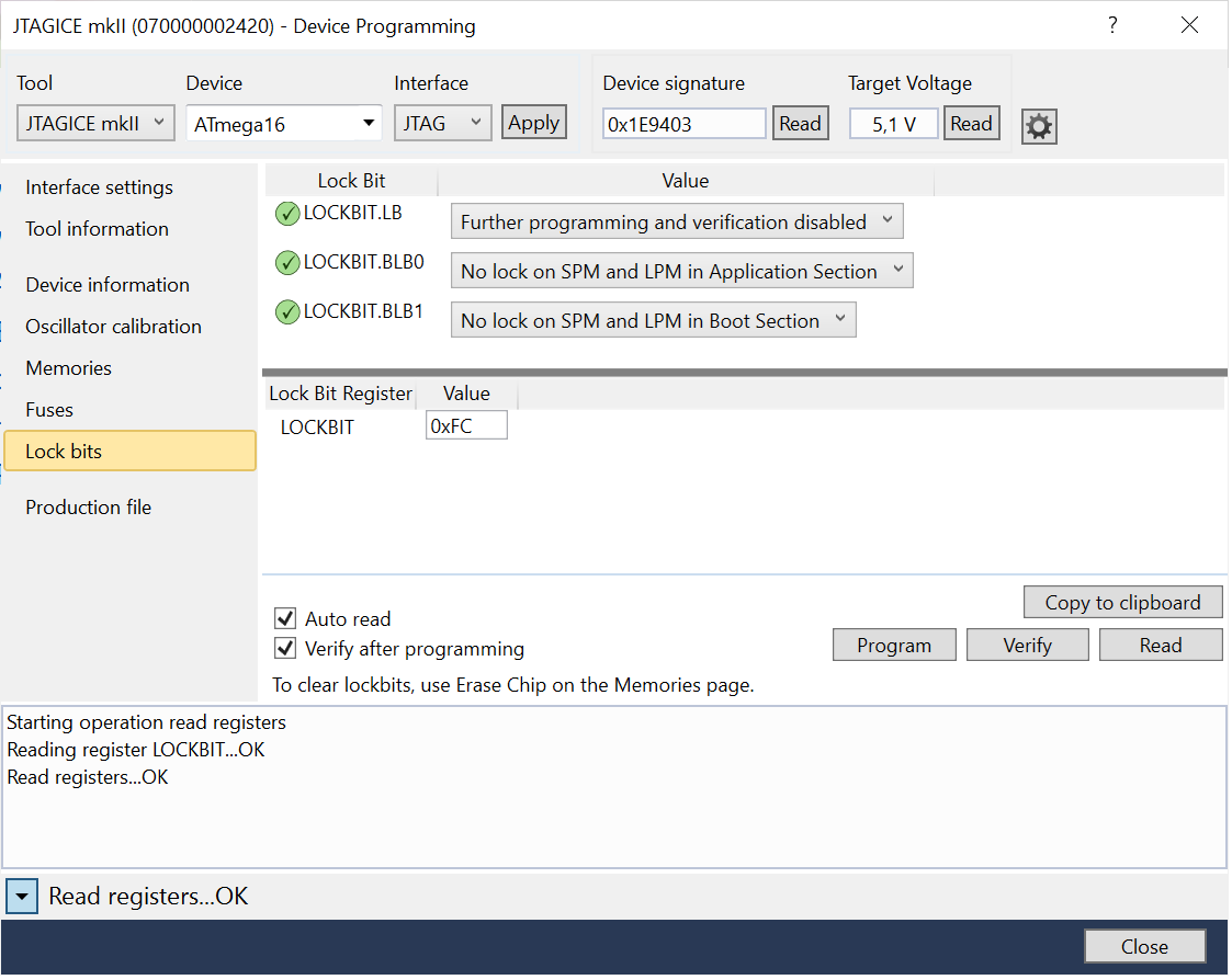
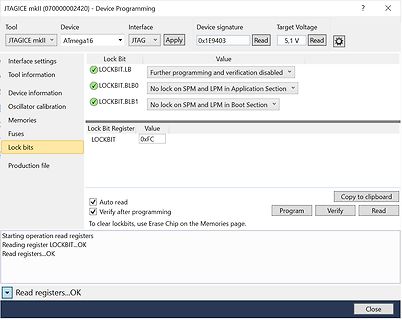
Softwareoberfläche zur Programmierung eines ATmega16 Mikrocontrollers
JTAGICE mkII (07000002420) - Device Programming Tool Device Interface JTAG Apply Device signature 0x1E9403 Target Voltage 5,1 V Read Interface settings LOCKBIT.LB Further programming and verification disabled LOCKBIT.BLB0 No lock on SPM and LPM in Application Section LOCKBIT.BLB1 No lock on SPM and LPM in Boot Section Memories Lock Bit Register Value Fuses LOCKBIT 0xFC Lock bits Production file Auto read Verify after programming Copy to clipboard Program Verify Read To clear lockbits, use Erase Chip on the Memories page. Starting operation read registers Reading register LOCKBIT...OK Read registers
in „mit welchen Lock Bits ist ein ATmega noch lesbar?“ · Mikrocontroller und Digitale Elektronik · · Screenshots
-
 Bild
Bild
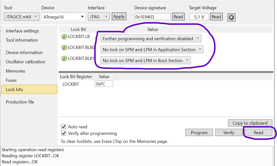
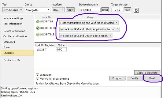
Softwareoberfläche zur Konfiguration der Lockbits eines ATmega16
Tool JTAGICE mkII Device ATmega16 Interface JTAG Apply 0x1E9403 Read Target Voltage 5,1 V Read Lock Bit Value LOCKBIT.LB Further programming and verification disabled LOCKBIT.BLBO No lock on SPM and LPM in Application Section LOCKBIT.BLB1
in „mit welchen Lock Bits ist ein ATmega noch lesbar?“ · Mikrocontroller und Digitale Elektronik · · Screenshots
-
 Bild
Bild
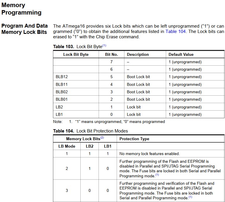
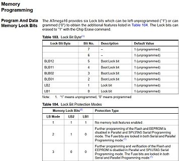
Datenblatt Ausschnitt ATmega16 Lock Bits
Memory Programming Program And Data Memory Lock Bits The ATmega16 provides six Lock bits... Table 103. Lock Bit Byte Lock Bit Byte | Bit No. | Description | Default Value BLB12 | 5 | Boot Lock bit | 1 (unprogrammed) BLB11 | 4 | Boot Lock bit | 1 (unprogrammed)
in „mit welchen Lock Bits ist ein ATmega noch lesbar?“ · Mikrocontroller und Digitale Elektronik · · Screenshots
-
 Bild
Bild
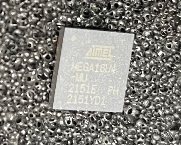
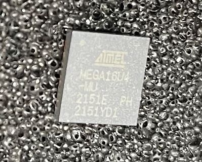
Atmel ATmega16U4 Mikrocontroller
ATMEL ATmega16U4 2151E PH 2151YDI
in „[V] 3 Stück ATMEGA16U4-MU - QFN-44“ · Markt · · Fotos
-
 Bild
Bild
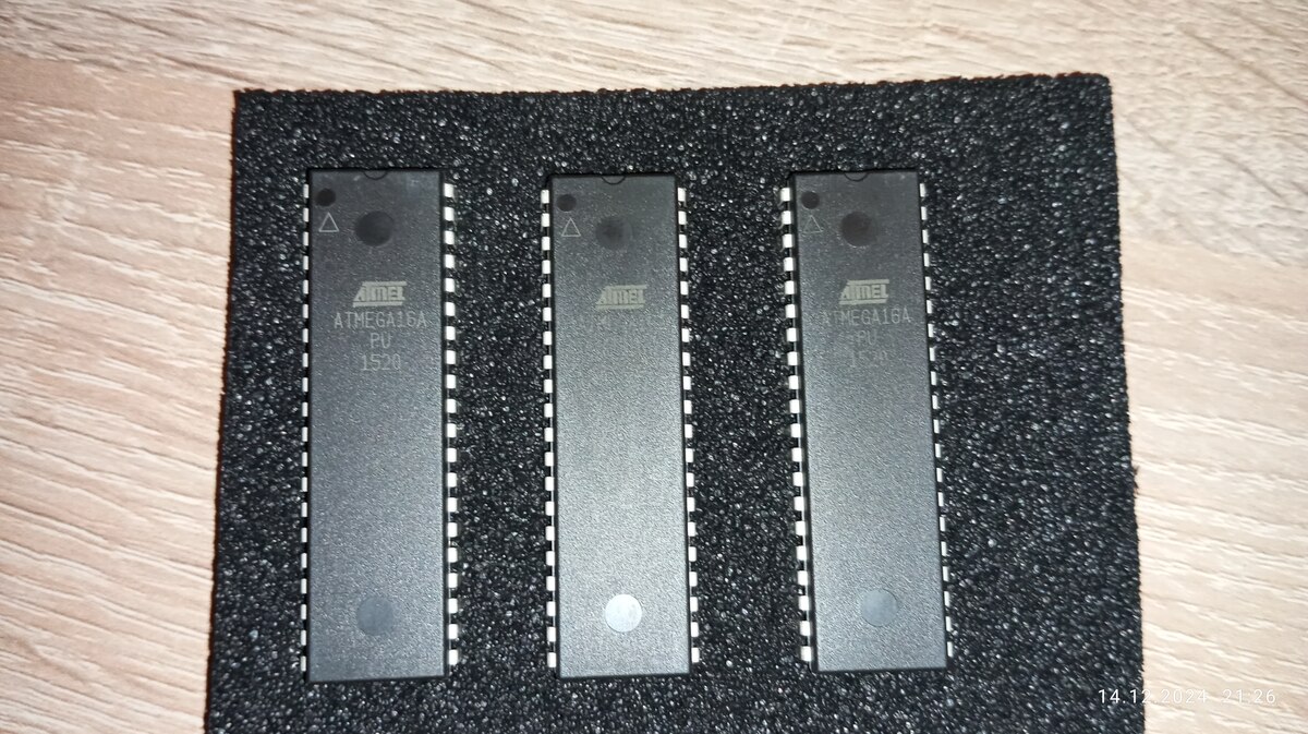
Drei ATmega16A Mikrocontroller auf Schaumstoff
ATMEL ATMEGA16A PU 1520
in „[V] Diverse IC, Controller, Relais, LCD 16x2“ · Markt · · Fotos

-
 Bild
Bild
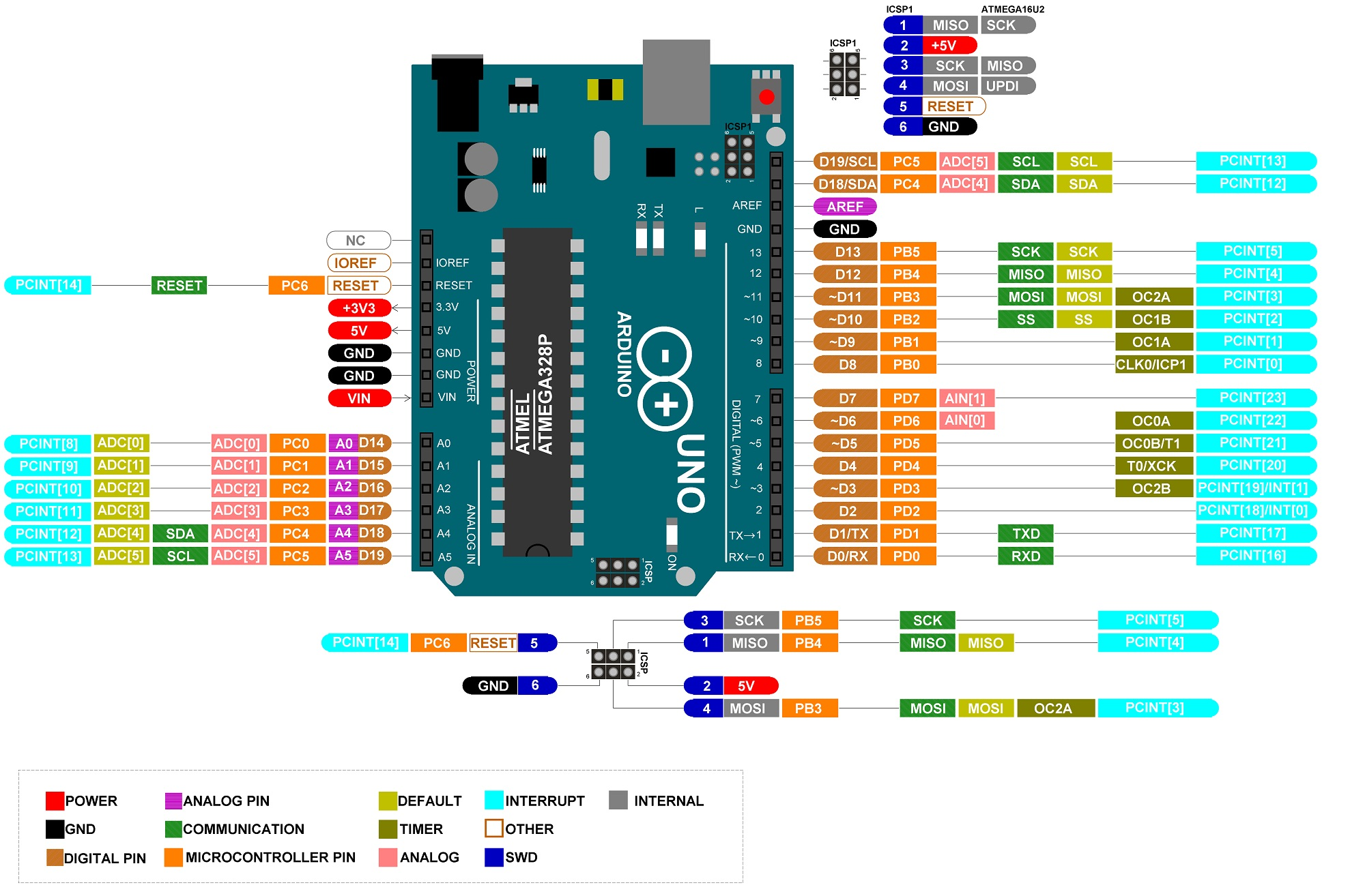
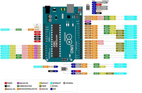
Pinbelegung eines Arduino Uno und ATmega16U2
ICSP1 ATmega16U2 1 MISC 2 +5V 3 SCK MOSI 4 RESET UPDI 5 GND 6 GND NC IOREF RESET PC6 +3V3 VIN GND GND 5V GND 3.3V RESET IOREF NC RESET PC6 +5V SDA SCL ADC[5] ADC[4] SDA SCL PCINT[13] PCINT[14] D19 A0 D14 A1 D15
in „LCD-Display mit Arduino will nicht“ · Mikrocontroller und Digitale Elektronik · · Diagramme
-
 Bild
Bild
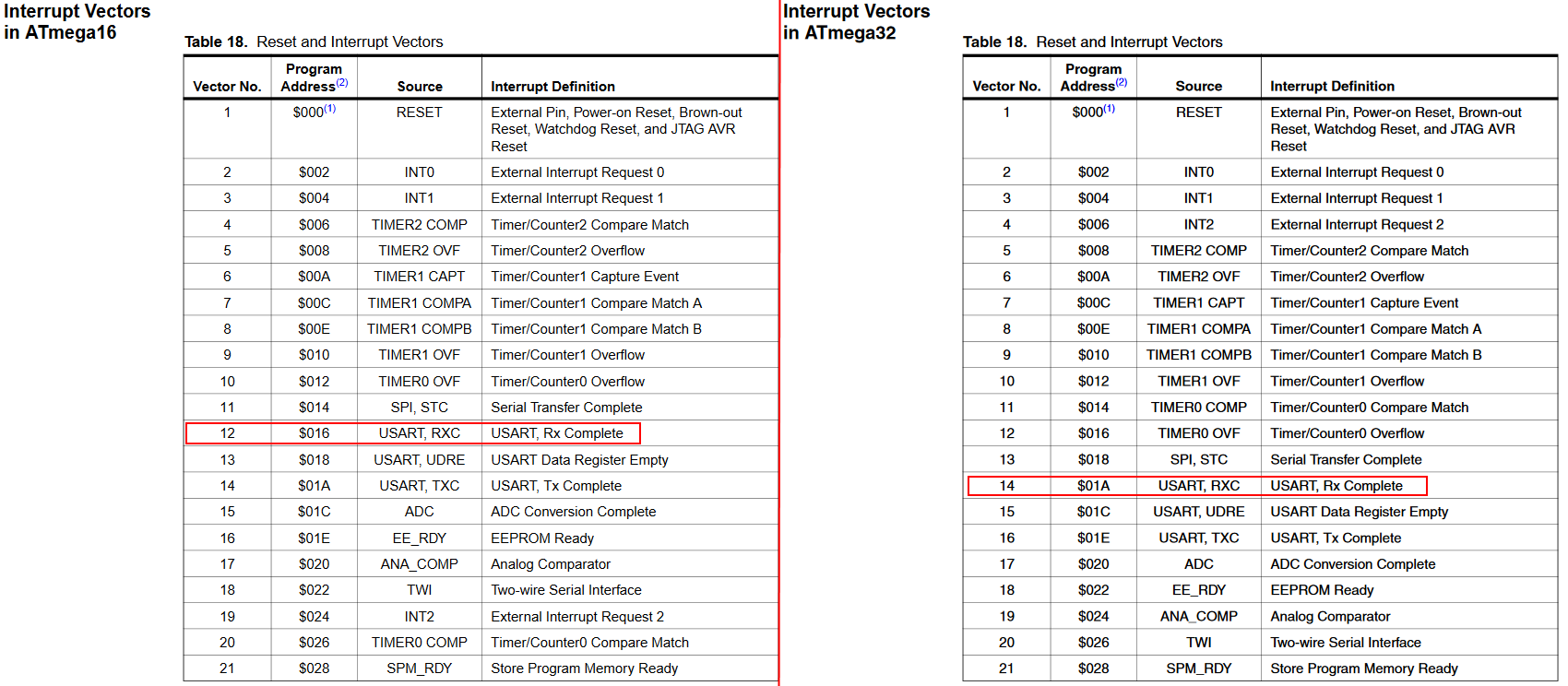
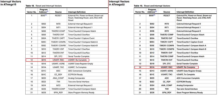
Tabelle der Interrupt-Vektoren für ATmega16 und ATmega32
Interrupt Vectors in ATmega16 Table 18. Reset and Interrupt Vectors Vector No. | Address | Source | Interrupt Definition 1 | $000 | RESET | External Pin, Power-on Reset, Brown-out Reset, Watchdog Reset, and JTAG AVR Reset 2 |
in „Hex File von Atmega16 in Atmega32 verwandeln“ · Mikrocontroller und Digitale Elektronik · · Screenshots
-
 Bild
Bild
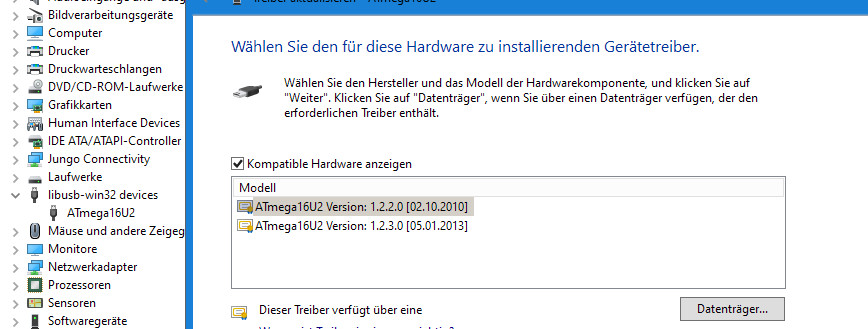
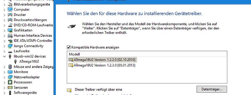
Windows Treiberinstallations-Dialog für Atmega16U2
Datenträger verfügen, der den erforderlichen Treiber enthält. Kompatible Hardware anzeigen Modell ATmega16U2 Version: 1.2.2.0 [02.10.2010] ATmega16U2 Version: 1.2.3.0 [05.01.2013] Dieser Treiber verfügt über eine Datenträger...
in „Atmega32U4 per Flip flashen und als COM-Port in Terminalprogramm ansprechbar“ · Mikrocontroller und Digitale Elektronik · · Screenshots
-
Datei
ATMega16.txt
.include "m16def.inc" .equ CLOCK = 6000000 ;Taktfrequenz für Quarz .equ BAUD = 9600 ;Baudrate von RS232 .equ UBRRVAL = CLOCK/(BAUD*16)-1 ;Ausrechnen der Baudrate .def Temp = r16 ;Temporäres Register .def Tmp = r17 ;Temporäres Register ;$000 RESET External Pin, Power-on Reset, Brown-out ;$002 INT0 External Interrupt Request 0 ;$004 INT1 External Interrupt Request 1 ;$006 TIMER2 COMP Timer/Counter2 Compare Match ;$008 TIMER2 OVF Timer/Counter2 Overflow ;$00A TIMER1 CAPT Timer/Counter1 Capture Event ;$00C TIMER1 COMPA Timer/Counter1 Compare Match A ;$00E TIMER1 COMPB Timer/Counter1 Compare Match B ;$010
in „Warum zählt mein AD-Wandler nicht richtig?“ · Mikrocontroller und Digitale Elektronik ·
-
PDF
ATMega16.pdf
Programmable I/O Lines – 40-pin PDIP, 44-lead TQFP, and 44-pad MLF Operating Voltages – 2.7 - 5.5V for ATmega16L – 4.5 - 5.5V for ATmega16 Speed Grades – 0 - 8 MHz for ATmega16L – 0 - 16 MHz for ATmega16 Rev. 2466E–AVR–10/02 1 Pin Configurations Figure 1. Pinouts ATmega16 PDIP (XCK/T0) PB0 PA0 (ADC0) (T1)
in „DCF auf INT0“ · Mikrocontroller und Digitale Elektronik ·
-
Datei
Atmega16_vs_Atmega644.cpp
<avr/io.h> #include <avr/interrupt.h> void ioinitB(void) { #if defined (__AVR_ATmega16__) /**PIN 1..8*/ //PB0 (XCK/T0) //PB1 (T1) //PB2 (INT2/AIN0) //PB3 (OC0/AIN1) //PB4 (_SS) //PB5 (MOSI) //PB6 (MISO) //PB7 (SCK) #endif #if defined (__AVR_ATmega644__) /**PIN 1..8*/ //PB0 (XCK/T0)
in „Umstieg Atmega16 auf Atmega644“ · Mikrocontroller und Digitale Elektronik ·
-
 Bild
Bild
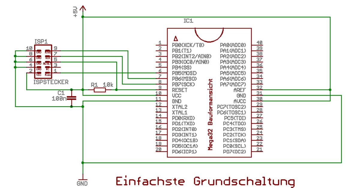
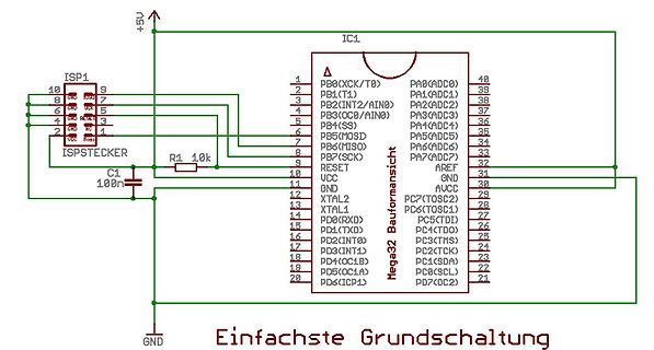
Schaltplan eines ATmega32 Mikrocontrollers
ISP1, 10, 9, 8, 7, 6, 5, 4, 3, 2, 1, VCC, MOSI, MISO, GND, RESET, R1 10k, C1 100n, IC1, Mega32 Bauformansicht, +5V, PB0(XCK/T0), PB1(T1), PB2(INT2/AIN0), PB3(OC0B/AIN0), PB4(SS), PB5(MOSI), PB6(MISO), PB7(SCK), RESET, VCC, GND, XTAL2, XTAL1, PD0(RXD), PD1(TXD), PD2(INT0), PD3(INT1), PD4(OC1A), PD5(OC1B), PD6(ICP1), PA0(ADC0), PA1(ADC1), PA2(ADC2), PA3(ADC3), PA4(ADC4), PA5(ADC5), PA6(ADC6), PA7(ADC7), AREF, GND, AVCC, TOSC2, TOSC1, TDI, TDO, TMS, TCK, SDA, SCL, DC2, GND, Einfachste Grundschaltung
in „Ermittlung maximal Spanung mit atmega“ · Mikrocontroller und Digitale Elektronik · · Schaltpläne
-
Datei
ATMega16b.txt
.include "m16def.inc" .equ CLOCK = 6000000 ;Taktfrequenz für Quarz .equ BAUD = 9600 ;Baudrate von RS232 .equ UBRRVAL = CLOCK/(BAUD*16)-1 ;Ausrechnen der Baudrate .def Temp = r16 ;Temporäres Register .def Tmp = r17 ;Temporäres Register ;$000 RESET External Pin, Power-on Reset, Brown-out ;$002 INT0 External Interrupt Request 0 ;$004 INT1 External Interrupt Request 1 ;$006 TIMER2 COMP Timer/Counter2 Compare Match ;$008 TIMER2 OVF Timer/Counter2 Overflow ;$00A TIMER1 CAPT Timer/Counter1 Capture Event ;$00C TIMER1 COMPA Timer/Counter1 Compare Match A ;$00E TIMER1 COMPB Timer/Counter1 Compare Match B ;$010
in „Warum zählt mein AD-Wandler nicht richtig?“ · Mikrocontroller und Digitale Elektronik ·
-
Datei
Atmega16_1.c
#include <avr/io.h> //Bibliotheken(Headerfiles einbinden) #include <avr/interrupt.h> #include <stdint.h> #define F_CPU 16000000UL #define BAUD 9600UL #define UBRR_WERT ((F_CPU/(16UL*BAUD))-1) //16MHz/((16UL*9600UL)-1)= 104,16 //Variablendeklaration char Aktor_1bis8; char Sensor_1bis8; char Sensor_9bis12; int main (void) { //DDRA = 0xFF; //Datenrichtungsregister A als Ausgänge geschaltet Aktoren DDRC = 0x00; //Datenrichtungsregister C als Eingänge geschaltet Sensoren //DDRB = 0x00; //DDR B Port 0 bis 3 als Eingänge PORTC = 0xFF; //interne Pull-Ups an allen Port-Pins aktivieren //PORTB = 0xf; //interne
in „bidirektionale Datenübertragung zwischen 2 Atmega 8“ · Mikrocontroller und Digitale Elektronik ·
-
Datei
Atmega16_2.c
#include <avr/io.h> //Bibliotheken(Headerfiles einbinden) #include <avr/interrupt.h> #include <stdint.h> #define F_CPU 16000000UL #define BAUD 9600UL #define UBRR_WERT ((F_CPU/(16UL*BAUD))-1) //16MHz/((16UL*9600UL)-1)= 104,16 //Variablendeklaration //uint8_t Sensor_1bis6; char SPS_in1bis8; char SPS_in9bis12; char SPS_out1bis8; int main (void) { DDRA = 0xFF; //Datenrichtungsregister A alles Ausgänge //DDRB = 0xf; //DDRD 0 bis 3 Ausgänge //DDRC = 0x00; //DDRC Eingänge //PORTC = 0xFF; //interne Pull-Ups an allen Port-Pins aktivieren init_uart(UBRR_WERT); //Aufruf von uartinitialisierung übergabe von UBRR_Wert
in „bidirektionale Datenübertragung zwischen 2 Atmega 8“ · Mikrocontroller und Digitale Elektronik ·
-
Datei
Atmega16_1.c
#include <avr/io.h> //Bibliotheken(Headerfiles einbinden) #include <avr/interrupt.h> #include <stdint.h> #define F_CPU 16000000UL #define BAUD 9600UL #define UBRR_WERT ((F_CPU/(16UL*BAUD))-1) //16MHz/((16UL*9600UL)-1)= 104,16 //Variablendeklaration char Aktor_1bis8; char Sensor_1bis8; char Sensor_9bis12; int main (void) { DDRA = 0xFF; //Datenrichtungsregister A als Ausgänge geschaltet Aktoren DDRC = 0x00; //Datenrichtungsregister C als Eingänge geschaltet Sensoren PORTC = 0xFF; //interne Pull-Ups an allen Port-Pins aktivieren init_uart(UBRR_WERT); //Aufruf von uartinitialisierung übergabe von UBRR_Wert
in „bidirektionale Datenübertragung zwischen 2 Atmega 8“ · Mikrocontroller und Digitale Elektronik ·
-
Datei
Atmega16_2.c
#include <avr/io.h> //Bibliotheken(Headerfiles einbinden) #include <avr/interrupt.h> #include <stdint.h> #define F_CPU 16000000UL #define BAUD 9600UL #define UBRR_WERT ((F_CPU/(16UL*BAUD))-1) //16MHz/((16UL*9600UL)-1)= 104,16 //Variablendeklaration //uint8_t Sensor_1bis6; char SPS_in1bis8; char SPS_in9bis12; char SPS_out1bis8; int main (void) { DDRA = 0xFF; //Datenrichtungsregister A alles Ausgänge DDRC = 0x00; //DDRC Eingänge PORTC = 0xFF; //interne Pull-Ups an allen Port-Pins aktivieren init_uart(UBRR_WERT); //Aufruf von uartinitialisierung übergabe von UBRR_Wert init_timer(); //Aufruf von timerinitialisierung
in „bidirektionale Datenübertragung zwischen 2 Atmega 8“ · Mikrocontroller und Digitale Elektronik ·
-
Datei
Atmega16_1.c
#include <avr/io.h> //Bibliotheken(Headerfiles einbinden) #include <avr/interrupt.h> #include <stdint.h> #define F_CPU 16000000UL #define BAUD 9600UL #define UBRR_WERT ((F_CPU/(16UL*BAUD))-1) //16MHz/((16UL*9600UL)-1)= 104,16 //Variablendeklaration uint8_t Sensor_1bis6; uint8_t Sensor_7bis12; int main (void) { DDRA = 0xFF; //Datenrichtungsregister A als Ausgänge geschaltet Aktoren DDRB = 0x00; PORTB = 0x3F; DDRC = 0x00; //Datenrichtungsregister C als Eingänge geschaltet Sensoren PORTC = 0x3F; //interne Pull-Ups an allen Port-Pins aktivieren init_uart(UBRR_WERT); //Aufruf von uartinitialisierung
in „bidirektionale Datenübertragung zwischen 2 Atmega 8“ · Mikrocontroller und Digitale Elektronik ·
-
Datei
Atmega16_2.c
#include <avr/io.h> //Bibliotheken(Headerfiles einbinden) #include <avr/interrupt.h> #include <stdint.h> #define F_CPU 16000000UL #define BAUD 9600UL #define UBRR_WERT ((F_CPU/(16UL*BAUD))-1) //16MHz/((16UL*9600UL)-1)= 104,16 //Variablendeklaration uint8_t rx_data; uint8_t SPS_in1bis6; uint8_t SPS_in7bis12; uint8_t SPS_out1bis8; int main (void) { DDRA = 0x3F; //Datenrichtungsregister A alles Ausgänge DDRB = 0x3F; //niedrigsten 4 Bit als Ausgang DDRC = 0x00; //DDRC Eingänge PORTC = 0xFF; //interne Pull-Ups an allen Port-Pins aktivieren init_uart(UBRR_WERT); //Aufruf von uartinitialisierung übergabe von
in „bidirektionale Datenübertragung zwischen 2 Atmega 8“ · Mikrocontroller und Digitale Elektronik ·
-
Datei
Atmega16_1.c
#include <avr/io.h> //Bibliotheken(Headerfiles einbinden) #include <avr/interrupt.h> #include <stdint.h> #define F_CPU 4000000UL #define BAUD 9600UL #define UBRR_WERT ((F_CPU/(16UL*BAUD))-1) //16MHz/((16UL*9600UL)-1)= 104,16 //Variablendeklaration uint8_t Sensor_1bis6; uint8_t Sensor_7bis12; uint8_t negiert_Sensor_1bis6; uint8_t negiert_Sensor_7bis12; int main (void) { DDRA = 0xFF; //Datenrichtungsregister A als Ausgänge geschaltet Aktoren DDRB = 0x00; PORTB = 0x3F; DDRC = 0x00; //Datenrichtungsregister C als Eingänge geschaltet Sensoren PORTC = 0x3F; //interne Pull-Ups an allen Port-Pins aktivieren
in „bidirektionale Datenübertragung zwischen 2 Atmega 8“ · Mikrocontroller und Digitale Elektronik ·
-
Datei
Atmega16_2.c
#include <avr/io.h> //Bibliotheken(Headerfiles einbinden) #include <avr/interrupt.h> #include <stdint.h> #define F_CPU 4000000UL #define BAUD 9600UL #define UBRR_WERT ((F_CPU/(16UL*BAUD))-1) //16MHz/((16UL*9600UL)-1)= 104,16 //Variablendeklaration uint8_t rx_data; uint8_t SPS_in1bis6; uint8_t negiert1bis6; uint8_t SPS_in7bis12; uint8_t negiert7bis12; uint8_t SPS_out1bis8; uint8_t code; int main (void) { DDRA = 0x3F; //Datenrichtungsregister A alles Ausgänge DDRB = 0x3F; //niedrigsten 4 Bit als Ausgang DDRC = 0x00; //DDRC Eingänge PORTC = 0xFF; //interne Pull-Ups an allen Port-Pins aktivieren init_uart
in „bidirektionale Datenübertragung zwischen 2 Atmega 8“ · Mikrocontroller und Digitale Elektronik ·
-
Datei
atmega16_2.c
#include <avr/io.h> //Bibliotheken(Headerfiles einbinden) #include <avr/interrupt.h> #define F_CPU 4000000UL #define BAUD 9600UL #define UBRR_WERT ((F_CPU/(16UL*BAUD))-1) //16MHz/((16UL*9600UL)-1)= 104,16 //Variablendeklaration uint8_t rx_data; uint8_t SPS_in1bis6; uint8_t negiert1bis6; uint8_t SPS_in7bis12; uint8_t negiert7bis12; uint8_t SPS_out1bis8; uint8_t code; void init_timer(void) { //Initialisierung des Timers: TCCR0 |= (0<<CS00)|(0<<CS01)|(1<<CS02); //Quarztakt wird durch 256 geteilt 4MHz/1024=15625Hz TCNT0 = 100; // Vorladen 15625Hz/101,16Hz(9,984ms)=156 256-156=100 TIMSK |= (1<<TOIE0); // Interrupts
in „bidirektionale Datenübertragung zwischen 2 Atmega 8“ · Mikrocontroller und Digitale Elektronik ·
-
Datei
Atmega16_1.c
#include <avr/io.h> //Bibliotheken(Headerfiles einbinden) #include <avr/interrupt.h> #include <stdint.h> #define F_CPU 4000000UL #define BAUD 9600UL #define UBRR_WERT ((F_CPU/(16UL*BAUD))-1) //16MHz/((16UL*9600UL)-1)= 104,16 //Variablendeklaration uint8_t Sensor_1bis6; uint8_t Sensor_7bis12; uint8_t negiert_Sensor_1bis6; uint8_t negiert_Sensor_7bis12; void init_timer(void) { //Initialisierung des Timers: TCCR0 |= (0<<CS00)|(0<<CS01)|(1<<CS02); //Quarztakt wird durch 1024 geteilt 4MHz/1024=15625Hz TCNT0 = 100; // Vorladen 15625Hz/101,16Hz(9,984ms)=156 256-156=100 TIMSK |= (1<<TOIE0); // Interrupts
in „bidirektionale Datenübertragung zwischen 2 Atmega 8“ · Mikrocontroller und Digitale Elektronik ·
-
Datei
Atmega16_1.c
#include <avr/io.h> //Bibliotheken(Headerfiles einbinden) #include <avr/interrupt.h> #include <stdint.h> #define F_CPU 4000000UL #define BAUD 19200UL #define UBRR_WERT ((F_CPU/(16UL*BAUD))-1) //16MHz/((16UL*9600UL)-1)= 104,16 //Variablendeklaration uint8_t Sensor_1bis6; uint8_t Sensor_7bis12; uint8_t negiert_Sensor_1bis6; uint8_t negiert_Sensor_7bis12; uint8_t rx_data; uint8_t code; uint8_t Aktor_1bis4; uint8_t Aktor_1bis4_negiert; uint8_t Aktor_5bis8; uint8_t Aktor_5bis8_negiert; uint8_t Aktor_1bis8; uint8_t Aktor_1bis8_negiert; void init_timer(void) { //Initialisierung des Timers: TCCR0 |= (
in „bidirektionale Datenübertragung zwischen 2 Atmega 8“ · Mikrocontroller und Digitale Elektronik ·
-
Datei
Atmega16_2.c
#include <avr/io.h> //Bibliotheken(Headerfiles einbinden) #include <avr/interrupt.h> #include <stdint.h> #define F_CPU 4000000UL #define BAUD 19200UL #define UBRR_WERT ((F_CPU/(16UL*BAUD))-1) //16MHz/((16UL*9600UL)-1)= 104,16 //Variablendeklaration //tx uint8_t tx_data; uint8_t send1; uint8_t send2; uint8_t send1_negiert; uint8_t send2_negiert; //rx uint8_t rx_data; uint8_t SPS_in1bis6; uint8_t negiert1bis6; uint8_t SPS_in7bis12; uint8_t negiert7bis12; uint8_t SPS_out1bis8; uint8_t code; void init_timer(void) { //Initialisierung des Timers: TCCR0 |= (0<<CS00)|(0<<CS01)|(1<<CS02); //Quarztakt wird
in „bidirektionale Datenübertragung zwischen 2 Atmega 8“ · Mikrocontroller und Digitale Elektronik ·
-
Datei
Atmega16_1.c
#include <avr/io.h> //Bibliotheken(Headerfiles einbinden) #include <avr/interrupt.h> #include <stdint.h> //#include "lcd_routines.h" //#include <stdlib.h> #define F_CPU 4000000UL #define BAUD 19200UL #define UBRR0_WERT ((F_CPU/(16UL*BAUD))-1) //16MHz/((16UL*9600UL)-1)= 104,16 //Variablendeklaration uint8_t Sensor_1bis6; uint8_t Sensor_7bis12; uint8_t negiert_Sensor_1bis6; uint8_t negiert_Sensor_7bis12; int16_t Fehler = 0; void init_timer(void) { //Initialisierung des Timers: TCCR0A |= (0<<CS00)|(0<<CS01)|(1<<CS02); //Quarztakt wird durch 256 geteilt 4MHz/1024=15625Hz TCNT0 = 178; // Vorladen 15625Hz
in „bidirektionale Datenübertragung zwischen 2 Atmega 8“ · Mikrocontroller und Digitale Elektronik ·
-
Datei
Atmega16_LCD.asm
;;;;;;;;;;;;;;;;;;;;;;;;;;;;;;;;;;;;;;;;;;;;;;;;; ;; LCD-Routinen ;; ;; ============ ;; ;; (c)andreas-s@web.de ;; ;; ;; ;; 4bit-Interface ;; ;; DB4-DB7: PA0-PA3 ;; ;; RS: PA4 ;; ;; E: PA5 ;; ;;;;;;;;;;;;;;;;;;;;;;;;;;;;;;;;;;;;;;;;;;;;;;;;; .equ LCD_PORT = PORTA .equ LCD_DDR = DDRA .equ PIN_RS = 4 .equ PIN_E = 5 .ifndef XTAL .equ XTAL = 8000000 .endif ;sendet ein Datenbyte an das LCD lcd_data: push temp2 push temp3 mov temp2, temp1 ; "Sicherungskopie" für ; die Übertragung des 2.Nibbles swap temp1 ; Vertauschen andi temp1, 0b00001111 ; oberes Nibble auf Null setzen sbr temp1, 1<<PIN_RS ; entspricht
in „LCD nur 8 von 16 zeichen lassen sich beschreiben“ · Mikrocontroller und Digitale Elektronik ·
-
Datei
DMX_ATmega16.txt
//HEADERFILES #include <avr/io.h> #include <util/delay.h> #include <avr/interrupt.h> #include <avr/stdint.h> #include <math.h> #include <avr/sleep.h> //DEFINES #define F_CPU 8000000 //Taktfrequenz 8MHz #define dmx_size 1 //Anzahl benötigter Kanäle ==> ANPASSEN #define BAUD 250000L //Baudrate von DMX512 = 250kBaud #define UBRR_VAL ((F_CPU+BAUD*8)/(BAUD*16)-1) #define BAUD_REAL (F_CPU/(16*(UBRR_VAL+1))) #define BAUD_ERROR ((BAUD_REAL*1000)/BAUD-1000) #if ((BAUD_ERROR>10) || (BAUD_ERROR<-10)) #error Systematischer Fehler der Baudrate grösser 1% und damit zu hoch! #endif //GLOBALE VARIABLEN uint8_t dmx_array
in „DMX Empfang mit Atmega16 funktioniert leider nicht“ · Mikrocontroller und Digitale Elektronik ·
-
Datei
DMX_ATmega16.c
//HEADERFILES #include <avr/io.h> #include <util/delay.h> #include <avr/interrupt.h> #include <avr/stdint.h> #include <math.h> #include <avr/sleep.h> //DEFINES #define F_CPU 8000000 //Taktfrequenz 8MHz #define dmx_size 1 //Anzahl benötigter Kanäle ==> ANPASSEN #define BAUD 250000L //Baudrate von DMX512 = 250kBaud #define UBRR_VAL ((F_CPU+BAUD*8)/(BAUD*16)-1) #define BAUD_REAL (F_CPU/(16*(UBRR_VAL+1))) #define BAUD_ERROR ((BAUD_REAL*1000)/BAUD-1000) #if ((BAUD_ERROR>10) || (BAUD_ERROR<-10)) #error Systematischer Fehler der Baudrate grösser 1% und damit zu hoch! #endif //GLOBALE VARIABLEN uint8_t dmx_array
in „DMX Empfang mit Atmega16 funktioniert leider nicht“ · Mikrocontroller und Digitale Elektronik ·
-
Datei
ADC_ATmega16.asm
.include "m16def.inc" .def temp = R16 ldi temp, 0xFF ;PORT B auf Ausgang out DDRB, temp ldi temp, 0x00 ;Port A auf Eingang out DDRA, temp ldi temp, 0xFF ;LEDS ausschalten Port B out PORTB, temp cbi ADMUX, REFS1 ; AREF as Voltage Reference cbi ADMUX, REFS0 cbi ADMUX, MUX4 ; Single Ended Input ADC0 cbi ADMUX, MUX3 cbi ADMUX, MUX2 cbi ADMUX, MUX1 cbi ADMUX, MUX0 sbi ADCSRA, ADEN ; ADC enable sbi ADCSRA, 2 ; Abtast Frequenz Teiler 20 cbi ADCSRA, 1 sbi ADCSRA, 0 sbi ADCSRA, ADFR ; Free Run messen: sbi ADCSRA, ADSC ; Start Conversion ready: sbic ADCSRA, ADSC rjmp ready ldi temp, ADCL out PORTB, temp
in „Wiederstandsmessung mit ATmega16“ · Mikrocontroller und Digitale Elektronik ·
-
Datei
ADC_ATmega16.asm
; PORTA.0 IN Volume Poti Wert ; PORTA.1 OUT Volume Motor Treiber up ; PORTA.2 OUT Volume Motor Treiber down ; PORTB OUT Leds .include "m16def.inc" .def temp = R16 .def temp2 = R17 ldi temp, 0xFF ;PORT B auf Ausgang out DDRB, temp ldi temp, 0b11111110 ;Port A Pin 0 auf Eingang, 1-7 Ausgang out DDRA, temp ldi temp, 0xFF ;LEDS ausschalten Port B out PORTB, temp cbi ADMUX, REFS1 ; AREF as Voltage Reference cbi ADMUX, REFS0 cbi ADMUX, MUX4 ; Single Ended Input ADC0 cbi ADMUX, MUX3 cbi ADMUX, MUX2 cbi ADMUX, MUX1 cbi ADMUX, MUX0 sbi ADCSRA, ADEN ; ADC enable sbi ADCSRA, 2 ; Abtast Frequenz Teiler 20
in „Wiederstandsmessung mit ATmega16“ · Mikrocontroller und Digitale Elektronik ·
-
Datei
Atmega_16_test.c
#include <avr/io.h> #include <avr/interrupt.h> #define F_CPU 2000000 #include <util/delay.h> #include <inttypes.h> #include <stdint.h> // Anchlussbelegung: #define KTEMP_DDR DDRD //Temperatur Input vom Kältebad #define WTEMP_DDR DDRC //Temperatur Input vom Wärmebad #define PTEMP_DDR DDRA //Temperatur Input von Probe #define MOTOR_DDR DDRB //Datenrichtung zum Motor-Steuer-Atmega festlegen #define MOTOR_OUT PORTB //Ausgänge zum Motor-Steuer-Atmega #define MOTOR_IN PINB //cw = clockwise = im Uhrzeigersinn; ccw = counter clockwise = entgegen dem Uhrzeigersinn #define CW PB0 //Motor cw Richtung Kältebad
in „Anfängerfrage zu switch case“ · Mikrocontroller und Digitale Elektronik ·
-
Datei
Atmega_16_test.c
#include <avr/io.h> #include <avr/interrupt.h> #define F_CPU 2000000 #include <util/delay.h> #include <inttypes.h> #include <stdint.h> // Anchlussbelegung: #define KTEMP_DDR DDRD //Temperatur Input vom Kältebad #define WTEMP_DDR DDRC //Temperatur Input vom Wärmebad #define PTEMP_DDR DDRA //Temperatur Input von Probe #define MOTOR_DDR DDRB //Datenrichtung zum Motor-Steuer-Atmega festlegen #define MOTOR_OUT PORTB //Ausgänge zum Motor-Steuer-Atmega #define MOTOR_IN PINB //cw = clockwise = im Uhrzeigersinn; ccw = counter clockwise = entgegen dem Uhrzeigersinn #define CW PB0 //Motor cw Richtung Kältebad
in „Anfängerfrage zu switch case“ · Mikrocontroller und Digitale Elektronik ·
-
Datei
Atmega16A.c
#include <avr/io.h> #include <avr/interrupt.h> #include <avr/wdt.h> #define DDR_SPI DDRB #define DD_MISO (1<<6) #define DD_MOSI (1<<5) #define DD_SS (1<<4) #define DD_SCK (1<<7) void init_spi_slave(){ DDR_SPI|= DD_MISO; // output DDR_SPI&=~(DD_MOSI | DD_SCK | DD_SS); // inputs, PB4 = SS SPCR = (0<<MSTR)| // not Master -> so it is 0 (1<<SPIE)| // enable SPI interrupt (1<<SPE )| // enable SPI (1<<SPR1)|(1<<SPR0)| // SCK = f_osc / 128 ... no effect on slave (0<<DORD)| // 0 = MSB first (default) (1<<CPOL)| (1<<CPHA); /* INT2 will be connected in parallel to SS-Pin, to get an Interrupt on rising edges
in „(AVR) SPI_Master mit (AVR) API_Slave wie geht's richtig?“ · Mikrocontroller und Digitale Elektronik ·
-
Datei
ATMega16_UartEmpfangen.txt
.include "m16def.inc" .equ CLOCK = 6000000 ;Taktfrequenz für Quarz .equ BAUD = 9600 ;Baudrate von RS232 .equ UBRRVAL = CLOCK/(BAUD*16)-1 ;Ausrechnen der Baudrate .def Temp = r16 ;Temporäres Register .def Send = r17 jmp Reset ;Reset Handler reti ;IRQ0 Handler reti ;IRQ1 Handler reti ;Timer2 Compare Handler reti ;Timer2 Overflow Handler reti ;Timer1 Capture Handler reti ;Timer1 CompareA Handler reti ;Timer1 CompareB Handler reti ;Timer1 Overflow Handler reti ;Timer0 Overflow Handler reti ;SPI Transfer Complete Handler jmp int_rxc ;USART RX Complete Handler reti ;UDR Empty Handler reti ;USART TX Complete
in „Kann über Uart nichts empfangen“ · Mikrocontroller und Digitale Elektronik ·
-
Datei
seriell_atmega16_2.asm
;***************************************************************************** ; ;Seriell-Uebertragung .include "m16def.inc" ;***************************************************************************** ;Baudrate berechnen: ;Die Baudrate berechnet sich nach der Formel: ;Baudrate = Quarzfrequenz / 16*(UBRR-1) ;***************************************************************************** .equ fck = 10000000 ;Quarzfrequenz in Hz .equ baudrate = 9600 ;Die gewuenschte Baudrate .equ baudkonst = (fck/(16 * Baudrate))-1 ;UBRR-Wert berechnet ;Konstanten fuer RS232-Interface ;PD0 ist der RS232 Empfangspin
in „ATMEGA16 USART-Problem“ · Mikrocontroller und Digitale Elektronik ·
-
Datei
DMX_Empfang_ATmega16.c
*********************************************** * DMX-Empfang "Standardcore" * * * * Controller: ATmega16 * * * ****************************************************/ //HEADERFILES #include <avr/io.h> #include <util/delay.h> #include <avr/interrupt.h> #include <avr/stdint.h> #include <math.h> #include
in „DMX Empfang mit Atmega16 funktioniert leider nicht“ · Mikrocontroller und Digitale Elektronik ·
-
Datei
Kondensator_laden_Atmega16_2.c
Referenzspannung (nur diese für ATTiny 13 ) (1 << REFS1); // Interne Referenzspannung (zusätzlich für ATmega 16) //***********************************************************************/ while(1) { // Akku 1 ADMUX &= ~(1 << MUX2); ADMUX &= ~(1 << MUX1); ADMUX &= ~(1 << MUX0); // Eingang AD0 ADCSRA |= (1
in „Probleme bei 8fach ADC und PWM mit ATmega16“ · Mikrocontroller und Digitale Elektronik ·
-
Datei
ATmega16_-_uart_hang_up.c
#include <stdlib.h> #include <avr/io.h> #include <avr/interrupt.h> #include <avr/wdt.h> #include <util/delay.h> #include <util/atomic.h> #include <string.h> #define SET_BIT(PORT, BITNUM) ((PORT) |= (1<<(BITNUM))) #define CLEAR_BIT(PORT, BITNUM) ((PORT) &=~(1<<(BITNUM))) #define INC_OVERLAPED( x, max ) x = ++x >= max ? 0 : x #define DEC_TO_ZERO( x ) x > 0 ? x-- : x //--- KONSTANTEN - LED -------------------------------------------------------- #define PORT_LED PORTC #define LED_INF PINC6 #define LED_STA PINC7 #define SET_LED_INF CLEAR_BIT(PORT_LED, LED_INF); #define CLR_LED_INF SET_BIT(PORT_LED
in „ATmega16 startet von allein neu?“ · Mikrocontroller und Digitale Elektronik ·
-
Datei
atmega16_gleitender_mittelwert_adc.txt
'-------------------------------------------------------------------------------' $regfile = "m16def.dat" $crystal = 8000000 $baud = 19200 $hwstack = 32 $swstack = 8 $framesize = 24 '-------------------------------------------------------------------------------' Dim Index As Byte Dim Value(4) As Byte Dim Average As Word Dim Count As Byte Dim Phi_v_sum As Word Dim Phi_v_current As Word Dim Phi_v_mean As Word Dim Adc_wert As Word Dim Mittelwert_adc As Word Config Adc = Free , Prescaler = Auto , Reference = Aref Start Adc Index = 1 Average = 0 Do Phi_v_sum = 0 For A = 1 To 1 Phi_v_current = Getadc
in „Gleitender Mittelwert, Gyro, Hilfe gesucht“ · Mikrocontroller und Digitale Elektronik ·
-
Datei
atmega16_timer2_problem.asm
.include"m16def.inc" ;********************************************************************************************** ;Zuweisungen der Register .def s = r2 ;zur IRQ-Sicherung Statusregister .def t = r3 ;zur IRQ-Sicherung temp .def temp = r16 ;Notizblock ;*************** Sprungadressen für die Interrupts ************************************** rjmp reset ; Reset reti ; External IRQ 0 reti ; External IRQ 1 reti ; Timer 2 Compare rjmp t2ov ; Timer 2 Overflow reti ; Timer 1 Capture Event reti ; Timer 1 Compare A reti ; Timer 1 Compare B reti ; Timer 1 Overflow reti ; Timer 0 Overflow reti ; SPI Transfer
in „ATMEGA16 Timer2 Assemblerproblem“ · Mikrocontroller und Digitale Elektronik ·
-
PDF
Atmega_16_tea5767_c.pdf
...Atmega 16 tea5767\Atmega 16 tea5767\Atmega 16 tea5767.c 1 /** FM radio Built with WinAVR 20090313, avr-libc 1.6.6 User interface: pushbuttons at PD2 and PD3 (connected to the GND), used internal pull-ups.
in „PORT B LCD Atmega“ · Mikrocontroller und Digitale Elektronik ·
-
PDF
ATmega16M1_ISP.pdf
programming commands. 6. Exit Programming mode by power the device down or by bringing RESET pin to 0V. ATmega16M1/32M1/64M1 [DATASHEET] 280 8209E–AVR–11/2012
in „ISP Pins am ATMega16M1“ · Mikrocontroller und Digitale Elektronik ·
-
Datei
Atmega16_DS18S20.c
#include <avr/io.h> #include <avr/interrupt.h> #define F_CPU 8000000 //-> bereits unter Project->Configuration Options-> als 8000000 definiert #include <util/delay.h> #include <inttypes.h> #include <stdint.h> #define TRUE 1 #define FALSE 0 // Anchlussbelegung: An welchen Pins h?ngt der DS1820 bzw die LED Anzeige #define W1_PIN PC0 //PC0 Pin soll der W1_PIN sein - in diesem Fall ist es der DataPin vom DS1820 #define W2_PIN PC1 //PC0 Pin soll der W1_PIN sein - in diesem Fall ist es der DataPin vom DS1820 #define W1_IN PINC //Pin abfragen #define W1_OUT PORTC //Ausg?nge ansteuern #define W1_DDR DDRC
in „Thermomixer noch einmal neu - dieses mal nur ein MEGA16“ · Mikrocontroller und Digitale Elektronik ·
-
Datei
verlinkung.txt
AT90USB82 - - ATUC128L3U - - ATUC128L4U - - ATUC256L3U - - ATUC256L4U - - ATUC64L3U - - ATUC64L4U + - ATmega128 + - ATmega1280 + - ATmega1281 + - ATmega1284 - - ATmega1284P - - ATmega128A + * ATmega16 + - ATmega162 + - ATmega164A - - ATmega164P + - ATmega164PA + - ATmega165P + - ATmega165PA + - ATmega168 + - ATmega168A - - ATmega168P + - ATmega168PA - - ATmega169A - - ATmega169P + - ATmega169PA - # ATmega16A - - ATmega16M1 - - ATmega16U2 - - ATmega16U4 + - ATmega2560 + - ATmega2561 + * ATmega32 + - ATmega324A
in „MC PIC - Warum diese Ungleichbehandlung?“ · Mikrocontroller und Digitale Elektronik ·
-
PDF
avr-typen.pdf
ATmega165 ATmega165P 16 16 1 512 64 64 ATmega165A ATmega165PA 16 16 1 512 64 64 ATmega325 32 16 2 1024 64 64 ATmega325P 32 20 2 1024 64 64 54 17 2 1 1 8 10 1 nein ja 1,8..5,5 1,8..5,5 3 4 1 4 ja ATmega325A 32 20 2 1024 64 64 ATmega325PA ATmega645 64 16 4 2048 64 64 ATmega645P 64 16 4 2048 64 64 ATmega645A 64 16 4 2048 64 64 ATmega645PA 9er-Serie = 5er-Serie mit LCD-Treiber für 4x25 Segmente ATmega169 ATmega169P 16 16 1 512 64
-
Datei
TimerPrescalersSorted.txt
> ATmega16.xml:1232: <CORE_VERSION>V2E</CORE_VERSION> ATmega16.xml:6503: <TIMER0> ATmega16.xml:6511: <Prescaler>1:8:64:256:1024</Prescaler> ATmega16.xml:6513: <TIMER1> ATmega16.xml:6527: <Prescaler>1:8:64:256
in „Timer Vorteiler Werte Definition“ · Mikrocontroller und Digitale Elektronik ·
-
Datei
x.txt
atmega168 atmega168a atmega168p atmega168pa atmega169 atmega169a atmega169p atmega169pa atmega16a atmega16hva atmega16hva2 atmega16hvb atmega16hvbrevb atmega16m1 atmega16u2 atmega16u4 atmega2560 atmega2561
in „Eclipse (mars) und AVR -- Fehlermeldungen“ · Mikrocontroller und Digitale Elektronik ·