-
Bild
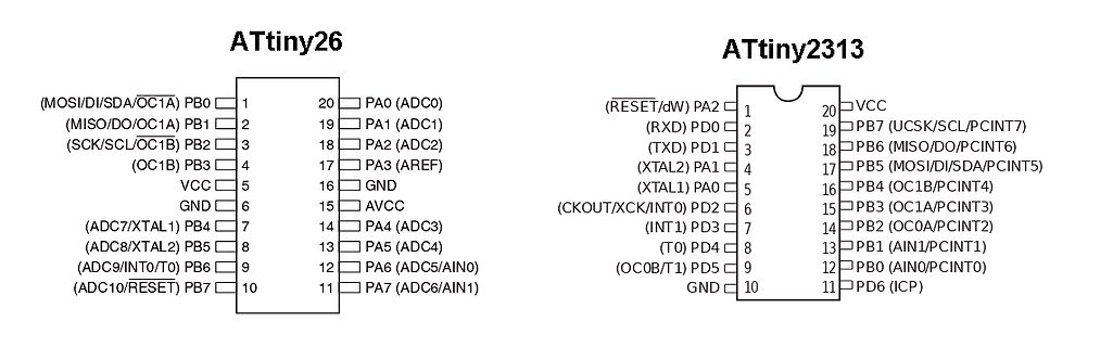
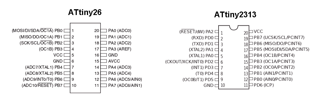
Pinbelegung ATtiny26 und ATtiny2313
ATtiny26 (MOSI/DI/SDA/OC1A) PB0 1 20 PA0 (ADC0) (MISO/DO/OC1A) PB1 2 19 PA1 (ADC1) (SCK/SCL/OC1B) PB2 3 18 PA2 (ADC2) (OC1B) PB3 4 17 PA3 (AREF) VCC 5 16 GND GND 6 15 AVCC (ADC7/XTAL1) PB4 7 14 PA4 (ADC3)
in „Suche Attiny26L-8SU (NOS)“ · Markt · · Screenshots
-
Bild
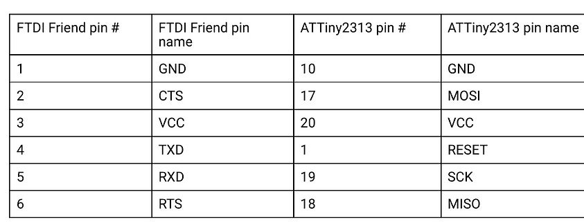
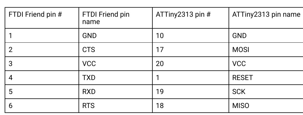
Pinbelegungstabelle FTDI Friend und ATTiny2313
FTDI Friend pin # | FTDI Friend pin name | ATTiny2313 pin # | ATTiny2313 pin name 1 | GND | 10 | GND 2 | CTS | 17 | MOSI 3 | VCC | 20 | VCC 4 | TXD | 1 | RESET 5 | RXD | 19 | SCK 6 | RTS | 18 | MISO
in „ATtiny13 Programmierung mit FT232R“ · Mikrocontroller und Digitale Elektronik · · Diagramme
-
Bild
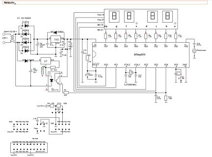
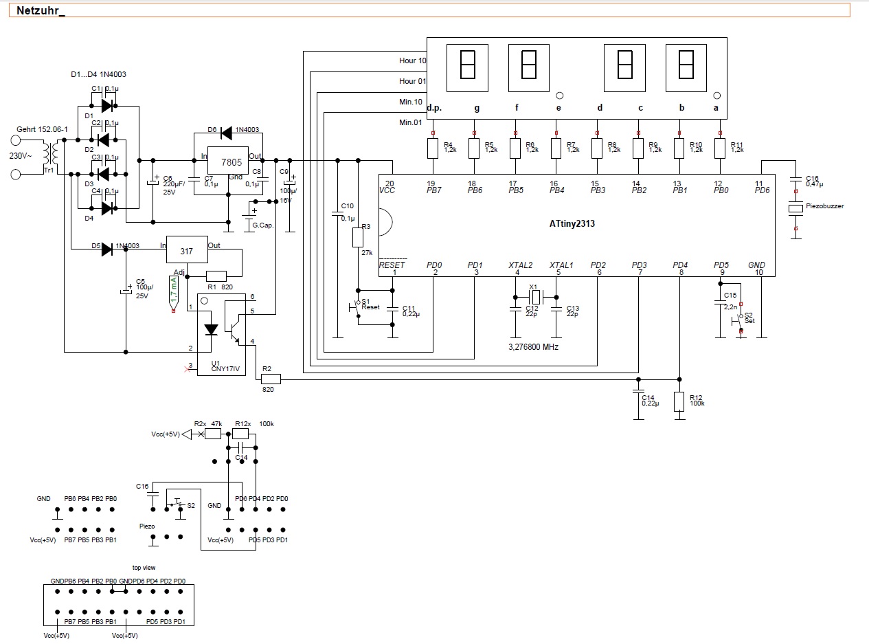
Schaltplan eines Netzteils mit ATtiny2313 und 7805
1N4003, 317, R1 820, U1 LM317, 7805, C9 0.1uF, C10 100uF, R3 27k, RESET, C11 0.22uF, X1 3.276800 MHz, ATtiny2313, PB7 bis PB0, PD0 bis PD5, GND, C12 22pF, C13 22pF, C14 0.22uF, C15 0.22uF, R12 100k, R2x 47k, R12x 100k, Piezo buzzer
in „Reparaturtips für VFD von alter Elektronika-Leuchte“ · Analoge Elektronik und Schaltungstechnik · · Schaltpläne
-
Bild
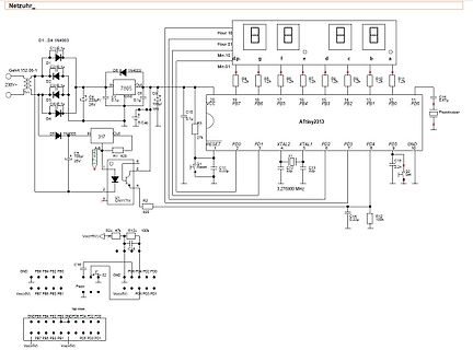
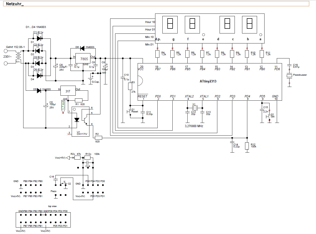
Schaltplan eines Netzteils mit ATtiny2313 Mikrocontroller
, 7805, C4 0.1uF, C5 100uF/25V, 317, R1 820, U1 LM317, R2 820, C6 0.1uF, RESET, X1 3.276800 MHz, ATtiny2313, R4 bis R11, C10 10uF, C12 22pF, C13 22pF, C14 0.22uF, C15 0.22uF, C16 0.47uF, Piezo buzzer, R12 100k, R2x 47k, R3 27k, Vcc(5V), GND
in „Reparaturtips für VFD von alter Elektronika-Leuchte“ · Analoge Elektronik und Schaltungstechnik · · Schaltpläne
-
Bild
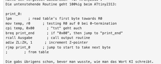
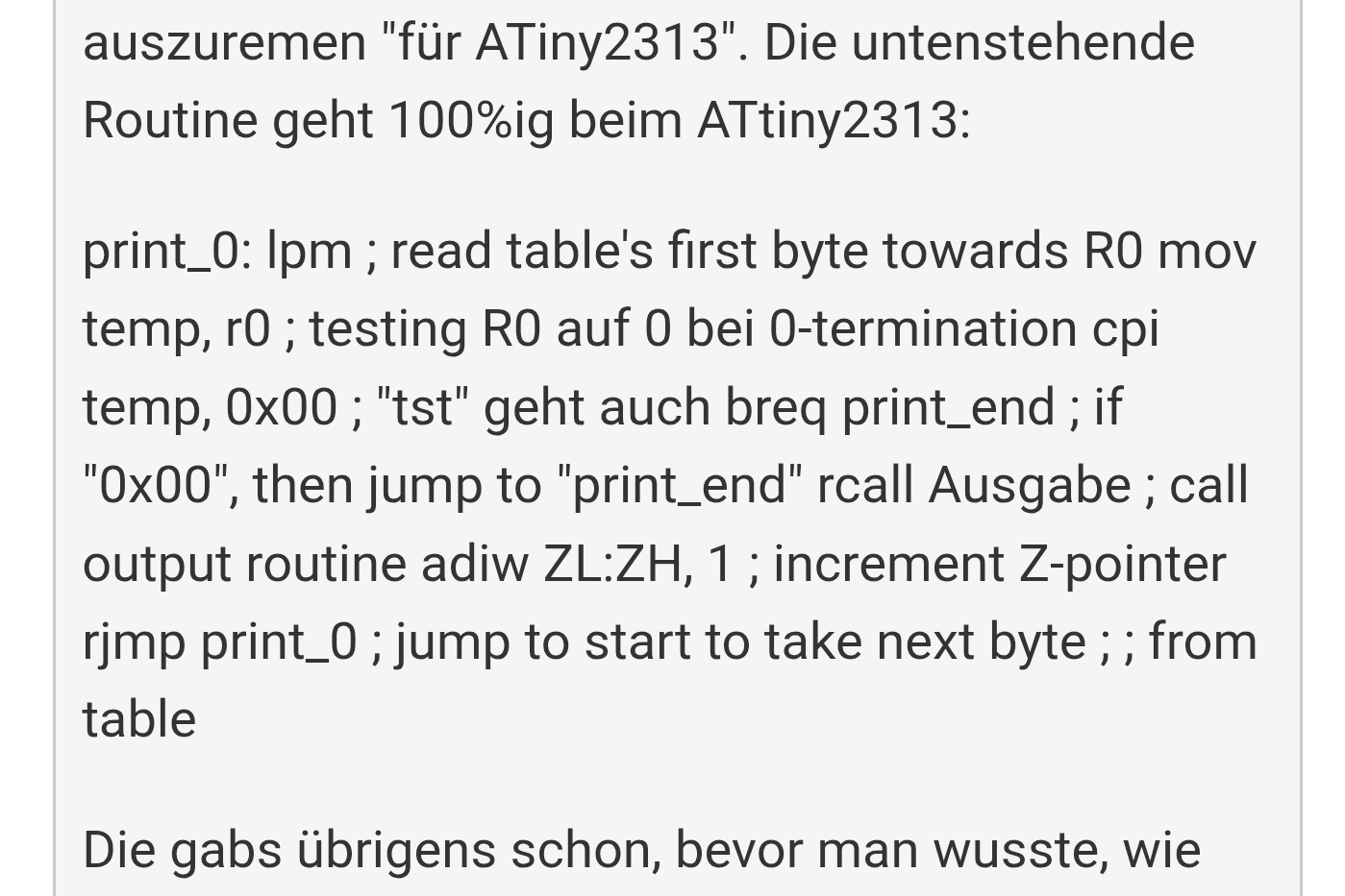
Assembler-Code für ATtiny2313
print_0: lpm ; read table's first byte towards R0 mov temp, r0 ; testing R0 auf 0 bei 0-termination cpi temp, 0x00 ; "tst" geht auch breq print_end ; if "0x00", then jump to "print_end" rcall Ausgabe ; call output routine adiw ZL:ZH, 1 ; increment Z-pointer rjmp print_0 ; jump to start to take next byte
in „I2C Display einfache Frage“ · Mikrocontroller und Digitale Elektronik · · Screenshots
-
Bild
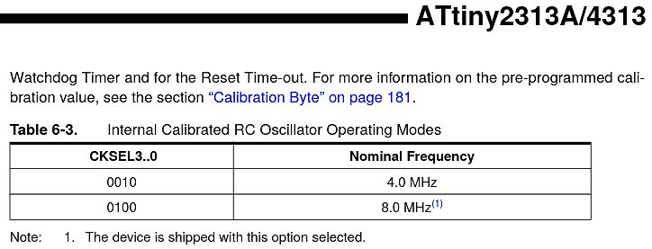
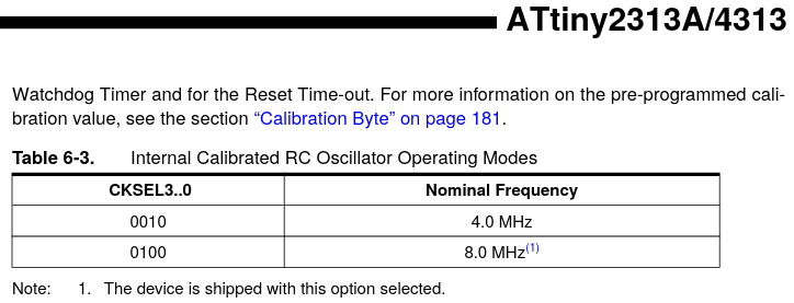
Tabellenausschnitt aus einem ATtiny2313A/4313 Datenblatt
ATtiny2313A/4313 Watchdog Timer and for the Reset Time-out. For more information on the pre-programmed calibration value, see the section "Calibration Byte" on page 181. Table 6-3. Internal Calibrated RC
in „ATTiny 2313-20PU und 2313A-PU“ · Mikrocontroller und Digitale Elektronik · · Screenshots
-
Bild
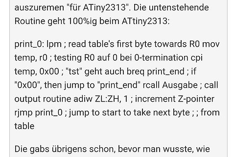
Text mit Assembler-Code für ATtiny2313
auszuremen "für ATtiny2313". Die untenstehende Routine geht 100%ig beim ATtiny2313: print_0: lpm ; read table's first byte towards R0 mov temp, r0 ; testing R0 auf 0 bei 0-termination cpi temp, 0x00 ; "tst" geht auch breq
in „I2C Display einfache Frage“ · Mikrocontroller und Digitale Elektronik · · Screenshots
-
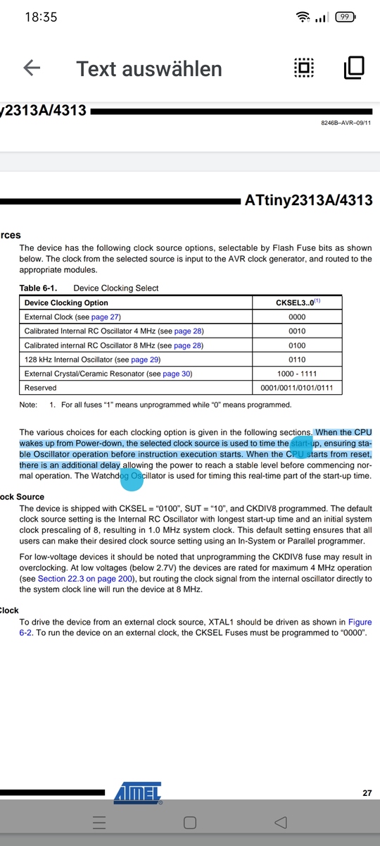
Bild
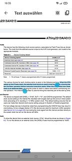
Ausschnitt aus einem Datenblatt eines ATtiny2313A Mikrocontrollers
ATtiny2313A/4313 Table 6-1. Device Clock Select Device Clocking Option | CKSEL3..0 External Clock | 0000 Calibrated Internal RC Oscillator 4 MHz | 0010 Calibrated Internal RC Oscillator 8 MHz | 0100 128 kHz
in „ATTiny 2313-20PU und 2313A-PU“ · Mikrocontroller und Digitale Elektronik · · Screenshots
-
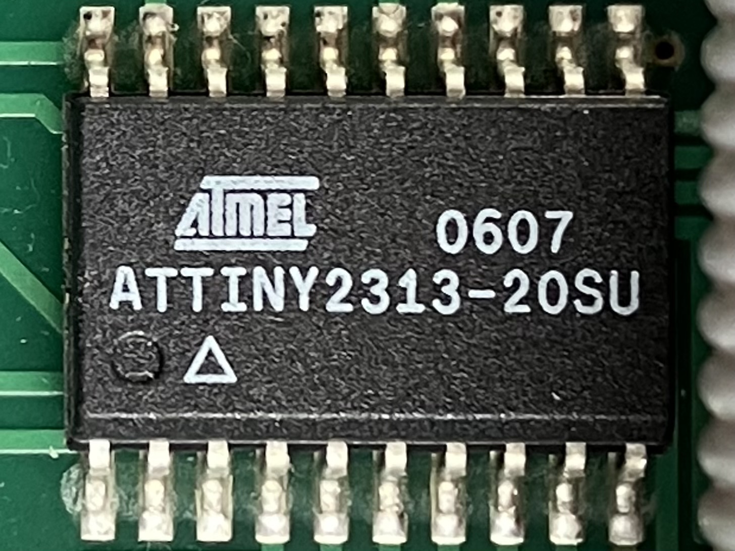
Bild
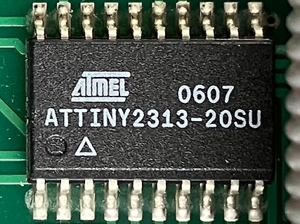
Atmel ATtiny2313-20SU Mikrocontroller auf Leiterplatte
ATMEL 0607 ATTINY2313-20SU
in „Hameg 8040-3 HF-Störungen“ · Analoge Elektronik und Schaltungstechnik · · Platinenfotos
-
PDF
doc4298.pdf
AVR091: Replacing AT90S2313 by ATtiny2313 Features 8-bit • AT90S2313 Errata Corrected in ATtiny2313 Changes to Bit and Register Names Microcontrollers Changes to Interrupt Vector Oscillators and Selecting Start-up Delays Improvements
in „tiny2313-90S2313“ · Mikrocontroller und Digitale Elektronik ·
-
PDF
Unterschied2313A.pdf
AVR533: Migrating from ATtiny2313 to ATtiny2313A 8-bit Microcontrollers 1 Introduction In order to optimize the manufacturing process and to further reduce current Application Note consumption, an optimized version of ATtiny2313
in „ATTiny2313A-Problem mit UART“ · Mikrocontroller und Digitale Elektronik ·
-
Datei
iotn2313.h
the new name in this case. The hardware interrupt vector table has changed from that of the AT90S2313. ATtiny2313 programs in page mode rather than the byte mode of the AT90S2313. Beware of programming the ATtiny2313 as a AT90S2313 device, when programming the Flash. ATtiny2313 has Signature Bytes: 0x1E 0x91 0x0A. Changes and/or additions are noted by "ATtiny" in the comments below. */ /* avr/iotn2313.h - definitions for ATtiny2313 */ #ifndef _AVR_IOTN2313_H_ #define _AVR_IOTN2313_H_ 1 /* This file should only be included from <avr/io.h>, never directly
in „ATtiny2313 Timer0 problem“ · Mikrocontroller und Digitale Elektronik ·
-
Datei
diff.txt
__) || defined (__AVR_ATtiny2313A__) 139a150,153 > #else > extern void TIMER0_OVF_vect (void); > extern void TIMER0_OVF_vect (void) > #endif 167a182 > #if defined (__AVR_ATtiny2313__) || defined (__AVR_ATtiny2313A__) 169a185,188
in „Reziproker Frequenzzähler+ Optimierte 64bit uint Routinen“ · Projekte & Code ·
-
PDF
Atiny2313.pdf
Programmable I/O Lines – 20-pin PDIP, 20-pin SOIC, 20-pad QFN/MLF Operating Voltages – 1.8 - 5.5V (ATtiny2313V) – 2.7 - 5.5V (ATtiny2313) Speed Grades – ATtiny2313V: 0 - 4 MHz @ 1.8 - 5.5V, 0 - 10 MHz @ 2.7 - 5.5V – ATtiny2313: 0 - 10 MHz @ 2.7 - 5.5V, 0 - 20 MHz @ 4.5 - 5.5V Typical Power Consumption
in „Suche tutorial“ · Mikrocontroller und Digitale Elektronik ·
-
PDF
TechnicalReference_ATmega32Board.pdf
verfälschen. Über die Portpins PC0 und PC1 ist der ATmega32 mit dem zweiten Mikrocontroller (einem ATtiny2313) auf der Platine über eine TWI Schnittstelle verbunden. Die Verbindung zum ATtiny2313 kann über den Jumper JP3 geöffnet werden, sofern in einem aufgebauten TWI Netzwerk der ATtiny2313 nicht benötigt
in „unbekanntes Board / Programmer ib-markl“ · Mikrocontroller und Digitale Elektronik ·
-
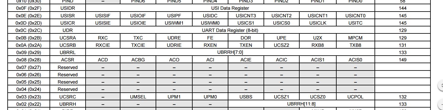
Bild
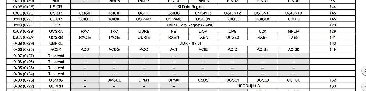
Registerbelegungstabelle eines Mikrocontrollers
USIDR, USISIF, USIOIF, USIPF, USIDC, USICNT3, USICNT2, USICNT0, USICR, USISIE, USIOIE, USIWM1, USIWM0, USICS1, USICS0, USICLK, USITC, UDR, UART Data Register (8-bit), UCSRA, RXC, TXC, UDRE, FE, UPE, U2X, MPCM, UCSRB, RXCIE, TXCIE, UDRIE, RXEN, TXEN, UCSZ2, RXB8, TXB8, UBRRL, UBRRH[7:0], ACSR, ACD, ACBG, ACO, ACI, ACIE, ACIC, ACIS1, ACIS0, UCSRC, UMSEL, UPM1, UPM0, USBS, UCSZ1, UCSZ0, UCPOL, UBRRH, UBRRH[11:8]
in „.hex Datei erzeugen“ · Mikrocontroller und Digitale Elektronik · · Screenshots
-
PDF
ATtiny2313.pdf
ATtiny2313.pdf
in „mein erstes avr-board“ · Mikrocontroller und Digitale Elektronik ·
-
PDF
ATtiny2313.pdf
ATtiny2313.pdf
in „mein erstes avr-board“ · Mikrocontroller und Digitale Elektronik ·
-
PDF
ATtiny2313.pdf
ATtiny2313.pdf
in „mein erstes avr-board“ · Mikrocontroller und Digitale Elektronik ·
-
PDF
ATtiny2313.pdf
ATtiny2313.pdf
in „mein erstes avr-board“ · Mikrocontroller und Digitale Elektronik ·
-
Datei
attiny2313.bas
'------------------------------------------------------------------------------- 'Regfile für Attiny 2313 $regfile = "attiny2313.dat" '------------------------------------------------------------------------------- 'Ausgänge und Eingänge definieren und konfigurieren. 'Interrupt auf PIND.2 Config Portb
in „Attiny2313 Herz - Interrupt Problem“ · Mikrocontroller und Digitale Elektronik ·
-
Datei
attiny2313.c
/******************************************************* Projekt: DP Lüftersteuerung Version : ATTiny2313A - 1 Erstellt: 22.10.2016 Letze Änderung: 24.10.2016 Chip: Attiny2313A mit internen 8.0 MHz *******************************************************/ /// Header-Dateien /// #include <io.h> #include <delay.h> /// #define /// // Kommunikation (Daten vom Attiny25 empfangen) #define InterruptIn PIND.2 #define DataIn PINA.0 //7-Segment-Anzeigen #define SegmentA PORTB.7 #define SegmentB PORTB.6 #define SegmentC PORTB.5 #define SegmentD PORTB.4 #define SegmentE
in „Attiny2313A - Timer Interrupt wird nicht aufgerufen (C)“ · Mikrocontroller und Digitale Elektronik ·
-
PDF
STK200.pdf
ATmega169 DEVICE SOCKET DEVICE SOCKET DEVICE SOCKET ISP supportonly- AT90S1200 20D ATmega48 28D ATtiny26 20A boardsupporton STK300: AT90S2313 20D ATmega88 28D ATtiny2313 20D AT90S2323 8D ATmega168 28D ATtiny12 8D ATmega103 AT90S2343 8D ATmega8 28D ATtiny13 8D ATmega128 AT90S2333 28D ATmega16 40A ATtiny15
in „Wer kennt dieses AVR-Board?“ · Mikrocontroller und Digitale Elektronik ·
-
Datei
log.txt
/nix' avr-gcc -c -mmcu=attiny2313 -I. -gstabs -DF_CPU=16000000UL -Os -Wall -Wextra -W strict-prototypes -std=gnu99 -funsigned-char -funsigned-bitfields -fpack-struct -fshort-enums -ffunction-sections ../main.c -o main.o ../main.c
in „Bitte um Hilfe bei Code-Optimierung“ · Mikrocontroller und Digitale Elektronik ·
-
Datei
x.txt
atmega88pa atmega8a atmega8hva atmega8u2 atmxt112sl atmxt224 atmxt224e atmxt336s atmxt540s atmxt540sreva attiny11 attiny12 attiny13 attiny13a attiny15 attiny1634 attiny167 attiny22 attiny2313 attiny2313a attiny24 attiny24a attiny25 attiny26 attiny261 attiny261a attiny28 attiny4313 attiny43u attiny44 attiny44a
in „Eclipse (mars) und AVR -- Fehlermeldungen“ · Mikrocontroller und Digitale Elektronik ·
-
Datei
USI_TWI_Master.h
* * Supported devices : All device with USI module can be used. * The example is written for the ATtiny2313 * * AppNote : AVR310 - Using the USI module as a TWI Master * * This is modified to just do I2C communication on ATtiny2313 running at * 1MHz. Fast mode is probably possible, but would need a faster
in „Attin84 I2C mit der USI läuft nicht“ · Mikrocontroller und Digitale Elektronik ·
-
Datei
mlib-gen-3.diff
(HAS_attiny2313, test "x$HAS_attiny2313" = "xyes") - -CHECK_AVR_DEVICE(attiny2313a) -AM_CONDITIONAL(HAS_attiny2313a, test "x$HAS_attiny2313a" = "xyes") - -CHECK_AVR_DEVICE(attiny24) -AM_CONDITIONAL(HAS_attiny24
in „Fork: avr-libc version 3, für xtiny“ · Mikrocontroller und Digitale Elektronik ·
-
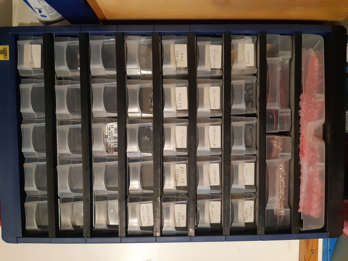
Bild
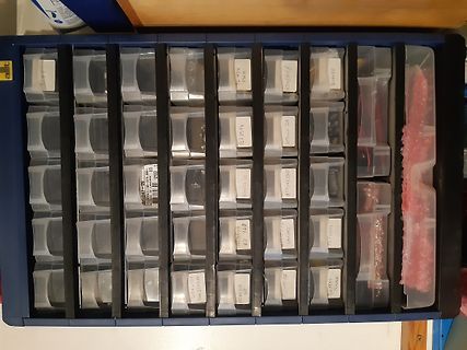
Sortierbox mit elektronischen Bauteilen
ATmega8 ATtiny25 ATtiny26 ATtiny45 ATtiny85 ATtiny13 ATtiny84 ATtiny2313 ATtiny44 ATtiny27 ATtiny45 ATtiny85 ATtiny25 ATtiny26 ATtiny45 ATtiny85 ATtiny13 ATtiny84 ATtiny2313 ATtiny44 ATtiny27 ATtiny45 ATtiny85 ATtiny25 ATtiny26 ATtiny45 ATtiny85 ATtiny13 ATtiny84 ATtiny2313 ATtiny44 ATtiny27
in „Nachlassauflösung, AVRs, Oszi, MM, Bücher, div. Bauteile“ · Markt · · Fotos
-
Datei
spi_uart.c
AVR_ATmega16__ SPCR = _BV(SPE); #endif #ifdef __AVR_ATmega8515__ SPCR = _BV(SPE); #endif #ifdef __AVR_ATtiny2313__ USICR = _BV(USIWM0) | _BV(USICS1) | _BV(USICLK) | _BV(USITC); // 3 Wire Mode USISR = _BV(USIOIF); // Clear Overflow flag #endif } /** Senden per Interrupt */ #if defined __AVR_AT90S2313__ //SIGNAL
in „SPI, Wie SPDR Empty erkennen“ · Mikrocontroller und Digitale Elektronik ·
-
Datei
dumpspecs1.txt
sysroot_suffix_spec: *sysroot_hdrs_suffix_spec: *crt_binutils: %{mmcu=at90s1200|mmcu=avr1:crts1200.o%s} %{mmcu=attiny11:crttn11.o%s} %{mmcu=attiny12:crttn12.o%s} %{mmcu=attiny15:crttn15.o%s} %{mmcu=attiny28:crttn28.o%s} %{!mmcu*|mmcu=at90s8515|mmcu=avr2:crts8515.o%s} %{mmcu=at90s2313:crts2313.o%s} %{mmcu=at90s2323
in „ATtiny24 - ISR wird nie gerufen __vectors> fehlt“ · Mikrocontroller und Digitale Elektronik ·
-
PDF
Bitwackler.pdf
artlist, die Angabe, die –p folgt bestimmt, welchen Chip AVRDUDE flashen soll Hier gegeben für einen ATtiny2313: -p t2313 Beispiel für einen ATMega8: -p m8 Beispiel für einen ATMega168: -p m168 -c zu verwendender Programmer Hier gegeben: -c ponyser Beispiel für Programmer USBtinyISP: -c usbtiny Beispiel
in „Zeigt her eure "Grottenwerke"“ · Mikrocontroller und Digitale Elektronik ·
-
PDF
D810038B.PDF
644 • IC-Sockel DIP 28 für den MicrocontrollerATmega 8 • IC-Sockel DIP 20 für den MicrocontrollerATtiny 2313 • z wei IC-Sockel DIP 8 einmal für die MicrocontrollerATtiny 12 undATtiny 15 und zum anderen für I2C Eeproms der 24Cxx-Serie • RS232-Schnittstelle (Tx, Rx) mit Pegelanpassung über MAX232 • ein

-
PDF
D810038B.PDF
644 • IC-Sockel DIP 28 für den MicrocontrollerATmega 8 • IC-Sockel DIP 20 für den MicrocontrollerATtiny 2313 • z wei IC-Sockel DIP 8 einmal für die MicrocontrollerATtiny 12 undATtiny 15 und zum anderen für I2C Eeproms der 24Cxx-Serie • RS232-Schnittstelle (Tx, Rx) mit Pegelanpassung über MAX232 • ein
in „LCD Fusebits für Atmega32“ · Mikrocontroller und Digitale Elektronik ·
-
PDF
Pollin_AVR_Evalutationsboard.pdf
644 • IC-Sockel DIP 28 für den MicrocontrollerATmega 8 • IC-Sockel DIP 20 für den MicrocontrollerATtiny 2313 • z wei IC-Sockel DIP 8 einmal für die MicrocontrollerATtiny 12 undATtiny 15 und zum anderen für I2C Eeproms der 24Cxx-Serie • RS232-Schnittstelle (Tx, Rx) mit Pegelanpassung über MAX232 • ein
in „External Interrupt Atmega16“ · Mikrocontroller und Digitale Elektronik ·
-
PDF
Pollin_Atmel_Evaluationsboard_2.0.1.pdf
644 • IC-Sockel DIP 28 für den MicrocontrollerATmega 8 • IC-Sockel DIP 20 für den MicrocontrollerATtiny 2313 • z wei IC-Sockel DIP 8 einmal für die MicrocontrollerATtiny 12 undATtiny 15 und zum anderen für I2C Eeproms der 24Cxx-Serie • RS232-Schnittstelle (Tx, Rx) mit Pegelanpassung über MAX232 • ein
in „suche PDF zu einem älteren Pollin Eval. Board“ · Mikrocontroller und Digitale Elektronik ·
-
PDF
D810074B.pdf
644 • IC-Sockel DIP 28 für den MicrocontrollerATmega 8 • IC-Sockel DIP 20 für den MicrocontrollerATtiny 2313 • z wei IC-Sockel DIP 8 einmal für die MicrocontrollerATtiny 12 undATtiny 15 und zum anderen für I2C Eeproms der 24Cxx-Serie • RS232-Schnittstelle (Tx, Rx) mit Pegelanpassung über MAX232 • ein
in „Probleme beim Einstieg in die wunderbare Welt der Microcontroller“ · Mikrocontroller und Digitale Elektronik ·
-
PDF
Evaluationsboard.PDF
644 • IC-Sockel DIP 28 für den MicrocontrollerATmega 8 • IC-Sockel DIP 20 für den MicrocontrollerATtiny 2313 • z wei IC-Sockel DIP 8 einmal für die MicrocontrollerATtiny 12 undATtiny 15 und zum anderen für I2C Eeproms der 24Cxx-Serie • RS232-Schnittstelle (Tx, Rx) mit Pegelanpassung über MAX232 • ein
in „Atmega16 UART empfängt nicht - senden klappt“ · Mikrocontroller und Digitale Elektronik ·
-
PDF
Unterlagen_Pollinboard.pdf
644 • IC-Sockel DIP 28 für den MicrocontrollerATmega 8 • IC-Sockel DIP 20 für den MicrocontrollerATtiny 2313 • z wei IC-Sockel DIP 8 einmal für die MicrocontrollerATtiny 12 undATtiny 15 und zum anderen für I2C Eeproms der 24Cxx-Serie • RS232-Schnittstelle (Tx, Rx) mit Pegelanpassung über MAX232 • ein
in „Atmega16 keine Kommunikation“ · Mikrocontroller und Digitale Elektronik ·
-
Datei
uart_printf.c
AVR-MCU. Protokoll 8N1 Controller mit Hardware-UART - ATmega8 - ATmega8515 - ATmega48 - ATmega328 - ATtiny2313, ATtiny4313 Controller mit USI-Serial - ATtiny24 - ATtiny84 - ATtiny25 - ATtiny85 Anschlussbelegungen: MCU PORT Funk.1 Funk.2 --------------------------------------------------- ATtiny25 - ATtiny85
in „Ausgabe mittels printf über UART für ATmega / ATtiny“ · Projekte & Code ·
-
PDF
Preview_of__io.h_.pdf
defined (__AVR_ATtiny10__) # include <avr/iotn10.h> #elif defined (__AVR_ATtiny20__) # include <avr/iotn20.h> #elif defined (__AVR_ATtiny40__) # include <avr/iotn40.h> #elif defined (__AVR_ATtiny2313__) # include <avr/iotn2313.h> #elif defined (__AVR_ATtiny2313A__) # include <avr/iotn2313a.h> #elif defined (__AVR_ATtiny13__) # include <avr/iotn13.h> Page 6 of 9 io.h 24.07.12 15:37 #elif defined (__AVR_ATtiny13A__) # include <avr/iotn13a.h> #elif defined
in „µC am Mac mit C programmieren“ · Mikrocontroller und Digitale Elektronik ·
-
PDF
TSL230_ReadMe_110717.pdf
Messung der Beleuchtungsstärke mit TSL230 und ATtiny2313 in C Messung der Beleuchtungsstärke mit Light-to-Frequency-Converter TSL230R und ATtiny2313 in C 1.) Allgemeines Der Light_To_Frequency-Converter TSL230 erzeugt an seinem Ausgangspin einen Takt
in „Messung der Beleuchtungsstärke mit TSL230R und ATtiny2313 in C“ · Projekte & Code ·
-
PDF
Atmel_Evaluations-Board_Version_2.0.pdf
drei verschiede- ne Möglichkeiten: Die Microcontroller ATmega8535, ATmega16, ATmega32, Atmega8, Attiny 2313, Attiny12 und Attiny15 können über die ISP-Schnittstelle programmiert werden, indem sie über die serielle Schnittstelle mit dem PC verbunden werden, oder über einen ISP- Schnittstellenadapter,
in „ISP über RS232“ · Mikrocontroller und Digitale Elektronik ·
-
PDF
D810038B.PDF
drei verschiede- ne Möglichkeiten: Die Microcontroller ATmega8535, ATmega16, ATmega32, Atmega8, Attiny 2313, Attiny12 und Attiny15 können über die ISP-Schnittstelle programmiert werden, indem sie über die serielle Schnittstelle mit dem PC verbunden werden, oder über einen ISP- Schnittstellenadapter,
in „Pollin Board unzuverlässig-Hilfe bei der Fehlersuche!“ · Mikrocontroller und Digitale Elektronik ·
-
PDF
Pollin_Board.pdf
drei verschiede- ne Möglichkeiten: Die Microcontroller ATmega8535, ATmega16, ATmega32, Atmega8, Attiny 2313, Attiny12 und Attiny15 können über die ISP-Schnittstelle programmiert werden, indem sie über die serielle Schnittstelle mit dem PC verbunden werden, oder über einen ISP- Schnittstellenadapter,
in „AVR: UART Pollin Board“ · Mikrocontroller und Digitale Elektronik ·
-
PDF
D810038B.pdf
drei verschiede- ne Möglichkeiten: Die Microcontroller ATmega8535, ATmega16, ATmega32, Atmega8, Attiny 2313, Attiny12 und Attiny15 können über die ISP-Schnittstelle programmiert werden, indem sie über die serielle Schnittstelle mit dem PC verbunden werden, oder über einen ISP- Schnittstellenadapter,
-
PDF
AVR-Board20_810038B.PDF
drei verschiede- ne Möglichkeiten: Die Microcontroller ATmega8535, ATmega16, ATmega32, Atmega8, Attiny 2313, Attiny12 und Attiny15 können über die ISP-Schnittstelle programmiert werden, indem sie über die serielle Schnittstelle mit dem PC verbunden werden, oder über einen ISP- Schnittstellenadapter,
in „Atmel Evaluationboard V2.01“ · Mikrocontroller und Digitale Elektronik ·
-
PDF
pollin_board.PDF
drei verschiede- ne Möglichkeiten: Die Microcontroller ATmega8535, ATmega16, ATmega32, Atmega8, Attiny 2313, Attiny12 und Attiny15 können über die ISP-Schnittstelle programmiert werden, indem sie über die serielle Schnittstelle mit dem PC verbunden werden, oder über einen ISP- Schnittstellenadapter,
in „Atmega32 Evaluationsboard pollin mysmartusb“ · Mikrocontroller und Digitale Elektronik ·
-
PDF
D810038b_3.pdf
drei verschiede- ne Möglichkeiten: Die Microcontroller ATmega8535, ATmega16, ATmega32, Atmega8, Attiny 2313, Attiny12 und Attiny15 können über die ISP-Schnittstelle programmiert werden, indem sie über die serielle Schnittstelle mit dem PC verbunden werden, oder über einen ISP- Schnittstellenadapter,
in „richtige Hard und Software für Anfänger“ · Mikrocontroller und Digitale Elektronik ·
-
PDF
pollin_board.PDF
drei verschiede- ne Möglichkeiten: Die Microcontroller ATmega8535, ATmega16, ATmega32, Atmega8, Attiny 2313, Attiny12 und Attiny15 können über die ISP-Schnittstelle programmiert werden, indem sie über die serielle Schnittstelle mit dem PC verbunden werden, oder über einen ISP- Schnittstellenadapter,
in „Interrupt und PortC Atmega32“ · Mikrocontroller und Digitale Elektronik ·
-
PDF
Beschreibung_ATMEL_Evaluations-Board_Ver_2_0_1_von_Pollin_D810038B.pdf
644 • IC-Sockel DIP 28 für den MicrocontrollerATmega 8 • IC-Sockel DIP 20 für den MicrocontrollerATtiny 2313 • zwei IC-Sockel DIP 8 einmal für die MicrocontrollerATtiny 12 undATtiny 15 und zum anderen für I2C Eeproms der 24Cxx-Serie • RS232-Schnittstelle (Tx, Rx) mit Pegelanpassung über MAX232 • ein
in „AMTEL Evaluationsboard 2.0.1 von Pollin“ · Mikrocontroller und Digitale Elektronik ·