MPX-demodulator outputs • Internal voltage stabilization. QUICK REFERENCE DATA SYMBOL PARAMETER MIN. TYP. MAX. UNIT VP supply voltage (pin 5) 7.5 10 12 V I supply current − 12 − mA P Vo(rms) audio output signal (RMS value) − 900 − mV THD total harmonic distortion − 0.1 0.3 % S/N signal-to-noise ratio − 76 −
der Rückkopplung. Den könnte man sicher entfernen, wenn man mehr Bandbreite will. Ansonsten ist der MAX4466 ohnehin kein Geschwindigkeitswunder mit seinen 200 bzw. 600kHz GBWP. Bei geschätzt 50-facher Verstärkung limitiert das schon gewaltig den normalen Hörbereich, da wird man keine scharfe Schaltflanken
endgültigen Erfolg geführt haben: Als Mikrophon verwendete ich ein kleines Elektret-Mikrofon mit Verstärker MAX4466. Die Verstärkung ist einstellbar. Es wird preiswert und in großen Serien produziert. In der Standuhr wurde es an einer kleinen Leiste montiert und mit Doppelklebefolie am Uhrwerk in der Nähe des
specification 2 Remote 8-bit I/O expander for I C-bus PCF8574 SYMBOL PARAMETER CONDITIONS MIN. TYP. MAX. UNIT I/Os VIL LOW level input voltage −0.5 − +0.3VDD V VIH HIGH level input voltage 0.7VDD − VDD + 0.5 V IHL(max) maximum allowed input VI≥ VDD or I ≤ SS − − ±400 A current through protection diode
0 V; T = −40 to +85 °C; unless otherwise specified. DD SS amb SYMBOL PARAMETER CONDITIONS MIN. TYP. MAX. UNIT Supplies V supply voltage 2.5 − 5.5 V DD DD supply current operating mode; no load;− 100 200 A V = V or V ; I DD SS fSCL= 400 kHz DD(stb) standby current standby mode; no load; − 2.5 10 A V I
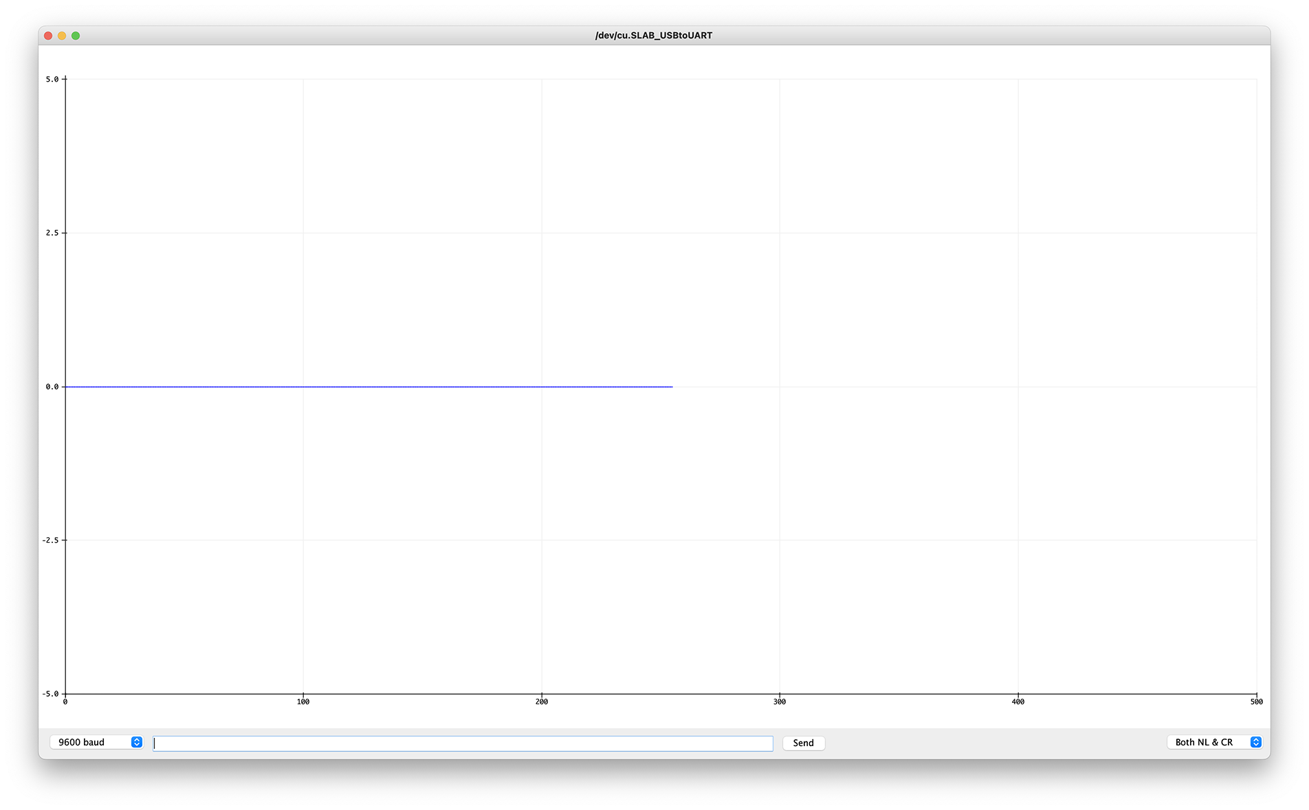
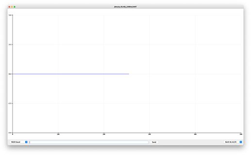
Alles klar. Ohne MAX4466 bekomme ich 256 schöne Nullen vom ADC. ADC pin A0 an GND.
MAX4466 breakout boards bei fast absoluter Stille zu tun. Irgendetwas oszilliert da, aber warum kann ich natürlich nicht beurteilen. Vielleicht ist das bei diesen low-end breakout boards im alleruntersten
Semiconductors Product specification NPN power transistors BD135; BD137; BD139 FEATURES PINNING • High current (max. 1.5 A) PIN DESCRIPTION • Low voltage (max. 80 V). 1 emitter 2 collector, connected to metal part of APPLICATIONS mounting surface 3 base • Driver stages in hi-fi amplifiers and television circuits.
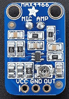
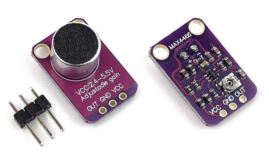
Hallo Community, hier liegt ein Elektret-Mikrofon MAX4466 für Arduinos rum (https://www.makershop.de/module/audio/adafruit-max4466/). Die Platine hat bei 3,3V einen Spannungsausgang von +- V/2, gibt bei perfekter Stille also 1,65V aus und steigt/fällt
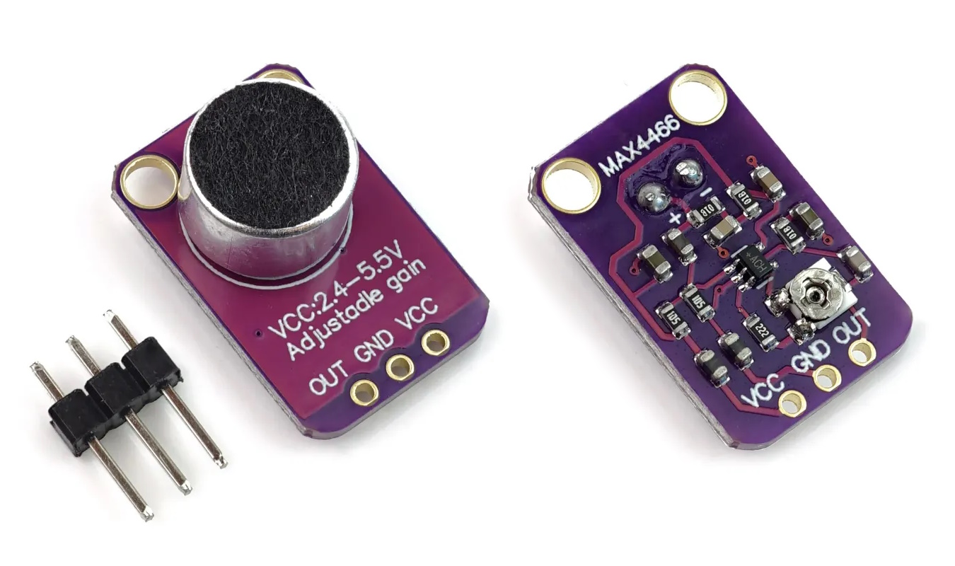
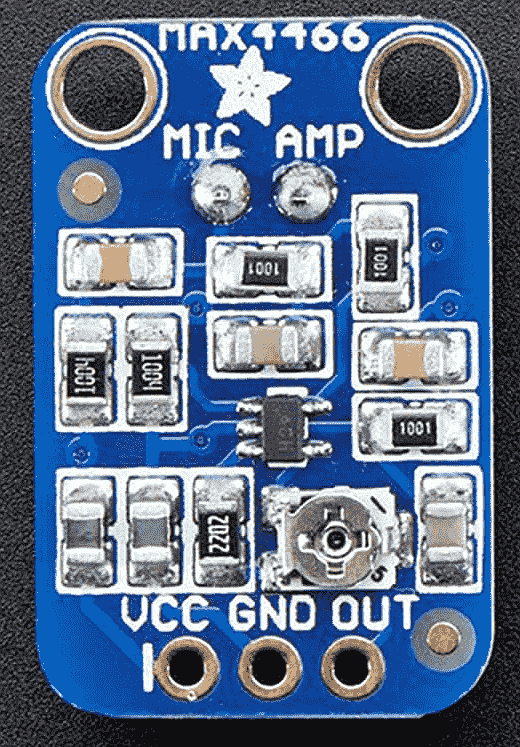
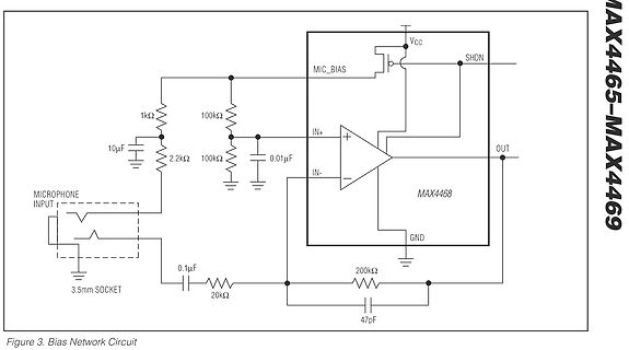
Auf der Platinenunterseite steht MAX4466 https://www.analog.com/media/en/technical-documentation/data-sheets/MAX4465-MAX4469.pdf https://www.analog.com/en/products/max4466.html Eine Klemmdiode wäre noch eine Möglichkeit, im Videobereich
A1T Zwischenstecker fiept" schreiben Spinner? Zurück zum Thema. Ich habe noch ESP32 hier und GY-MAX4466 aus einem anderen Projekt. Vielleicht geht das ja irgendwie am liebsten mit Tasmota. Dann könnte man es in die Influxdb loggen.
versuche das Video zu erklären. Das Video ist ca 14 Sekunden lang. Das Gerät ist ein iPhone 15 Pro Max. Auf der X-Achse ist die Frequenz und auf der Y-Achse die dB abgebildet. Das Video habe ich heute um 13:33Uhr aufgenommen in der Wohnung. Fast die gesamte Zeit ist die Frequenz mit ca 20Hz die lauteste
anschließend singend/pfeiffend/summend ebendiese Zielfrequenz treffen. Das verwendete Mikro ist ein MAX4466, die FFT Funktion ist für meine Zwecke hinreichend genau. Ferner ist es problemlos möglich das ganze auf dem LCD Display anzuzeigen. Die gewünschte Erweiterung des ganzen, war den Frequenzpegel nicht nur als Zahl, sondern auch als Linienpegel auf einer 9x9 Dotmatrix mit MAX7219 Modul darzustellen. Ab diesem Zeitpunkt kollabiert das Projekt. Von einem Offsetfehlers meiner Frequenz um 600Hz bis zur schlichten Nichtansteuerbarkeit der Matrix bei gleichzeitiger Zerstörung
Philips Semiconductors Product specification PNP power transistor BD330 FEATURES PINNING • High current (max. 3 A) PIN DESCRIPTION • Low voltage (max. 20 V). 1 emitter 2 collector, connected to metal part of APPLICATIONS mounting surface 3 base • Powerswitchingandamplification,especiallyinportable equipment
Philips Semiconductors Product specification NPN power transistor BD329 FEATURES PINNING • High current (max. 3 A) PIN DESCRIPTION • Low voltage (max. 20 V). 1 emitter 2 collector, connected to metal part of APPLICATIONS mounting surface 3 base • Especially for battery equipped applications. DESCRIPTION handbook
(at Recommended Operating Conditions) Symbol Parameter Min Typ Max Units Comment ISA bus (including PROHIBIT, BPD#) VIL Input Low Voltage 0.8 V TTL Level Inputs VIH Input High Voltage 2.0 V TTL Level Inputs VOL Output Low Voltage 0.5 V Iol=12 mA VOH Output High Voltage
Ausgängen besorgen: SDG2042X als Beispiel. Der [[FY6900]] kann das auch und ist sehr preiswert. Jitter max. 4ns, denn das Ding läuft intern mit 250MHz. Frequenzauflösung 1uHz!
Fehler. Mit solchen Angaben habe ich immer Probleme. Zudem sind für Dich eher die ppb interessant. Max. 70 ps Jitter bei 100 ns sind nun nicht gerade wenig. Auch auf den 2. Blick macht mich das Teil nicht an. Falk B. schrieb im Beitrag #7436840: > Der FY6900 kann das auch und ist sehr preiswert.
Semiconductors Product specification NPN general purpose transistor BC337 FEATURES PINNING • High current (max. 500 mA) PIN DESCRIPTION • Low voltage (max. 45 V). 1 emitter 2 base APPLICATIONS 3 collector • General purpose switching and amplification, e.g. driver and output stages of audio amplifiers. handbook
Projekt. Das Projekt war ein Musik-Spektrum-Analysator. Mit 464 WS2812B adressierbaren LEDs. Einem MAX4466 Mikrofon. Und als Mikrocontroller wurde ein EK-TM4C123GXL (Cortex M4F) von TI verwendet. Nun bin ich dabei, das Projekt zu optimieren. Dabei ist mir das Mikrofon mit dem starken Rauschen aufgefallen
Kevin H. schrieb im Beitrag #7393987: > Einem MAX4466 Mikrofon. > Dabei ist mir das Mikrofon mit dem starken Rauschen aufgefallen. Also ein Elektred am 4466 sollte nicht relevant rauschen. Schliess mal das Mikro kurz, rauscht es immer noch
NeoPixelBus-Bibliothek (https://github.com/Makuna/NeoPixelBus) über I2S und DMA angesteuert. Elektret-Module mit MAX4466 und MAX9814 sind vorhanden. Einzelne Elektret-Mikrofonkapseln und NE567D sind im Zulauf. Gibt es noch andere Optionen? Der ADC des ESP8266 scheint ungeeignet zu sein, da er bei aktivem WLAN
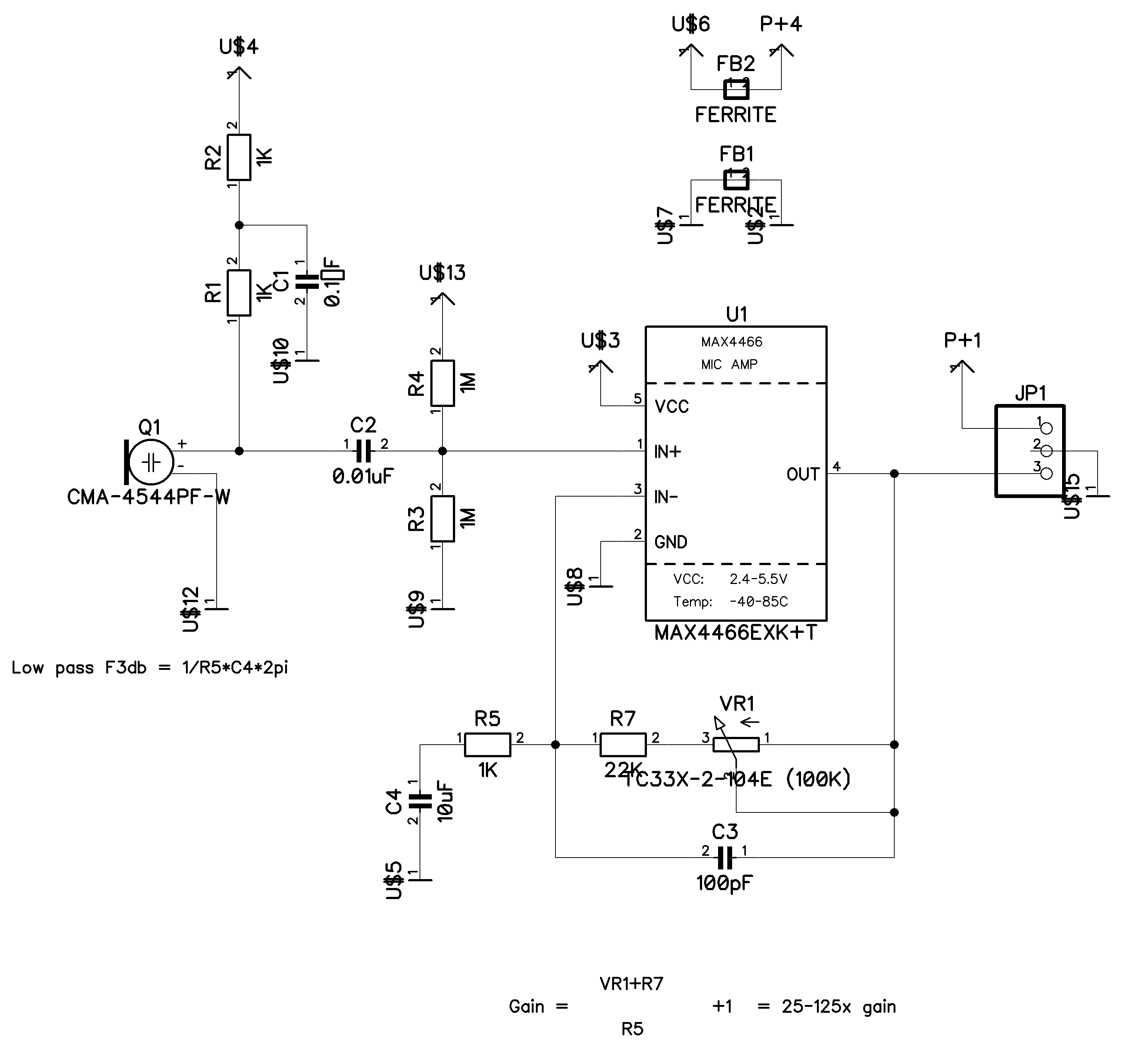
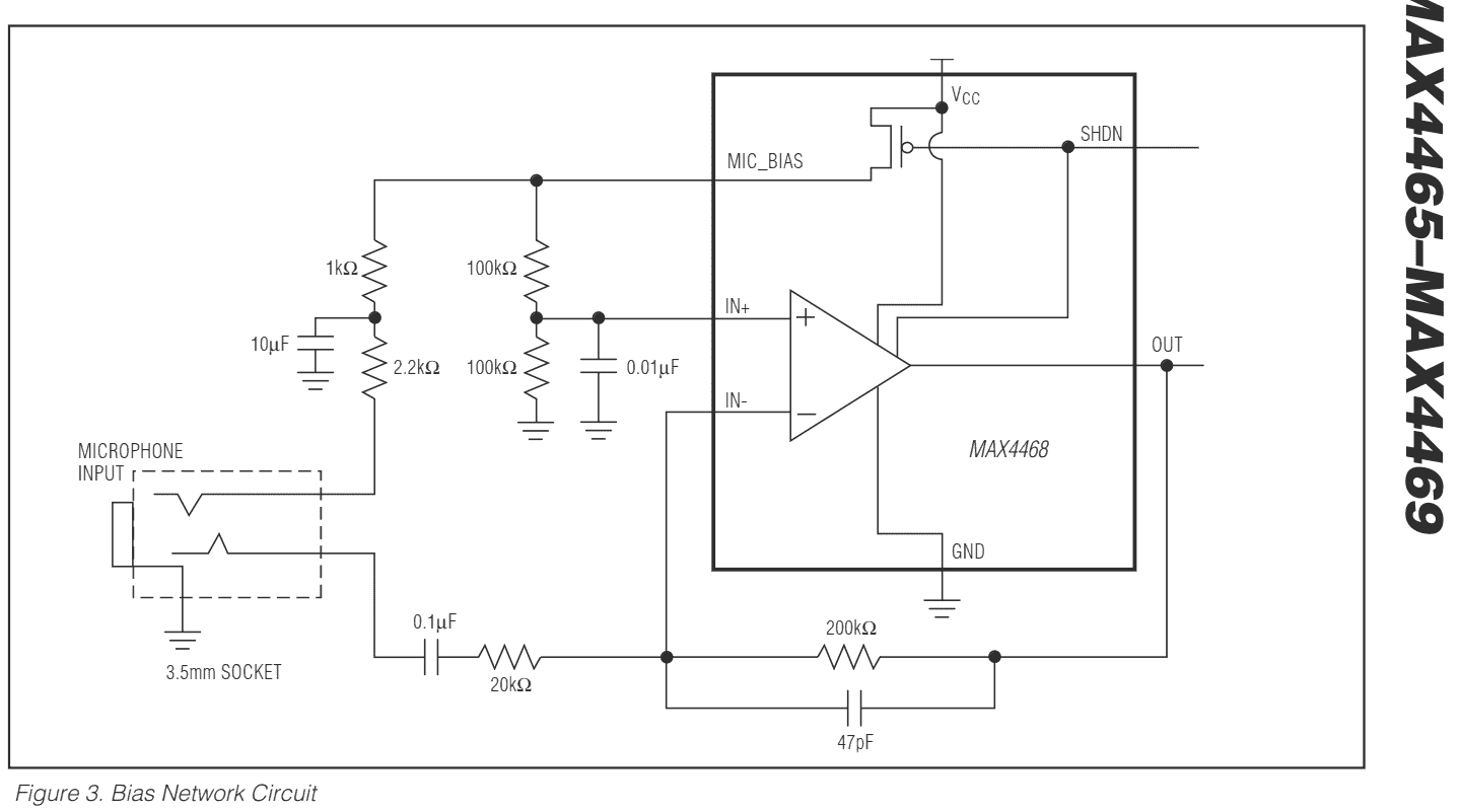
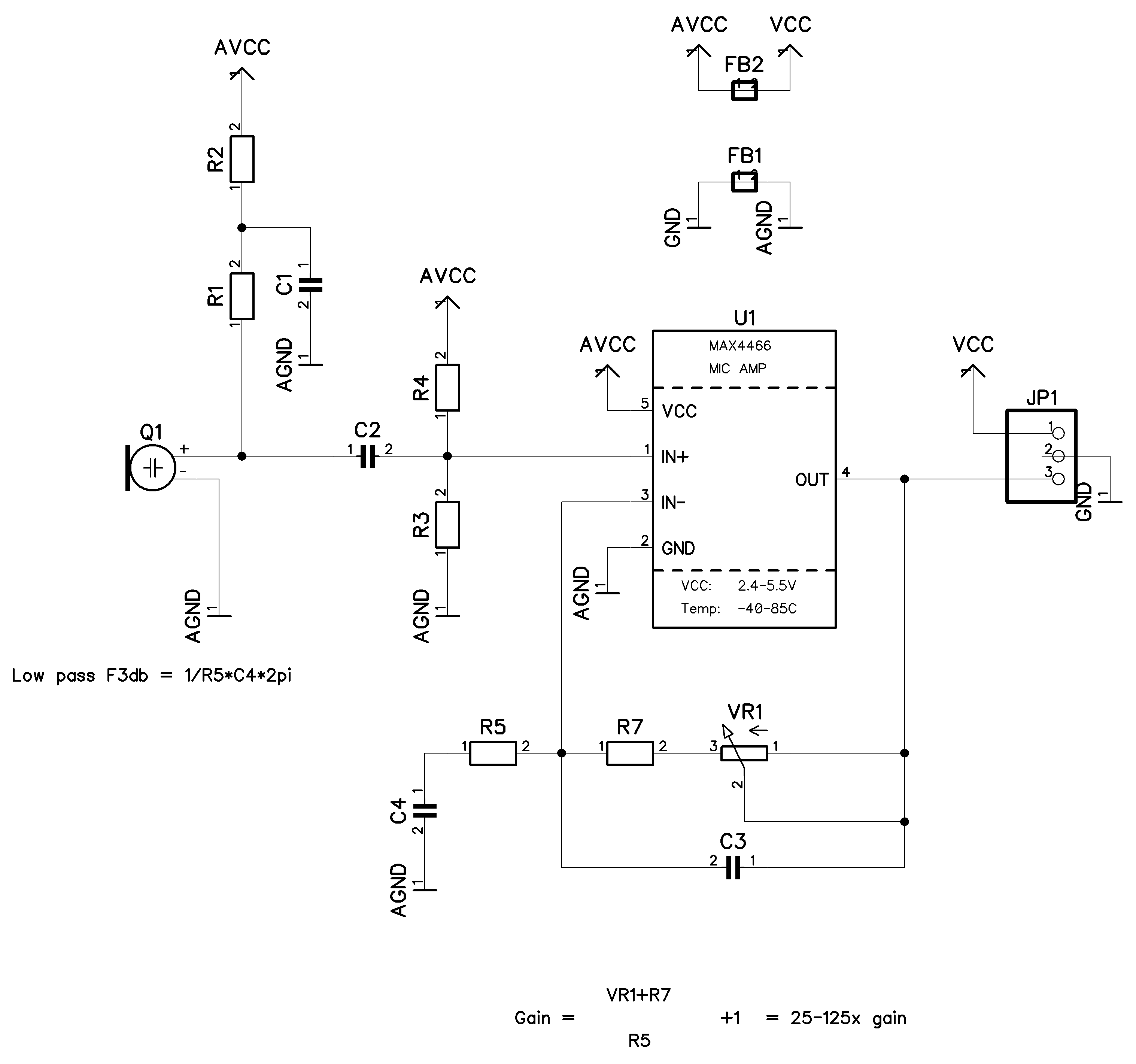
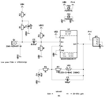
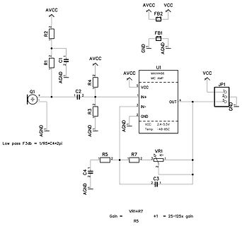
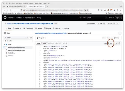
scheint aber der zu geringe Eingangspegel der Kapsel gewesen zu sein. Ich habe jetzt stattdessen ein MAX4466-Elektret-Mikrofonmodul (Schaltplan ähnlich https://github.com/adafruit/Adafruit-MAX4466-Electret-Mic-Amplifier-PCBs/blob/master/Adafruit%20MAX4466%20Mic%20Amp.sch) über 1nf an Pin 3 angeschlossen
specification Silicon diffused power transistors BUW84; BUW85 MGB938 handbook, full pagewidth 10 I ICM max δ = 0.01 C (A) IC max p = 20 s (1) 1 II 50 s 100 s 200 s 500 s (2) 10−1 1 ms 2 ms I 5 ms 10 ms DC 10−2 III IV 10−3 10 102 103 104 VCE (V) BUW84. Tmb ≤ 25 °C. I - Region of permissible DC operation.
um ein Analog MEMS Mikrofon ICS-40180. Anbei das Spektrum unter den gleichen Bedingungen wie vom MAX4466 Mikrofon.
Kevin H. schrieb im Beitrag #7391842: > Anbei das Spektrum unter den gleichen Bedingungen wie vom MAX4466 > Mikrofon. Warum gibt es immer die markanten Einbrüche bei 450 Hz? Liegt das am Lautsprecher?
das aber nicht einschätzen. Alternativ hab ich noch Electret-Mikrofone gefunden, wie das Adafruit MAX4466, oder auch MAX9814 mit Automatic Gain Control. Klingt auch nicht schlecht. Jedenfalls bin ich mit der Auswahl etwas überfordert, gleichzeitig war es der ky-03x-Sensor aber wirklich überhaupt
detector than a real microphone. For anyone interested, I compared its limits with better options like MAX9814/4466 in this write-up: KY-038 Sound Sensor Module Overview here https://easyelecmodule.com/voltage-amplifier-module/
flag Note 1. If the seconds counter is below 30 there is no carry. This causes a time adjustment of max. −30 s. From the count 30 there is a carry which adjusts the time by max. +30 s. Table 4 MODE-POINTER-word, ADDRESS-nibble (bits 4, 3, 2 and 1) BIT 4 B2 B1 B0 ADDRESSED TO: 0 0 0 0 time counter hours
mit einer Induktivität kaum vertragen: https://www.maximintegrated.com/en/products/analog/audio/MAX4466.html
magnetischem Schwingungsfeld? Beide Signale sind so schwach, dass sie über den Transistor zu einer vom MAX4466 erkennbaren Größe gewandelt werden müssen.
In accordance with the Absolute Maximum Rating System (IEC 134). SYMBOL PARAMETER CONDITIONS MIN. MAX. UNIT Vout output voltage note 1 − 6 V V input voltage note 2 − 125 V in VTEST voltage at test pin − 6 V sense current through sense resistor note 3 − 6 A Ptot total power dissipation − 395 mW Tstg
NTSC TV-processors SYMBOL PARAMETER CONDITIONS MIN. TYP. MAX. UNIT VBW(max)(p-p) maximum signal amplitude note 45 − 2.6 − V (black-to-white) VWP(max)(p-p) maximum signal amplitude at − 3.6 − V maximum white point setting (peak-to-peak value) Vred(p-p) output
temperature of 70 °C nearly all pins meet the following specification: • Itrigger00 mA or ≥1.5VDD(max) • Itrigger100 mA or ≤−0.5VDD(max) Some pins have a slightly lower trigger current. The pin numbers and and the allowable trigger current are given below. Pin 50:trigger70 mA Pin 51:trigger60 mA Pin
Semiconductors Product specification NPN switching transistors 2N2222; 2N2222A FEATURES PINNING • High current (max. 800 mA) PIN DESCRIPTION • Low voltage (max. 40 V). 1 emitter 2 base APPLICATIONS 3 collector, connected to case • Linear amplification and switching. DESCRIPTION handbook,1halfpage 3 2 NPN switching
Bei den Mikrofon-Modulen aus dem aktuellen Projekt würde ich dir empfehlen stattdessen mal die MAX9814 bzw MAX4466 Module zu testen. Die habe ich derzeit bei einem WS2812 VU-Meter im Einsatz und habe den Eindruck, dass die schon ganz gut funktionieren.
mit einer Piff-Erkennung ? Meine Anwendung -Elektret Mikrofon Verstärker Einstellbar Amplifier Max4466 Gain Breakout -Attiny404 8Mhz wertet 10 Perioden aus (Minimas, 1-2Khz) und erkennt leider auch Störgeräusche. Eine FFT geht besser, aber ist mir zu aufwendig. Würde auch einen Link zu
LIST SMBUS Control Table f Port Device 3 WLAN Thermal PCH TP 1 3 SOURCE VGA BATT IT8586E SODIMM WiMAX Sensor Module nharger 2 4 WLAN EC_SMB_DA1 I+3VALW X V +3VALW X X X X X V 5 Discrete GPU o 6 EC_SMB_CK2 IT8586E V V V V EC_SMB_DA2 +3VS +3VGS X +3VS X X +3VS +3VALW_PCH X X PCH_SMB_DATA +3VALW_PCH X
Das ist so eins: https://www.ebay.de/itm/GY-MAX4466-Electret-Microphone-Amplifier-with-Adjustable-Gain-for-Arduino/272587780534 Der hat zwar auch Regler aber das geht nur mit dem Schraubenzieher. Ich will noch ein zweites Poti dranhängen wo mit
configure:2430: checking target system type configure:2443: result: avr-unknown-none ... configure:4466: checking whether we are cross compiling ... configure:4477: result: no [/pre] Und --prefix ist doppelt. > # Libc > ... > checking for avr-gcc... no Wie gesagt muss avr-gcc in PATH sein
defined _WIN32 || defined __CYGWIN__) #define INT8_MIN (-128) #define INT16_MIN (-32768) #define INT8_MAX 127 #define INT16_MAX 32767 #define UINT8_MAX 0xff #define UINT16_MAX 0xffff " [/code] und was hat die Option [/code] --build=`../config.guess` [code] für eine nähere Bedeutung? Baut er
to +85 °C unless otherwise DD SS REF AGND L L amb specified. SYMBOL PARAMETER CONDITIONS MIN. TYP. MAX. UNIT Analog output VOA output voltage no resistive load VSS − VDD V R = 10 k V − 0.9 × V V L SS DD LO output leakage current AOUT disabled − − 250 nA Accuracy OS e offset error Tamb = 25 °C − − 50
Slave address: — READ A3 — WRITE A2. 3 QUICK REFERENCE DATA SYMBOL PARAMETER CONDITIONS MIN. TYP. MAX. UNIT VDD supply voltage operating mode I C-bus active 2.5 − 6.0 V IC-bus inactive 1.0 − 6.0 V I supply current operating mode f = 100 kHz − − 200 A DD scl DD supply current clock mode scl= 0 Hz; VDD
Semiconductors Product specification NPN switching transistors 2N2222; 2N2222A FEATURES PINNING • High current (max. 800 mA) PIN DESCRIPTION • Low voltage (max. 40 V). 1 emitter 2 base APPLICATIONS 3 collector, connected to case • Linear amplification and switching. DESCRIPTION handbook,1halfpage 3 2 NPN switching
IH VIL DATA t t t MBH890 HIGH LOW da Fig.4 Bus timing. Table 6 Digital inputs SYMBOL PARAMETER MIN. MAX. UNIT Digital inputs VIH HIGH level input voltage 1.4 − V VIL LOW level input voltage − 0.6 V Timing clk clock frequency − 300 kHz HIGH clock HIGH time 1.67 − s LOW clock LOW time 1.67 − s da shift
PCIE PORT LIST SMBUS Control Table Port Device 3 3 WLAN Thermal TP 1 SOURCE BATT IT8586E SODIMM WiMAX Sensor PCH Module charger 2 3 LAN EC_SMB_CK1 IT8586E V 4 WLAN +3VALW V +3VALW X X X X X V 5 EC_SMB_DA1 6 EC_SMB_CK2 IT8586E V V V EC_SMB_DA2 +3VS X +3VS X X +3VS X X +3VALW_PCH PCH_SMB_CLK PCH V V V
IH VIL DATA t t t MBH890 HIGH LOW da Fig.4 Bus timing. Table 6 Digital inputs SYMBOL PARAMETER MIN. MAX. UNIT Digital inputs VIH HIGH level input voltage 1.4 − V VIL LOW level input voltage − 0.6 V Timing clk clock frequency − 300 kHz HIGH clock HIGH time 1.67 − s LOW clock LOW time 1.67 − s da shift
Semiconductors Product specification NPN switching transistors 2N2222; 2N2222A FEATURES PINNING • High current (max. 800 mA) PIN DESCRIPTION • Low voltage (max. 40 V). 1 emitter 2 base APPLICATIONS 3 collector, connected to case • Linear amplification and switching. DESCRIPTION handbook,1halfpage 3 2 NPN switching
specification 2 Remote 8-bit I/O expander for I C-bus PCF8574 SYMBOL PARAMETER CONDITIONS MIN. TYP. MAX. UNIT I/Os VIL LOW level input voltage −0.5 − +0.3VDD V VIH HIGH level input voltage 0.7VDD − VDD + 0.5 V IHL(max) maximum allowed input VI≥ VDD or I ≤ SS − − ±400 A current through protection diode

 Bild
Bild
 Bild
Bild
 Bild
Bild
 Bild
Bild
 Bild
Bild
 Bild
Bild
 Bild
Bild