-
Datei
Test.lst
\Pic\test2550\test.c void _reset (void) D:\Pic\test2550\test.c { D:\Pic\test2550\test.c 000800 ef01 GOTO 0xa02 _asm goto _startup _endasm D:\Pic\test2550\test.c 000802 f005 000804 0012 RETURN 0x0 } D:\Pic
in „Wer zu tief gräbt, muss zahlen“ · Mikrocontroller und Digitale Elektronik ·
-
PDF
PIC2550Config.pdf
PIC18F2550 Seite 1 von 5 PIC18F2550 PLL Prescaler Selection bits: PLLDIV = 1 No prescale (4 MHz oscillator input drives PLL directly) PLLDIV = 2 Divide by 2 (8 MHz oscillator input) PLLDIV = 3 Divide by
in „Oszillator- und Timerkonfiguration PIC 18F4550“ · Mikrocontroller und Digitale Elektronik ·
-
PDF
b8_handbuch_1205.pdf
, kann er auch mit weniger zuverlässigen Programmiergeräten in den PIC18F2550 gebrannt werden. Der PIC18F2550, der bisher nur den Bootloader enthält, wird nun als Steuer-PIC in den Brenner8/9 eingesetzt. Nun kann die eigentliche Firmware mit Hilfe des Bootloaders in den
in „PIC16f628 programmieren“ · Mikrocontroller und Digitale Elektronik ·
-
PDF
Geiger_PIC18F2550.pdf
electron from the nucleus • Internal memory can store 125 radiation measurements using of an atom. PIC18F2455, (375 using PIC18F2550) A gamma ray is a packet of electro- • Built-in USB interface for data upload to a personal computer photons have about 10,000 times as • PIC firmware is written in freely
in „Geiger Counter Sparkfun“ · Mikrocontroller und Digitale Elektronik ·
-
PDF
PIC_K150_Manual.pdf
PIC18F448 PIC18F452 PIC18F458 PIC18F1220 PIC18F1320 PIC18F2220 PIC18F2320 PIC18F2321 PIC18F4210 PIC18F2331 PIC18F2450 PIC18F2455 PIC18F2480 PIC18F2510 PIC18F2515 PIC18F2520 PIC18F2525 PIC18F2550 PIC18F2580 PIC18F2585 PIC18F2610 PIC18F2620 PIC18F2680 PIC18F4220 PIC18F4320 PIC18F6525 PIC18F6621 PIC18F8525 PIC18F8621 PIC18F2331 PIC18F2431 PIC18F4331 PIC18F4431 PIC18F2455 PIC18F2550 PIC18F4455 PIC18F4550 PIC18F4580
in „Anfänger Problem Programmer für PIC“ · Mikrocontroller und Digitale Elektronik ·
-
Datei
Rumpf_main.c
files //------------------------------------------------------------------------------ #include <p18cxxx.h> // Header file für alle PIC // Hier kann auch #include <p18F2550.h> bzw. <p18f4550.h> stehen. Mit 18cxxx nimmt der Compiler // das File, das zu dem µC passt, der unter Configure eingestellt ist
in „Interrupts einbinden“ · Mikrocontroller und Digitale Elektronik ·
-
Datei
Rumpf_main.c
files //------------------------------------------------------------------------------ #include <p18cxxx.h> #include <delays.h> // Header file für alle PIC // Hier kann auch #include <p18F2550.h> bzw. <p18f4550.h> stehen. Mit 18cxxx nimmt der Compiler // das File, das zu dem µC passt, der unter Configure
in „RC Servo/Fahrtregler PWM für PIC18f4550“ · Mikrocontroller und Digitale Elektronik ·
-
Datei
irsndconfig.h
------------------------------------------------------------------------------------------------ * PIC C18 section: * * Change hardware pin here: IRSND_PIC_CCP1 = RC2 on PIC 18F2550/18F4550, ... * IRSND_PIC_CCP2 = RC1 on PIC 18F2550/18F4550, ... *------------------------------------------------------
in „IRMP - Infrared Multi Protocol Decoder“ · Projekte & Code ·
-
Datei
irsndconfig.h
------------------------------------------------------------------------------------------------ * PIC C18 section: * * Change hardware pin here: IRSND_PIC_CCP1 = RC2 on PIC 18F2550/18F4550, ... * IRSND_PIC_CCP2 = RC1 on PIC 18F2550/18F4550, ... *------------------------------------------------------
in „IR Signal falsch“ · Mikrocontroller und Digitale Elektronik ·
-
Datei
irsndconfig.h
------------------------------------------------------------------------------------------------ * PIC C18 or XC8 section: * * Change hardware pin here: IRSND_PIC_CCP1 = RC2 on PIC 18F2550/18F4550, ... * IRSND_PIC_CCP2 = RC1 on PIC 18F2550/18F4550, ... *-----------------------------------------------
in „IRMP - Infrared Multi Protocol Decoder“ · Projekte & Code ·
-
Datei
irsndconfig.h
------------------------------------------------------------------------------------------------ * PIC C18 or XC8 section: * * Change hardware pin here: IRSND_PIC_CCP1 = RC2 on PIC 18F2550/18F4550, ... * IRSND_PIC_CCP2 = RC1 on PIC 18F2550/18F4550, ... *-----------------------------------------------
in „Umfrage: welche IR-Protokolle nutzt ihr mit IRMP?“ · PC Hard- und Software ·
-
Datei
timertest.LST
0090: MOVFF 06,FD8 0094: RETFIE 0 .................... #include "C:\Dokumente und Einstellungen\Alois\PIC\timertest.h" .................... #include <18F2550.h> .................... //////// Standard Header file for the PIC18F2550 device //////////////// .................... #device PIC18F2550 .........
in „Problem mit Interrupt des Timer1 bei PIC18F2550“ · Mikrocontroller und Digitale Elektronik ·
-
Datei
irsndconfig.h
------------------------------------------------------------------------------------------------ * PIC C18 or XC8 section: * * Change hardware pin here: IRSND_PIC_CCP1 = RC2 on PIC 18F2550/18F4550, ... * IRSND_PIC_CCP2 = RC1 on PIC 18F2550/18F4550, ... *-----------------------------------------------
in „IRSND Daten für Roomba“ · Mikrocontroller und Digitale Elektronik ·
-
Datei
irsndconfig.h
------------------------------------------------------------------------------------------------ * PIC C18 or XC8 section: * * Change hardware pin here: IRSND_PIC_CCP1 = RC2 on PIC 18F2550/18F4550, ... * IRSND_PIC_CCP2 = RC1 on PIC 18F2550/18F4550, ... *-----------------------------------------------
in „IR Fernbedienung mit IRSND“ · Mikrocontroller und Digitale Elektronik ·
-
Datei
irsndconfig.h
------------------------------------------------------------------------------------------------ * PIC C18 or XC8 section: * * Change hardware pin here: IRSND_PIC_CCP1 = RC2 on PIC 18F2550/18F4550, ... * IRSND_PIC_CCP2 = RC1 on PIC 18F2550/18F4550, ... *-----------------------------------------------
in „IRMP - Infrared Multi Protocol Decoder“ · Projekte & Code ·
-
Datei
St_ckliste.txt
Brenner8P R4 Part Value Reichelt Conrad ====================================================== C1 220nF Z5U-5 220n C2, C3 22p Kerko 22p C4 10μF rad10/100 C5 47μF rad47/35 C6, C7 1nF X7R-2,5 1,0n C8 100nF Z5U-5 100n C9 100nF Z5U-5 100n C10 100nF Z5U-2,5 100n D1, D2 BAT43 BAT 43 D3 BZX97-3,3 ZF 3,3 D4 BAT43 BAT 43 IC1 PIC18F2550SP PIC18F2550-I/SP 28-polige IC-Fassung GS 28P-S IC2 40-poliger Testsockel TEX 40 JP1 Jumper Jumper 2,54 RT L1 680μH SMCC 680μ L2 10μH SMCC 10μ LED1 grün LED5mm2MAgn LED2 gelb LED5mm2MAge LSP1
in „Sprut Brennder8P rev5 Kalibrationsproblem“ · Mikrocontroller und Digitale Elektronik ·
-
 Bild
Bild
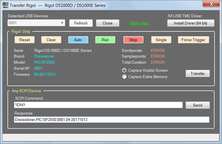
Software zur Datenübertragung eines Rigol Oszilloskops
Auto Run Stop Single Force Trigger Serie: Rigol DS1000D / DS1000E Series Brand: Dreisiebner Model: PIC18F2550 Serial №: 0001 Firmware: 04-20171013 Samlperate: ERROR Samplepoints: ERROR Total Duration: ERROR Capture Visible Screen Capture Entire Memory Transfer Any SCPI Device SCPI Command: *IDN? Send Response: Dreisiebner,PIC18F2550,0001,04-20171013
in „Neue Open Source Software macht aus deinem Oszilloskop einen Logik Analysator“ · PC Hard- und Software · · Screenshots
-
Datei
main.cpp
unsigned char buf[0x400000]; typedef struct { char *name; int devid2; int devid1; } ID; ID pics[] = { {"PIC18F2221", 0x21, 3}, {"PIC18F2321", 0x21, 1}, {"PIC18F2410", 0x11, 3}, {"PIC18F2420", 0x11, 2}, {"PIC18F2450", 0x24, 1}, {"PIC18F2455", 0x12, 3}, {"PIC18F2480", 0x1A, 7}, {"PIC18F2510", 0x11, 1}, {"PIC18F2515", 0x0C, 7}, {"PIC18F2520", 0x11, 0}, {"PIC18F2525", 0x0C, 6}, {"PIC18F2550", 0x12, 2}, {"PIC18F2580", 0x1A, 6}, {"PIC18F2585", 0x0E, 7}, {"PIC18F2610", 0x0C, 5}, {"PIC18F2620", 0x0C, 4}, {"PIC18F2680", 0x0E, 6}, {"PIC18F4221
in „PIC 18Fxxxx programmieren mit Velleman-Bausatz K8048“ · Mikrocontroller und Digitale Elektronik ·
-
Datei
verlinkung.txt
- - PIC18F1320 - - PIC18F1330 - - PIC18F13K22 - - PIC18F13K50 - - PIC18F14K22 - - PIC18F14K50 - - PIC18F2220 - - PIC18F2221 - - PIC18F2320 - - PIC18F2321 - - PIC18F2331 - - PIC18F23K20 - - PIC18F23K22 - - PIC18F2410
in „MC PIC - Warum diese Ungleichbehandlung?“ · Mikrocontroller und Digitale Elektronik ·
-
Datei
usart.txt
= ON #pragma config PBADEN = OFF //PORTB RB4..RB0 #include <delays.h> #include <math.h> #include <p18f2550.h> #include <stdio.h> #include <stdlib.h> #include <config_p18f2550.h> #include <defines.h> #include <usart.h> void init_pic(void) { TRISCbits.TRISC0 = 0; LATCbits.LATC0 = 1; //power LED einschalten
in „USART an pic f18f2550“ · Mikrocontroller und Digitale Elektronik ·
-
Datei
beispiel.html
| PCA9535 | PCI_5V_32BIT | PCI_CONUNIV | PIC16F737 | PIC18F2431 | PIC18F2550 | PIC18F4455_DIP40 | PIC18F4550 | PIC18F45J10_DIP40 | PNP | POINTE | POT | PWR_FLAG | P_TST | R | RELAY-V23092 | RESONATEUR | RJ12 | RJ45 | S5038 | SC16IS7X2_SPI_TSSOP28
in „[KiCad] Bibliotheksaufbau - Konzeptideen gesucht“ · Platinen ·
-
Datei
PICkit_3_Programmer_Application_ReadMe.txt
PIC18F2420 PIC18F2423 PIC18F2431 PIC18F2450 PIC18F2455 PIC18F2458 PIC18F2480 PIC18F2510 PIC18F2515 PIC18F2520 PIC18F2523 PIC18F2525 PIC18F2550 PIC18F2553 PIC18F2580 PIC18F2585 PIC18F2610 PIC18F2620 PIC18F2680 PIC18F2682 PIC18F2685 PIC18F4220 PIC18F4221 PIC18F4320 PIC18F4321 PIC18F4331 PIC18F4410 PIC18F4420 PIC18F4423 PIC18F4431 PIC18F4450 PIC18F4455 PIC18F4458 PIC18F4480 PIC18F4510 PIC18F4515 PIC18F4520 PIC18F4523
in „PICkit3 und Windows 11“ · Mikrocontroller und Digitale Elektronik ·
-
PDF
Real_Time_Clock.pdf
couple onto the Timer1/Timer3 oscillator lines. DS39514A-page 14-16 2000 Microchip Technology Inc. PIC18F2455/2550/4455/4550 12.3.3 TIMER1 OSCILLATOR LAYOUT 12.5 Resetting Timer1 Using the CCP CONSIDERATIONS Special Event Trigger The Timer1 oscillator circuit draws very little power If either of the
in „Uhr mit PIC18“ · Mikrocontroller und Digitale Elektronik ·
-
PDF
sbc28pcr2_ir4.pdf
on the 5 pin terminal block connector. This board has been optimized for the following 28 pin DIP PIC chips: • PIC18F242, PIC18F252, PIC18F248, PIC18F258 • PIC18F2320, PIC18F2410, PIC18F2680 (CAN BUS), PIC18F2550 (USB) • PIC16F870, PIC16F873(A), PIC16F876(A) • PIC16C63, PIC16C66, PIC16C73(A), PIC16F73
in „RS 485 2wire in 4wire umwandeln“ · Mikrocontroller und Digitale Elektronik ·
-
Datei
irsnd.h
IRSND_PIN RA2 #endif #else // Do not change lines below until you have a different HW. Example is for 18F2550/18F4550 // setup macro for PWM used PWM module # if IRSND_OCx == IRSND_PIC_CCP2 # define PWMon() TMR2=0,CCP2CON |=0b1100 # define PWMoff() CCP2CON &=(~0b1100) # define IRSND_PIN TRISCbits.TRISC1
in „IR Fernbedienung mit IRSND“ · Mikrocontroller und Digitale Elektronik ·
-
PDF
brenner8p.pdf
k k 80 1 0 R1 R1 Q4 Q6 BC328-25 BC328-25 IC2 k 1 k 40-poliger Testsockel R 1 R 1 Q3 10nF Q5 BC338-25 BC338-25 21 20 C6 R6 C7 R10 22 19 k 3 k 23 18 10nF 9 0 10k 1 0 10k 24 17 R1 R1 25 16 26 15 C9 27 14 220nF 28 13 29 12 0 1 LSP1 30 11 330 R19 D4 1 P D1 Q7 BAT43 2 1 2 J 31 10 BC328-25 R 680µH
in „Brenner8P von Sprut- Programmierspannungs Probleme“ · Analoge Elektronik und Schaltungstechnik ·
-
PDF
datasheet_FLEX003__v1_03.07.2008_.pdf
AV DD ext JP7 GND AV SS ext Figure 1: FLEX Full Base Board JP8 +5V +3.3V JP9 +USB +5V JP10 DSP_MCLR PIC18_MCLR MORS1 (9-36 V power supply) JP11 DSP_PDATA PIC18_PDATA Pin 1 VINA JP12 Pin 2 VINB DSP_PCLK PIC18_PCLK JP13 VDD pull up - Pin 3 EARTH JP15 SOSCI CRYSTAL JP16 SOSCO CRYSTAL LEDs JP17 GND EARTH
in „LED blinken lassen“ · Mikrocontroller und Digitale Elektronik ·
-
Datei
Rumpf_main.c
files //------------------------------------------------------------------------------ #include <p18cxxx.h> // Header file für alle PIC // Hier kann auch #include <p18F2550.h> bzw. <p18f4550.h> stehen. Mit 18cxxx nimmt der Compiler // das File, das zu dem µC passt, der unter Configure eingestellt ist
in „Mikrocontroller reagiert falsch“ · Mikrocontroller und Digitale Elektronik ·
-
Datei
Rumpf_main.c
files //------------------------------------------------------------------------------ #include <p18cxxx.h> // Header file für alle PIC // Hier kann auch #include <p18F2550.h> bzw. <p18f4550.h> stehen. Mit 18cxxx nimmt der Compiler // das File, das zu dem µC passt, der unter Configure eingestellt ist
in „Mikrocontroller reagiert falsch“ · Mikrocontroller und Digitale Elektronik ·
-
Datei
18F4550_bootloader_4mhz.asm
radix DEC LIST P=18F4550 ; change also: Configure->SelectDevice from Mplab ; 20MHzQuartz / 5 * 24 / 4 => 24MHz ; check _CONFIG1 xtal EQU 24000000 ; 'xtal' here is resulted frequency (is no longer quartz frequency) baud
in „Pic18F4550 Bootloader problem“ · Mikrocontroller und Digitale Elektronik ·
-
Datei
mcp4922.c
// 27.07.2011 // // DAC2 // Testing PIC + MCP4922 12-bit DAC via SPI-Bus #include <htc.h> // Don't forget to link spi-functions in peripheral library // Project -> Build Options... -> Project -> register card Linker // -> Tab 'Linker' ->
in „PIC16F1503 Debugging und andere Dinge.“ · Mikrocontroller und Digitale Elektronik ·
-
Datei
osd02.asm
work anymore ; as suspected, now osd0.hex doesnt work either anymore --> electronic problem LIST P=PIC18F2550 #include <P18f2550.INC> loops Equ 0x22 ; Zähler für Warteschleife loops2 Equ 0x23 ; Zähler für Warteschleife count equ 0x24 ; universal counter OSD_L equ 0x25 OSD_H equ 0x26 count2 equ 0x27 count3
-
PDF
brenner8p5_SCH.pdf
+12V +12V IC2 R8 R12 40-poliger Testsockel 100k 100k 21 20 22 19 Q4 Q6 23 18 BC857ASMD BC857ASMD 24 17 R7 R11 25 16 10k 10k 26 15 VPP_28_40 27 14 VPP_8_14_18 28 13 C6 R9 Q3 R6 10k R10 10k Q5 R13 C7 29 12 GND 1nF 10kBC847SMD BC847SMD 10k 1nF 30 11 GND 31 10 32 9 C8 +5V 33 8 100nF
-
PDF
brenner8p5_1_sch.pdf
22 RB2 RA3/AN3/VREF 6 V 1 21 RB1 RA4/T0CKI 7 3 Z 5 2 C10 INT/RB0 RA5/AN4 D B LSP2 R 2 ICSP 100nF R1 1k 18 9 17 DT/RX/RC7 OSC1/CLKIN 10 CK/TX/RC6 OSC2/CLKOUT 11 14 RC0/T1OSO/T1CKI 12 1k 1 0 Q8 D+ 16 VUSB RC1/T1OSI/CCP2 13 RBF799 BD- 15 D- RC2/CCP1 R15 SVBUS 20 MHz 2 UGND VSS D 100k C1 PIC18F2550SP 8 1 e L R29 220nF Q1 g C14 C11 C2 C3 100nF 100nF GND R18 LED1 C8 22p 22p grün 100nF LSP3 100nF 6 5 10k R 0 R 0 Der Jumper JP1 dient als Backup zurAktivierung des Bootloaders. Zur Verwendung anderer Quarze/Resonatoren
-
Datei
PIC18RC522main.c
(__18F2550)||defined(__18F2455)|| \ defined(__18F4553)||defined(__18F4458)|| \ defined(__18F2553)||defined(__18F2458) // Note: Some of the below configuration bits are commented out // to prevent build errors with some of the above listed devices. // For example, on the PIC18F4458 CP3, WRT3, and EBTR3 don't exist. #pragma config PLLDIV = 5 // (20 MHz input) #pragma config CPUDIV = OSC1_PLL2 #pragma config USBDIV = 2 // Clock source from 96MHz PLL/2 #pragma config FOSC
in „PIC18F & MFRC522: VersionReg“ · Mikrocontroller und Digitale Elektronik ·
-
PDF
ebus.pdf
V IC3 + + 1 5 µ 12 IC2D J 4D 6 2 C1+ 2 C 1 11 1V 1V µ C3 V+ + 13 1 C1- 6 + 4011N 1 IC2P IC3P 4 V- F 4 GND S G 3 µ C2+ µ C 7V 1 C 15 1 GND + C2- GND V 11 14 1 rood PLC OK2 + 10 T1IN T1OUT 7 groen 3k3 1 6 GND 12 T2IN T2OUT 13 geel/zwart 5 9 R1OUT R1IN 8 R2 R2OUT R2IN J 2 4 MAX232 GND 4N35 5 IC2B V 1
in „EBUS - Adapter mit galvanischer Trennung Wolf Gastherme an Pollin AVR-NET-IO mit LCD 4x20“ · Mikrocontroller und Digitale Elektronik ·
-
Datei
-
PDF
andy_mp3_player_schematics.pdf
GPIO1 SO SI GPIO0 uSD-SOCKET SI SO TEST VCC GND J1 C12 C8 C7 C9 C10 C11 GND R3 0 R VPP 1 VCC Q2 100nF 100nF 100nF 100nF 100nF 100nF GND PGD 24.576Mhz PGC C5 C6 PGM GND GND GND GND GND GND GND GND 33pF 33pF ICSP u 1 0 R6 C 1 u AUDIO_JACK 1 0 VCC 15 R7 C 1 VCC GND IC1 GND 15 R1 AUD D1 1 MCLR/VPP RB7/PGD
in „Bauteile für Nachbau MP3 Player gesucht“ · Mikrocontroller und Digitale Elektronik ·
-
Datei
pk2cmdminus_supported_devices.txt
PIC18/PIC18F 0x00000480 PIC18F248 PIC18/PIC18F 0x00000800 PIC18F252 PIC18/PIC18F 0x00000400 PIC18F258 PIC18/PIC18F 0x00000840 PIC18F442 PIC18/PIC18F 0x000004A0 PIC18F448 PIC18/PIC18F 0x00000820 PIC18F452
in „Programmieren eine PIC18F2585 mir einem HEX-File“ · Mikrocontroller und Digitale Elektronik ·
-
Datei
Demo02.c
********************* * FileName: Demo02.c * Dependencies: See INCLUDES section below * Processor: PIC18 * Compiler: C18 2.30.01+ * Company: Microchip Technology, Inc. * * Software License Agreement * * The software supplied herewith by Microchip Technology Incorporated * (the Company ) for its PICmicro
in „PICs mit USB“ · Mikrocontroller und Digitale Elektronik ·
-
Datei
Rumpf_main.c
files //------------------------------------------------------------------------------ #include <p18cxxx.h> // Header file für alle PIC #include <delays.h> #include <stdlib.h> // Hier kann auch #include <p18F2550.h> bzw. <p18f4550.h> stehen. Mit 18cxxx nimmt der Compiler // das File, das zu dem µC passt
in „Interrupts einbinden“ · Mikrocontroller und Digitale Elektronik ·
-
PDF
kicad_8450_dcm_liste_neu_v3.pdf
64B EEPROM, DIP18 PIC16F83-XX/SO PIC16F83, 512B Flash, 36B SRAM, 64B EEPROM, SOIC18 PIC16F84-XX/P PIC16F84, 1K Flash, 68B SRAM, 64B EEPROM, DIP18 PIC16F84-XX/SO PIC16F84, 1KB Flash, 68B SRAM, 64B EEPROM, SOIC18 PIC16F84A-XX
in „KiCAD Eeschema, Bibliotheksdokumentation *.dcm als PDF-Datei“ · Platinen ·
-
Datei
main2.c
(__18F2550)||defined(__18F2455)|| \ defined(__18F4553)||defined(__18F4458)|| \ defined(__18F2553)||defined(__18F2458) // Note: Some of the below configuration bits are commented out // to prevent build errors with some of the above listed devices. // For example, on the PIC18F4458 CP3, WRT3, and EBTR3 don't exist. #pragma config PLLDIV = 5 // (20 MHz input) #pragma config CPUDIV = OSC1_PLL2 #pragma config USBDIV = 2 // Clock source from 96MHz PLL/2 #pragma config FOSC
in „Ausgabe ADC auf HDD44780“ · Mikrocontroller und Digitale Elektronik ·
-
Datei
ea_dip204-4.h
// file ea-dip204-4.h // IN SERIAL MODE // creator Kees Neele // date 23-02-2014 // tested on PIC18F2550 at 16mHz // MPlabX 1.95 // Hi-Tech pro v9.80 #define u8 unsigned char #define s8 signed char #define u16 unsigned int #define s16 signed int #define u24 unsigned short long #define s24 signed
in „Display DIP204-4“ · Mikrocontroller und Digitale Elektronik ·
-
 Bild
Bild
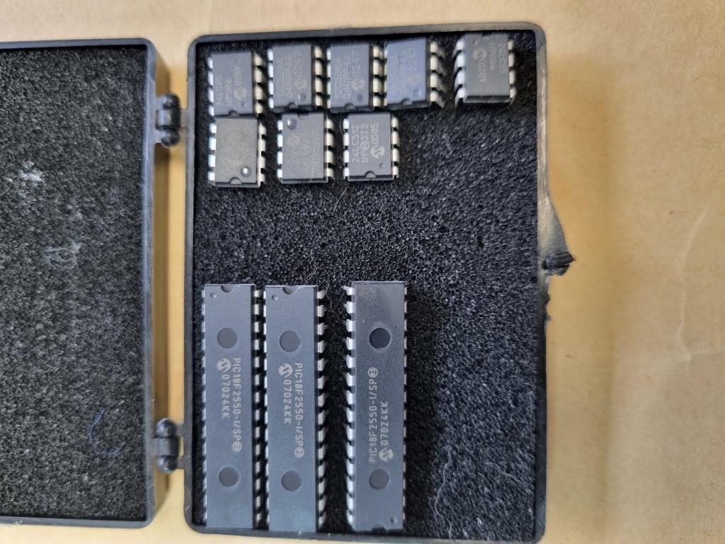
Mikrocontroller in einer Kunststoffbox
PIC18F2550-I/SP 07024KK 24LC512 VF03T2 0505 0709
in „[V] Microchip ICD2 und diverse PIC Mikrocontroller“ · Markt · · Fotos
-
Datei
DeviceList.txt
PIC18F2321(QFNP) PIC18F2410 PIC18F2410(QFN) PIC18F2420 PIC18F2420(QFN) PIC18F2423 PIC18F2423(QFN) PIC18F2450 PIC18F2450(QFN) PIC18F2455 PIC18F2455(QFN) PIC18F2480 PIC18F2480(QFN) PIC18F2510 PIC18F2510(QFN) PIC18F2515 PIC18F2515(QFN) PIC18F2520 PIC18F2520(QFN) PIC18F2523 PIC18F2523(QFN) PIC18F2525 PIC18F2550 PIC18F2580 PIC18F2580(QFN PIC18F2585 PIC18F2610 PIC18F2620 PIC18F2680 PIC18F2680(QFN) PIC18F2682 PIC18F2682
in „[V] Genius G540 EPROM/Flash/uC Programmer (USB)“ · Markt ·
-
Datei
HD44780.INC
HD44780-LCDs ; Succesful tested with ; PIC16F1827, PIC16F628/-A, PIC16F876/-77, PIC16F84 ; Timing: For the LCD ist timing fine up to fosc 32MHz. For exact ; timing in delays use the multiplicator "FOSC_MULT" ; e.g.: movlw .10*FOSC_MULT ; CALL
in „was genau ist eine library“ · Mikrocontroller und Digitale Elektronik ·
-
PDF
device.pdf
MPU/MCU PIC18F2520 NONE No Need WPIC18 V5.39 MICROCHIP MPU/MCU PIC18F2539 NONE No Need WPIC18 V5.39 MICROCHIP MPU/MCU PIC18F2550 NONE No Need WPIC18 V5.39 MICROCHIP MPU/MCU PIC18F258 NONE No Need WPIC18 V5.39 MICROCHIP
-
Datei
bootldra.asm
;NOTE: IF AT ALL POSSIBLE, SET BROWN OUT DETECT TO 'ON' TO AVOID DIRTY POWER ;SUPPLIES KILLING THE PIC MEMORY ;--start email from Herman Aartsen-- ;Dear Shane, ; ;Although I'm still very positive about the PIC16F877 boatloader I have ;recently expierenced a very nasty side effect I think others should
in „PIC16f876A bootloader frage“ · Mikrocontroller und Digitale Elektronik ·
-
Datei
ea_dip204-4.c
// file ea-dip204-4.c // IN SERIAL MODE // creator Kees Neele // date 23-02-2014 // tested on PIC18F2550 at 16mHz // MPlabX 1.95 // Hi-Tech pro v9.80 #include <htc.h> #include "ea_dip204-4.h" bit sflag ; // to test for first data sending [startcode] [=1] or for repeating data transfer [=0] void
in „Display DIP204-4“ · Mikrocontroller und Digitale Elektronik ·