
Hi,
I am designing my own PCB-Board and I am not sure about how to connect
the Reset pin. Is it necessary to connect it? Or could I just  pin it to
the supply voltage, as it is not active in this mode?
Is it advisable to put a button on it, or any other signal?
I am using the microcontroller CC2652R1 from Texas Instruments.

Thanks a lot.
Gast
#6273102
VV V. schrieb:
> Is it advisable to put a button on it, or any other signal?
If your PCB-board is located in an enclosed housing, you don't need a
reset button, as you can't reach it anyway.
Gast
#6273387
True, but housings could also include buttons. So how else would you
connect the pin?
Gast
#6273445
VV schrieb:
> So how else would you connect the pin?

In this way:
1 | |
2 | |
3 | |
4 | |
5 | |
6 | |
7 | |
8 | |
9 | |
10 | |
11 | |
12 | |
13 | |
14 | |
15 | |
16 | |
17 | |
18 | |
19 | |
20 | |
21 | |
22 | |
23 | |
24 | |
25 | |
26 | |
27 | |
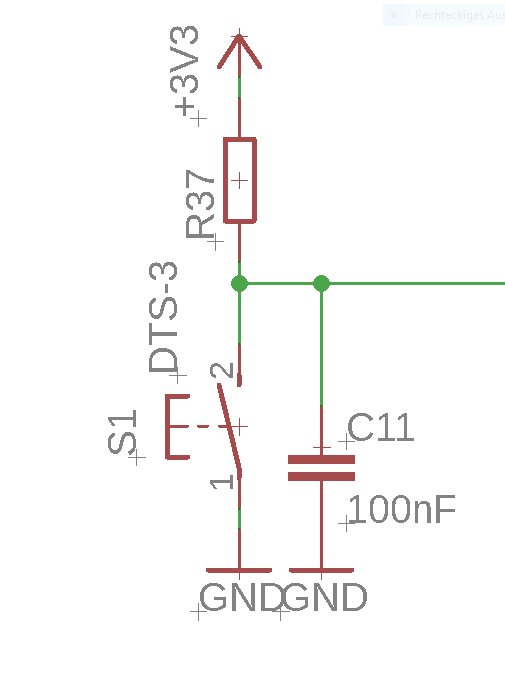
You may decide to use a reset button or not. If not, omit also the 100R.
Reset is also done by a power cycle and it should not be necessary if
your SW is working correctly.
The 100R limits the button current when pressing it and discharging the
capacitor.
D can be any small signal diode e.g. 1N4148. It's preventing a current
from the capacitor into the reset pin, if power is switched off. In most
cases it is not necessary.
Some µCs have a internal pull up so the 10k may also be omitted. I
suggest to use it especially if you like to have a button.

Choose one of them ...
This is a common circuit for the reset pin, the capacitor is for the
Power on Reset. Consult your datasheet for more information, there must
be a chapter about the Pins and there connection.
Angehängte Dateien:
-
 Reset.PNG
(4 KB)
Reset.PNG
(4 KB)
Thank you for your answers.

Frederic S. schrieb:
> Consult your datasheet for more information
That is what I did at the very beginning, but it does not tell me what
to do.

HildeK schrieb:
> Choose one of them ...
I can not clearify what are the two options
1. Button, 100R
2. No button, omit 100R

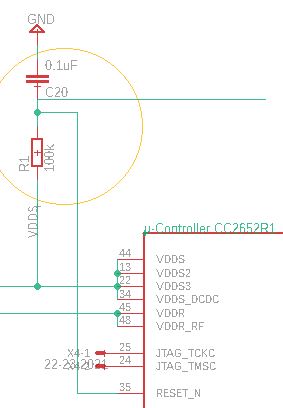
The circuit wich is on the development board looks like in the image,
but then in goes to the debugger. This is what I can't do in my
application.
So here I need a diode connected in parallel?

If I don't need a button, I will not use one.
I am so sorry, but it is not completely clear to me.

Thanks a lot
Angehängte Dateien:
-
 Capture_Reset.JPG
(21 KB)
Capture_Reset.JPG
(21 KB)
Gast
#6280339
Hi,
I just need one more answer for the questions of my last post.
Thanks a lot.
Gast
#6280379
Table 4-1. Signal Descriptions – RGZ Package (Datasheet side 8)

RESET_N 35 I Digital Reset, active low. No internal pullup resistor

Use the circuit recommended by HildeK. If no reset buton necessary, you
can omit it together with 100R resistor.
Gast
#6280438
VV V. schrieb:
> microcontroller CC2652R1 from Texas Instruments.

I'd wonder, if there are neither appnotes nor recommendations in the
datasheet(s).

br mf
Gast
#6280524
Hi,

Ozvald K. schrieb:
> Use the circuit recommended by HildeK.

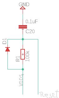
I am no sure about his drawing because of the dashed lines.
Is it meant to be like this? (See image)

minifloat schrieb:
> I'd wonder, if there are neither appnotes nor recommendations in the
> datasheet(s).
I could not find any hint. I have looked through all I have.
Angehängte Dateien:
-
 Restet_2.JPG
(13 KB)
Restet_2.JPG
(13 KB)
Gast
#6280545
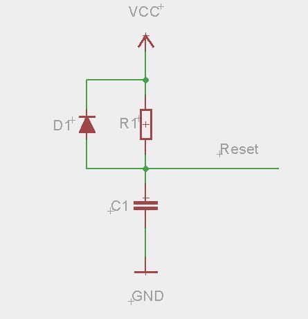
it is meant to be like this image
Angehängte Dateien:
-
 Reset.jpg
(7,3 KB)
Reset.jpg
(7,3 KB)
Gast
#6280569
Next question: How shall I connect the GND pins to my PCB?
VV V. schrieb:
> Is it advisable to put a button on it

If you trust your programming and hardware skills, no button was needed.