Hallo zusammen,

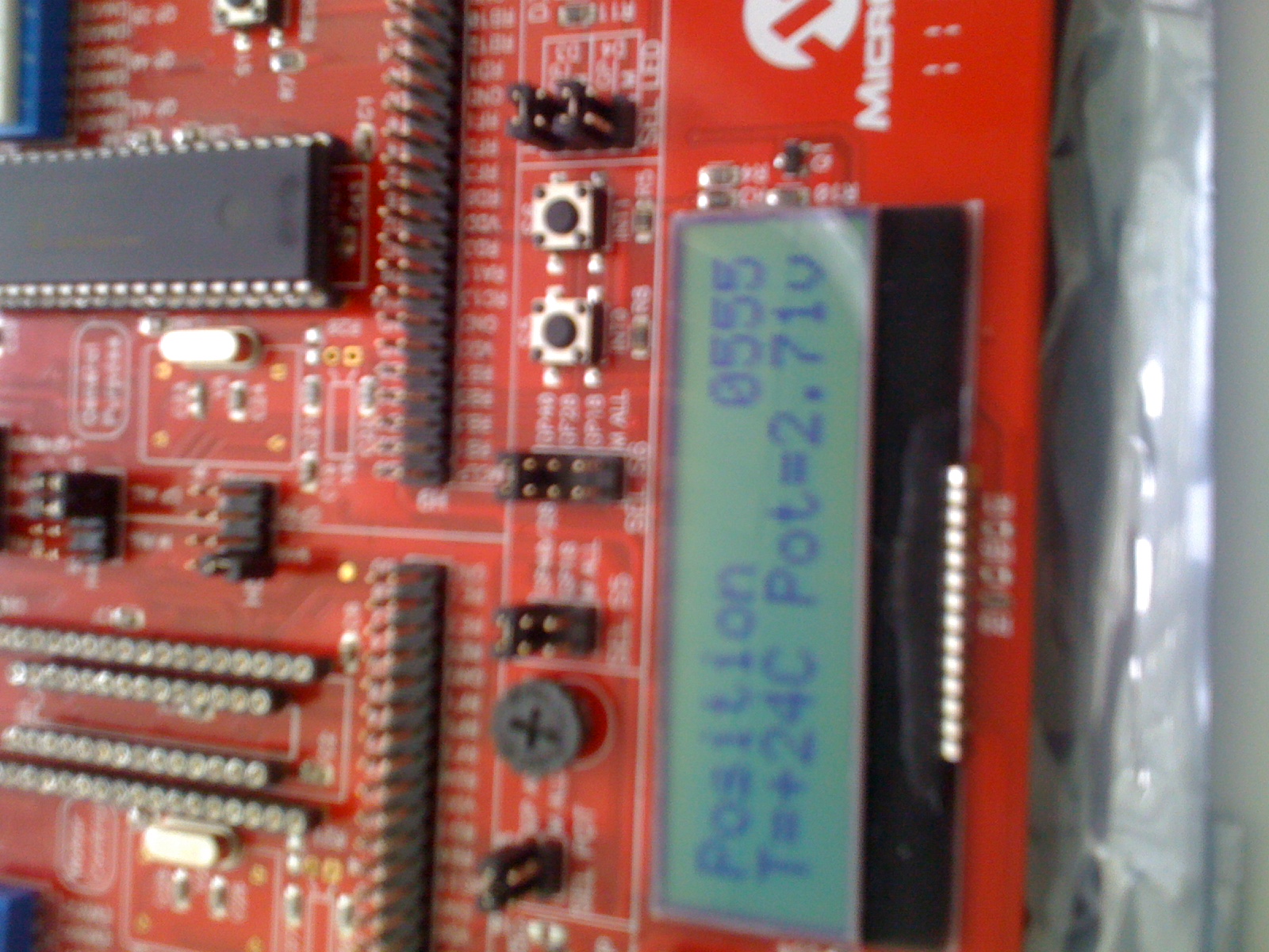
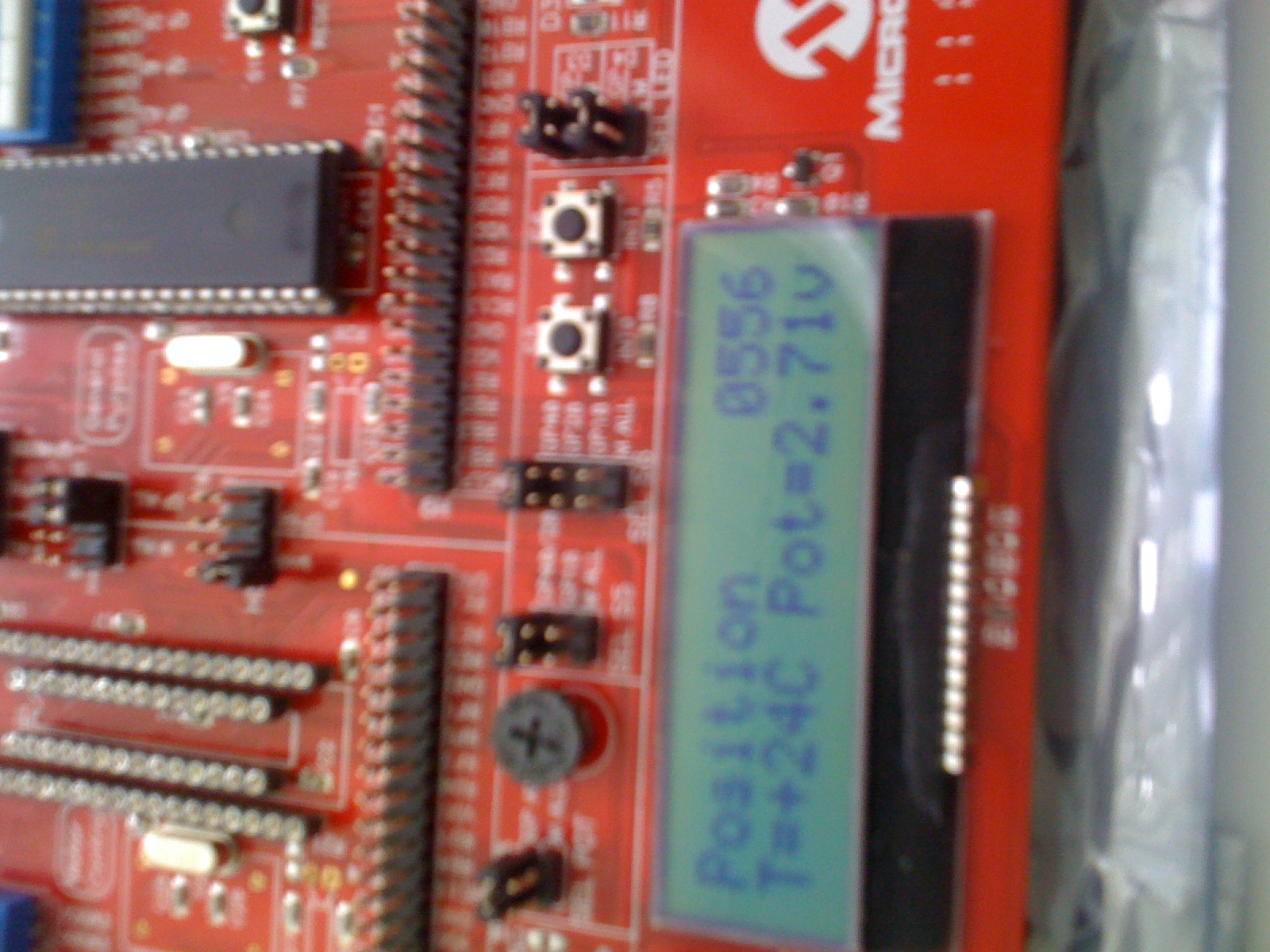
ich versuche seit einem Monat die Spannung die durch den Poti auf meinem
mikrocontroller angezeigt wird zu reglen denn es zappelt an der letzte
Ziffer um +/-1 und verusacht somit somit das Zappeln an der Position der
Abgasegegendruckklappe (das Programm-das eigentlich wenn eine Spannung
an mikrocontroller anliegt, interpretiert es als position und
fährt/stellt die Abgasegegendruckklappe- habe ich nicht selber
geschrieben aber ich muss das erweitern um dieses Zappeln wegzubekommen
d.h die Spannung so filtern dass es nach dem Einstellen durch den Poti
ein fester Wert zeigt und somit als feste position interpretiert
wird)...Manchmal bleit eine gewisse Zeit die Spannung Konstant aber die
Position ändert sich troztdem.
Ich bin kein expert in C (code ist in C geschrieben) auch nicht in
Sachen Mikrocontroller aber ich dachte mir dass ich nur einen Tiefpass
reinprogrammieren soll und das wärs aber es tut dann gar nicht filtern
das Zappelt genauso wie vorher...Ich bin auch jetzt sehr neugierig wie
ich das Problem lösen kann und für Eure Antworte/Fragen sehr dankbar.
PS: Beim Tiefpass() was soll ich da genauer beachten ?

Grüße Robin
Robin schrieb:> ich dachte mir dass ich nur einen Tiefpass reinprogrammieren soll> und das wärs aber es tut dann gar nicht filtern das Zappelt> genauso wie vorher...
Wie sieht denn dein Code aus?
Meinst du nur das Zappeln auf dem letzten Bit?
> denn es zappelt an der letzte Ziffer um +/-1 und verusacht somit> somit das Zappeln an der Position der Abgasegegendruckklappe
Ja, da ist dann wohl zuviel Verstärkung oder P-Anteil in der
Regelstrecke. Denn auf das letzte Bit eines ADCs kann man sich nicht
verlassen. Das steht aber im Datenblatt...
hier ist das Hauptprogramm


//Pre-Processor Directives:
//Provide pre-processor directives to include Device header files and
//any application specific header files. Path locations to the Device
//header files are set up within the MPLAB
Project>>BuildOptions>>Project
//dialog box. The path should point to X:\\MPLAB C30\support\h\, where
//"X:" is the folder where the MPLAB C30 tools are installed.
#include <p30fxxxx.h>   //"p30fxxxx.h" is a generic header file for
dsPIC30F
                        //devices. This file will in turn select the
actual
                        //device header file, based on the device
selected
                        //by the MPLAB workspace/project. Using the
p30fxxxx.h
                        //file makes it easy to migrate a project from
one
                        //dsPIC device to another.
#define _USE_MATH_DEFINES
#include "math.h"
#include "system.h"
     //"system.h" is a header file defined for this
                        //application.

//Macros for Configuration Fuse Registers:
//Invoke macros to set up  device configuration fuse registers.
//The fuses will select the oscillator source, power-up timers,
watch-dog
//timers, BOR characteristics etc. The macros are defined within the
device
//header files. The configuration fuse registers reside in Flash memory.
_FOSC(CSW_FSCM_OFF & XT_PLL8);  //Run this project using an external
crystal
                                //routed via the PLL in 8x multiplier
mode
                                //For the 7.3728 MHz crystal we will
derive a
                                //throughput of 7.3728*10^6*8/4 =
14.7456 MIPS(Fcy)
                                //,~68 nanoseconds instruction cycle
time(Tcy).
_FWDT(WDT_OFF);                 //Turn off the Watch-Dog Timer.
_FBORPOR(MCLR_EN & PWRT_OFF);   //Enable MCLR reset pin and turn off the
                                //power-up timers.
_FGS(CODE_PROT_OFF);            //Disable Code Protection

//Declaration to Link External Functions & Variables:
//Declare functions being used that are defined outside this file, or
//elsewhere in this MPLAB project.
extern SPI_Init(void);
extern UpdateDisplayBuffer(void);
//extern WriteUART_to_RS232(void);
extern WriteSPI_to_LCD(void);
//extern UART_Init(void);
extern ADC_Init(void);
extern INTx_Init(void);
extern Timer2_Init(void);
extern CAN_Init( int pos);
unsigned int position; //Variable für Stellerposition
extern int Potentiometer;  //Variable für ADC-Wert von dem Poti
unsigned int potivorher=0;

unsigned int geglaetteterwert=0;


//Functions and Variables with Global Scope:
//Declare functions in this file that have global scope.
int main (void);

//Code execution automatically reaches the main() function after
//two events have occurred;
//1. A Reset event triggered by hardware or software
//2. The execution of the C Start up library functions, present
//   in the crt0.o file in the libpic30-coff.a library file


unsigned int Tiefpass()

{

float i =0;
float  T=0.00001;
int fg=2000000;
float q,p,gefilterterwert;
q=2*3.14*fg*T;
p=exp(-q);
                  for (i=0;i<=T;i+0.0000005)
                  {
                    gefilterterwert=q*Potentiometer + p*potivorher;
                    potivorher=(int)gefilterterwert;

                  }
return potivorher;
}


int main (void)
{

        ADPCFG = 0xFFFF;        //After reset all port pins multiplexed
                                //with the A/D converter are configred
analog.
                                //We will reconfigure them to be digital
                                //by writing all 1's to the ADPCFG
register.
                                //Note: All dsPIC registers are memory
mapped.
                                //The address of ADPCFG and other
registers
                                //are defined in the device linker
script
                                //in your project.

        //Function Delay5ms() available in file, Delay.s
        Delay5ms(100);          //Provide 500ms delay for the LCD to
start-up.

        //Function SPI_Init() available in file, SPI_for_LCD.c
        SPI_Init();             //Initialize the SPI module to
communicate with
                                //the LCD.

        //Function UART_Init() available in file, UART.c
        //UART_Init();            //Initialize the UART module to
communicate
                                //with the COM port on the Host PC via
an
                                //RS232 cable and the DB9 connector.

        //Function ADC_Init() available in file, A_to_D_Converter.c
        ADC_Init();             //Initialize the A/D converter to
convert
                                //signals from the Temperature Sensor
and the
                                //Potentiometer.

        //Function INTx_IO_Init() available in file, INTx_IO_pins.c
        INTx_IO_Init();         //Initialize the External interrupt pins
and
                                //some I/O pins to accept input from the
                                //switches, S5 and S6 and drive the
LEDs, D3
                                //and D4.

        //Function Timer1_Init() & Timer2_Init() available in file,
Timers.c
        //Timer1_Init();          //Initialize Timer1 to provide
"blinking" time
                                //for the LEDs.
        Timer2_Init();          //Initialize Timer2 and Timer3 as a
32-bit
                                //Timer to be used for updating data
sent to
                                //the LCD(SPI) and COM(UART) interfaces.


        while (1)               //Main Loop of Code Executes forever
        {            //Spannung 0-5 V am RB3, Umschaltung vom Poti auf
Messgalgensignal: Jumper H13


unsigned int Potentiometer = potivorher;
CAN_Init(Potentiometer/4);  //Aufruf der CAN-Funktion zum Senden des
Signals ADC-Wert/4 als Übergabeparameter (ADC_Wert: 0x000-0xFFF)
        //Die Position muss kontinuierlich über CAN geschickt werden
             position=Potentiometer/4;   //Variable Position für die
Ausgabe am Display


                while (IFS0bits.T3IF == 1)      //Wait until 32-bit
Timer
                {                               //interrupt flag bit is
set.
                        IFS0bits.T3IF = 0;      //Clear 32-bit timer
interrupt
                                                //flag bit
                        T2CONbits.TON = 0;      //Stop 32-bit Timer

                        //Function UpdateDisplayBuffer() available
                        //in file, DisplayRoutines.c
                        UpdateDisplayBuffer();  //Write the most recent
                                                //temperature and
potentiometer
                                                //values into display
buffer

                        //Function WriteSPI_to_LCD() in file,
SPI_for_LCD.c
                        WriteSPI_to_LCD();      //Update the LCD via SPI

                        T2CONbits.TON = 1;      //Start 32-bit Timer
again
                }
       }
        return 0;               //Code never reaches here!
}
Hi!

Ein Tiefpass bringt hier wenig. Durch den Tiefpass wird das Zappeln
langsamer, aber weg geht es nicht.

Du kannst eine Hysterese einbauen. Das heißt du merkst dir den Wert des
letzten Samples in einer Variablen und vergleichst ihn mit dem aktuellen
gesampleten Wert. Wenn der Unterschied größer als 1 Bit ist, dann
speicherst du den den aktuellen Wert in der Variable. Wenn der
Unterschied kleiner ist, dann behälst du den Wert in der Variable bei.

Ansonsten hilft die Formartierung mit [ c] und [/c] (ohne Leerzeichen)
ungemein bei der Lesbarkeit des Codes.

Gruß
Stefan
Wooschder schrieb:> Nachnachtrag:>> Wie lange dauert eine Periode des Timers bzw. Wie oft wird der ADC> ausgelesen und das Display aktualisiert?
//Functions:
//ADC_Init() is used to configure A/D to scan and convert 2 input
channels
//per interrupt. The A/D is set up for a total sampling rate of 8KHz
//or 4KHz per channel. The internal counter in the A/D is used to
provide
//Acquisition time delay. The input pins being scanned are AN2 and AN3.
//AN2 and AN3 are connected to the Temperature Sensor and the
Potentiometer
//on the dsPICDEM2 board.
void ADC_Init(void)
{
//ADCON1 Register
//Set up A/D for Automatic Sampling, Auto-Convert
//All other bits to their default state
ADCON1bits.SSRC = 7;
ADCON1bits.ASAM = 1;
//ADCON2 Register
//Set up A/D for interrupting after 2 samples get filled in the
buffer
//Also, enable Channel scanning
//All other bits to their default state
ADCON2bits.SMPI = 1;
ADCON2bits.CSCNA = 1;
//ADCON3 Register
//Set up Acquisition time (Tacq) for 31 Tad periods
//where, Tad = A/D conversion clock time.
//Set up Tad period to be 20.5 Tcy (Tcy = instruction cycle
time)
//Given that each conversion takes 14*Tad (=Tconv) periods,
//Total Sample Time = Acquisition Time + Conversion Time
// = (31 + 14)*Tad = 45*Tad periods
// = 45 * 20.5 * Tcy = 922.5*Tcy periods
//At 7.3728 MIPS, Tcy = 135 ns = Instruction Cycle Time
//So Tsamp = Tacq + Tconv = 45*Tad(in this example)= 125.1
microseconds
//So Fsamp = Sampling Rate ~= 8 KHz
//All other bits to their default state
ADCON3bits.SAMC = 31;
ADCON3bits.ADCS = 40;
//ADCHS Register
//When Channel scanning is enabled (ADCON2bits.CSCNA=1)
//AND Alternate mux sampling is disabled (ADCON2bits.ALTS=0)
//then ADCHS is a "don't care"
ADCHS = 0x0000;
//ADCSSL Register
//Scan channels AN2, AN3 fas part of scanning sequence
ADCSSL = 0x000C;
//ADPCFG Register
//Set up channels AN2, AN3 as analog inputs and leave rest as
digital
//Recall that we configured all A/D pins as digital when code
execution
//entered main() out of reset
ADPCFGbits.PCFG2 = 0;
ADPCFGbits.PCFG3 = 0;
//Clear the A/D interrupt flag bit
IFS0bits.ADIF = 0;
//Set the A/D interrupt enable bit
IEC0bits.ADIE = 1;
//Turn on the A/D converter
//This is typically done after configuring other registers
ADCON1bits.ADON = 1;
}
//_ADCInterrupt() is the A/D interrupt service routine (ISR).
//The routine must have global scope in order to be an ISR.
//The ISR name is chosen from the device linker script.
void __attribute__((_interrupt_)) _ADCInterrupt(void)
{
//Copy the A/D conversion results from ADCBUFn to variables-
//"Potentiometer" and "TempSensor".
//Since ADCON2bits.SMPI = 1, only the first two (i.e. SMPI+1)
ADCBUFn
//locations are used by the module to store conversion results
Potentiometer = ADCBUF0;
TempSensor = ADCBUF1;
//Clear the A/D Interrupt flag bit or else the CPU will
//keep vectoring back to the ISR
IFS0bits.ADIF = 0;
}
meinst du das ?? es gibt auch noch die Funktion delay.s
;Symbol/Literal/Immediate Operand Definitions:
;".equ" directives are similar to "#define" pre-processor directives in
C
.equ NANOSEC125, 2 ;125ns approx = 2*TCY at 14.7 MIPS
.equ MICROSEC, 8*NANOSEC125 ;8*125ns =1us
.equ MILLISEC, 1000*MICROSEC ;1000*1us = 1000*8*125ns = 1ms
;Global Declarations for Functions and variables:
.global _Delay5us
.global _Delay5ms
;Code Sections:
;Code sections are named ".text"
.section .text
_Delay5us:
;Function Prototype for C:
; void Delay5us(int Count)
; Note: "_" prefixed to the function name is not used when calling the
; function from a C file.
; Function Execution Time when Count=1 is 5 microseconds at 14.74 MIPS
;
push w1 ;Store w1 on to stack
mov #MICROSEC, w1 ;w1 = MICROSEC
dec w1, w1 ;w1 = w1 - 1
bra nz, $-2 ;If w1 != 0 then Branch to previous
instruction
dec w0, w0 ;else w0 = w0 - 1
bra nz, $-8 ;If w0 != 0 then Branch back 4
instructions
pop w1 ;else restore w1 from stack
return ;Return to calling routine
_Delay5ms:
;Function Prototype for C:
; void Delay5ms(int Count)
; Note: "_" prefixed to the function name is not used when calling the
; function from a C file.
; Function Execution Time when Count=1 is 5 milliseconds at 14.74 MIPS
push w1 ;Store w1 on to stack
mov #MILLISEC, w1 ;w1 = MILLISEC
dec w1, w1 ;w1 = w1 - 1
bra nz, $-2 ;If w1 != 0 then Branch to previous
instruction
dec w0, w0 ;else w0 = w0 - 1
bra nz, $-8 ;If w0 != 0 then Branch back 4
instructions
pop w1 ;else restore w1 from stack
return ;Return to calling routine
.end ;End of File
Wooschder schrieb:> Nachtrag:Wenn du die Hysterese verwendest, benötigst du keinen Tiefpass.
Danke ich werde dann die hysterese googlen...
aber bei meinem TP
unsigned int Tiefpass()
{
float i =0;
float T=0.00001;
int fg=2000000;
float q,p,gefilterterwert;
q=2*3.14*fg*T;
p=exp(-q);
while (i<=T)
{
gefilterterwert=q*Potentiometer + p*potivorher;
potivorher=(int)gefilterterwert;
i=i+0.0000005;
}
return potivorher;
}
Stimmt überhaupt dieser tp () ?? die filterordnung habe gar nicht
berücksichtig und Werte von T und fg habe ich willkürlich
angenommen...wollte wissen wie ich diese 3 Werte (filterordnung,fg,T)
richtig bestimmen kann und ob man ein TP überhaupt so programmiert...
Vielen Dank !!

 IMG_0288_1_.jpg
(670 KB)
IMG_0288_1_.jpg
(670 KB)
 IMG_0289_1_.jpg
(650 KB)
IMG_0289_1_.jpg
(650 KB)