Hi,
ich möchte eine Funkverbindung mit  nRF24L01 Modulen zwischen zwei esp32
aufbauen.
Dazu habe ich das Modul so verkabelt:

CE         -> GPIO 18
CSN        -> GPIO 05
MISO       -> GPIO 12
MOSI       -> GPIO 13
CLK        -> GPIO 14
IRQ        -> nicht verbunden

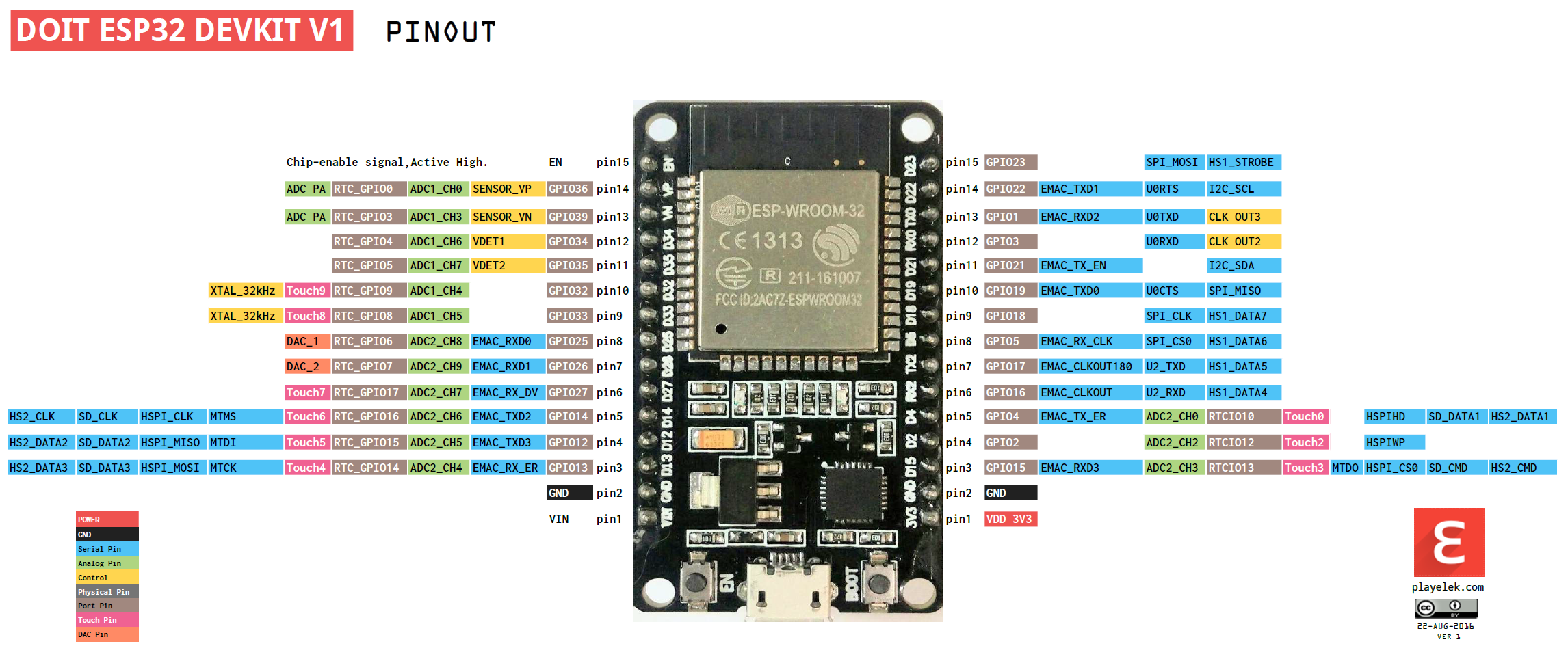
Das Layout vom esp32 ist dieses:
https://raw.githubusercontent.com/playelek/pinout-doit-32devkitv1/master/pinoutDOIT32devkitv1.png

Mein Problem ist, dass keine Verbindung aufgebaut wird.

Das habe ich mit volgendem Code herrausgefunden:
(Das ist die void setup vom "Getting Started" Beispiel, wo ich noch dies
eingefügt habe:
1 | if (radio.begin()) { Serial.println("Alles Super");
|
2 | }
|
3 | else{ Serial.println("Nicht gut");
|
4 | }
|
)
1 | /*
|
2 | * Getting Started example sketch for nRF24L01+ radios
|
3 | * This is a very basic example of how to send data from one node to another
|
4 | * Updated: Dec 2014 by TMRh20
|
5 | */
|
6 |
|
7 | #include <SPI.h>
|
8 | #include "RF24.h"
|
9 |
|
10 | /****************** User Config ***************************/
|
11 | /*** Set this radio as radio number 0 or 1 ***/
|
12 | bool radioNumber = 0;
|
13 |
|
14 | /* Hardware configuration: Set up nRF24L01 radio on SPI bus plus pins 7 & 8 */
|
15 | RF24 radio(5,18); //CE, CSN
|
16 | /**********************************************************/
|
17 |
|
18 | byte addresses[][6] = {"1Node","2Node"};
|
19 |
|
20 | // Used to control whether this node is sending or receiving
|
21 | bool role = 0;
|
22 |
|
23 | void setup() {
|
24 | Serial.begin(115200);
|
25 | Serial.println(F("RF24/examples/GettingStarted"));
|
26 | Serial.println(F("*** PRESS 'T' to begin transmitting to the other node"));
|
27 |
|
28 |
|
29 | if (radio.begin()) { Serial.println("Alles Super");
|
30 | }
|
31 | else{ Serial.println("Nicht gut");
|
32 | }
|
33 |
|
34 | delay(6000);
|
35 | // Set the PA Level low to prevent power supply related issues since this is a
|
36 | // getting_started sketch, and the likelihood of close proximity of the devices. RF24_PA_MAX is default.
|
37 | radio.setPALevel(RF24_PA_LOW);
|
38 |
|
39 | // Open a writing and reading pipe on each radio, with opposite addresses
|
40 | if(radioNumber){
|
41 | radio.openWritingPipe(addresses[1]);
|
42 | radio.openReadingPipe(1,addresses[0]);
|
43 | }else{
|
44 | radio.openWritingPipe(addresses[0]);
|
45 | radio.openReadingPipe(1,addresses[1]);
|
46 | }
|
47 |
|
48 | // Start the radio listening for data
|
49 | radio.startListening();
|
50 | }
|
51 | void loop(){
|
52 | }
|
In der Datei "arduino_pins.h" habe ich volgendes geändert:

Ich habe
1 | static const uint8_t SS = 5;
|
2 | static const uint8_t MOSI = 23;
|
3 | static const uint8_t MISO = 19;
|
4 | static const uint8_t SCK = 18;
|
gegen
1 | static const uint8_t SS = 5;
|
2 | static const uint8_t MOSI = 13;
|
3 | static const uint8_t MISO = 12;
|
4 | static const uint8_t SCK = 14;
|
ausgetauscht.

leider wird im seriellen Monitor der Arduino IDE immer "Nicht gut"
angezeigt.


Ich hoffe, dass mir jemand Weiterhelfen kann.
Viele Güße
Flo