Can someone help me to figure out the purpose of the two different filters?

OP #5344510
I have this long cable which is carrying two differential voltage 
signals (around 300kHz maximum frequency) through a very "noisy" 
environment. I need to acquire this signal through a differential op amp 
(PGA204) and I was thinking about putting a filter at the input of the 
instrumentation OP AMP(to know more about operational amplifier: 
http://www.apogeeweb.net/article/60.html).

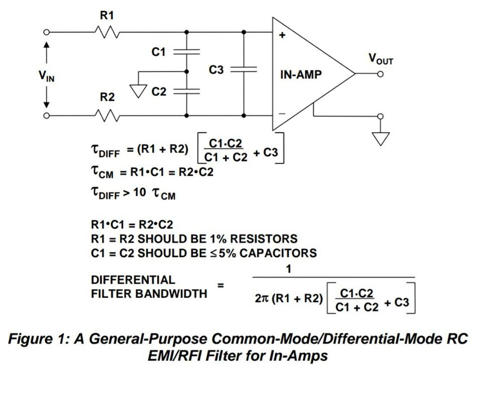
I found this nice filter:
See attachment iGS1m.jpg

But I cannot deeply understand the purpose of the two different filters 
(DM and CM). From what I know, a common-mode noise is a noise present in 
both lines with the same "polarity", while a differential-mode noise is 
a noise which is complementary in respect to the ground in the two 
lines.

What I see in the schematic are three LP filters, two of them (R1 C1 and 
R2 C2) filter the signal in the two lines independently, with respect to 
the ground, while the third one (R1 R2 C3) filters the whole 
differential signal. But aren't we just adding poles to filter the input 
signals? I mean, if I set the cutoff frequency of the two CM filters to 
a certain value, these two filters will just filter the signal within 
the range set. In the same way, the differential filter will just filter 
the input signal within the range set.

    >How exactly do these two filters work together?
    >How can they act on different kinds of noise if they are just LP 
filters?
Angehängte Dateien:
Gast
Linda L. schrieb:
> But I cannot deeply understand the purpose of the two different filters
> (DM and CM). From what I know, a common-mode noise is a noise present in
> both lines with the same "polarity", while a differential-mode noise is
> a noise which is complementary in respect to the ground in the two
> lines.

Correct.
Therefore the C3 does not work on CM signals because there is no voltage 
change above it caused by DM signals or disturbances.
On the other side C1 and C2 work on DM signals because every change of 
the differential input signal will cause a current flow or a voltage 
change above these Cs. But also a CM signal is affected by C1 and C2 
because of the GND connection between them.

You can find that also in the equations of tau_CM and tau_DIFF.

Antwort schreiben

Eine eigene Frage? Dieser Thread ist über 8 Jahre alt. Stell sie in einem eigenen Thread – dort lesen mehr Leute mit, und sie wird öfter und schneller beantwortet.

Neuen Thread starten

Eine Lösung, Ergänzung oder Rückmeldung zu diesem Thread? Dann antworte hier.

Formatierung
  • [c]C-Code[/c]
  • [code]Code in anderen Sprachen, ASCII-Zeichnungen[/code]
  • [math]Formel in LaTeX-Syntax[/math]
  • [[Titel]] – Link zu einem Artikel
  • Verweis auf einen anderen Beitrag: Rechtsklick auf dessen Beitrags-ID (#8078628), „Adresse kopieren“, in den Text einfügen

Mehr zur Formatierung

Längeren Sourcecode als Anhang, nicht in den Text. JPG nur für Fotos und Scans; Zeichnungen und Screenshots als PNG oder GIF. Siehe Bildformate.

Schon registriert? Anmelden

Wird nicht angezeigt. Wir schicken dir einen Link; sobald du damit bestätigst, erscheint dein Beitrag.

Mit dem Abschicken legst du einen kostenlosen Account an und erkennst die Nutzungsbedingungen und die Datenschutzerklärung an.