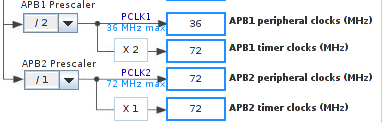
Hallo,

ich möchte bei meinem STM32 USART1 verwenden. Vorerst ohne DMA und nur
Tx. Ich habe ein Beispiel für USART2 gefunden und angepasst ->
funktioniert soweit. Richtiges Zeichen kommt am Computer an.
Jetzt das ganze für USART1 angepasst -> funktioniert nicht.
Es kommt nichts am Computer an.

Ausgewertet wird das ganze von Serial -> USB Adapter und Putty.

Code USART2
1 | void RCC_Enable(void){
|
2 | /* Enable GPIO clock */
|
3 | RCC_AHBPeriphClockCmd(RCC_AHBPeriph_GPIOA, ENABLE);
|
4 | /* Enable USART clock */
|
5 | RCC_APB1PeriphClockCmd(RCC_APB1Periph_USART2, ENABLE);
|
6 | /* Enable DMA2 clock -------------------------------------------------------*/
|
7 | RCC_AHBPeriphClockCmd(RCC_AHBPeriph_DMA1, ENABLE);
|
8 | }
|
9 |
|
10 | void init_all(void) {
|
11 | /*===================================================*/
|
12 | RCC_Enable();
|
13 |
|
14 | GPIO_PinAFConfig(GPIOA, GPIO_PinSource2, GPIO_AF_7);
|
15 | GPIO_PinAFConfig(GPIOA, GPIO_PinSource3, GPIO_AF_7);
|
16 |
|
17 | /* Configure USART Tx as alternate function push-pull */
|
18 | GPIO_InitStructure.GPIO_Pin = GPIO_Pin_2| GPIO_Pin_3;
|
19 | GPIO_InitStructure.GPIO_Mode = GPIO_Mode_AF;
|
20 | GPIO_InitStructure.GPIO_Speed = GPIO_Speed_50MHz;
|
21 | GPIO_InitStructure.GPIO_OType = GPIO_OType_PP;
|
22 | GPIO_InitStructure.GPIO_PuPd = GPIO_PuPd_NOPULL;
|
23 | GPIO_Init(GPIOA, &GPIO_InitStructure);
|
24 |
|
25 | USART2_Config();
|
26 | }
|
27 |
|
28 | void USART2_Config(void){
|
29 | USART_Initialisation.USART_BaudRate = 9600;
|
30 | USART_Initialisation.USART_WordLength = USART_WordLength_8b;
|
31 | USART_Initialisation.USART_StopBits = USART_StopBits_1;
|
32 | USART_Initialisation.USART_Parity = USART_Parity_No;
|
33 | USART_Initialisation.USART_HardwareFlowControl = USART_HardwareFlowControl_None;
|
34 | USART_Initialisation.USART_Mode = USART_Mode_Rx | USART_Mode_Tx;
|
35 | /* USART configuration */
|
36 | USART_Init(USART2, &USART_Initialisation);
|
37 | /* Enable USART */
|
38 | USART_Cmd(USART2, ENABLE);
|
39 | }
|
Code USART1
1 | void RCC_Enable(void){
|
2 | /* Enable GPIO clock */
|
3 | RCC_AHBPeriphClockCmd(RCC_AHBPeriph_GPIOB, ENABLE);
|
4 | /* Enable USART clock */
|
5 | RCC_APB2PeriphClockCmd(RCC_APB2Periph_USART1, ENABLE);
|
6 | /* Enable DMA2 clock -------------------------------------------------------*/
|
7 | RCC_AHBPeriphClockCmd(RCC_AHBPeriph_DMA1, ENABLE);
|
8 | }
|
9 |
|
10 | void init_all(void) {
|
11 | /*===================================================*/
|
12 | RCC_Enable();
|
13 |
|
14 | GPIO_PinAFConfig(GPIOB, GPIO_PinSource6, GPIO_AF_7);
|
15 | GPIO_PinAFConfig(GPIOB, GPIO_PinSource7, GPIO_AF_7);
|
16 |
|
17 | /* Configure USART Tx as alternate function push-pull */
|
18 | GPIO_InitStructure.GPIO_Pin = GPIO_Pin_6| GPIO_Pin_7;
|
19 | GPIO_InitStructure.GPIO_Mode = GPIO_Mode_AF;
|
20 | GPIO_InitStructure.GPIO_Speed = GPIO_Speed_50MHz;
|
21 | GPIO_InitStructure.GPIO_OType = GPIO_OType_PP;
|
22 | GPIO_InitStructure.GPIO_PuPd = GPIO_PuPd_NOPULL;
|
23 | GPIO_Init(GPIOB, &GPIO_InitStructure);
|
24 |
|
25 | USART1_Config();
|
26 | }
|
27 |
|
28 | void USART1_Config(void){
|
29 | USART_Initialisation.USART_BaudRate = 9600;
|
30 | USART_Initialisation.USART_WordLength = USART_WordLength_8b;
|
31 | USART_Initialisation.USART_StopBits = USART_StopBits_1;
|
32 | USART_Initialisation.USART_Parity = USART_Parity_No;
|
33 | USART_Initialisation.USART_HardwareFlowControl = USART_HardwareFlowControl_None;
|
34 | USART_Initialisation.USART_Mode = USART_Mode_Rx | USART_Mode_Tx;
|
35 | /* USART configuration */
|
36 | USART_Init(USART1, &USART_Initialisation);
|
37 | /* Enable USART */
|
38 | USART_Cmd(USART1, ENABLE);
|
39 | }
|
Zeichen wird so gesendet
1 | USART_SendData(USART2, tx_var);
|
bzw.
1 | USART_SendData(USART1, tx_var);
|
Habt ihr eine Idee warum USART1 nicht funktioniert?