-
Datei
BLE_Keyboard5.ino
/* Bluetooth BLE Keyboard - Deutsches Tastaturlayout (QWERTZ) ESP32 wird per USB an den Sender-PC angeschlossen und sendet Tastenanschlaege per BLE an den Ziel-Rechner. Benutzung mit minicom (Linux) als Sender: minicom -D /dev/ttyUSB0 Hardware: ESP32 WROOM Framework: Arduino ESP32 Bibliotheken: https://github.com/HijelHub/HijelHID_BLEKeyboard https://github.com/h2zero/NimBLE-Arduino 2026-08-17 mchris (Claude support), Version für deutsche Tastatur */ #include <HijelHID_BLEKeyboard.h> HijelHID_BLEKeyboard keyboard("ESP32 Tastatur", "Deutsch", 100); // Sendet einen Unicode-Codepoint so, dass am Host
in „Remote Tastatur“ · Projekte & Code ·
-
Datei
BLE_Keyboard2.ino
/* Bluetooth BLE Keyboard Use an ESP32 as Bluetooth keyboard. The ESP is connected to the sender PC via USB and sends keystrokes by BLE. Minicom as Key sender: minicom -D /dev/ttyUSB0 Hardware: ESP32 WROOM Framework Arduino ESP32 Libraries needed: https://github.com/HijelHub/HijelHID_BLEKeyboard https://github.com/h2zero/NimBLE-Arduino Inspired from https://class.academany.org/futures/cybersecurity/2026/labs/isafjordur/students/hanndoddi/cyber-road/lapboard/ 2026-08-13 initial version, mchris */ #include <HijelHID_BLEKeyboard.h> HijelHID_BLEKeyboard keyboard; void setup() { Serial.begin(115200);
in „Remote Tastatur“ · Projekte & Code ·
-
Thread
Arduino: serielles Ansprechen eines HD44780 Displays über SoftSerial
Im Anhang gibt es ein Archiv, in dem zum einen der Empfängersketch enthalten ist: stxlcdrecv_uart.ino sowie eine weitere gepackte Zip-Datei, die mittels der Libraryverwaltung on Arduino installiert werden kann. Jetzt bin ich am überlegen gewesen, ob ich jede einzelne Sourcedatei hier noch einmal
Projekte & Code ·Ralph S. · ·1 Antworten
-
Datei
stxuartlcd_demo_all.ino
/* -------------------------------------------------------- stxuartlcd_demo_all.ino Demosketch:Ansteuerung eines HD44780 kompatiblen Displays, welches über "stxlcdrecv_uart" angesteuert wird. Verbindung wird ueber SoftwareSerial mit einer Baudrate von 4800 bd hergestellt 30.05.2026
in „Arduino: serielles Ansprechen eines HD44780 Displays über SoftSerial“ · Projekte & Code ·
-
Datei
stxuartlcd_demo1.ino
/* -------------------------------------------------------- stxuartlcd_demo1.ino Demosketch:Ansteuerung eines HD44780 kompatiblen Displays, welches über "stxlcdrecv_uart" angesteuert wird. Zeigt Verwendung der originalen Arduino-Methoden print / println in Verbindung mit Einlesen
in „Arduino: serielles Ansprechen eines HD44780 Displays über SoftSerial“ · Projekte & Code ·
-
Datei
stxuartlcd_demo0.ino
/* -------------------------------------------------------- stxuartlcd_demo0.ino Demosketch:Ansteuerung eines HD44780 kompatiblen Displays, welches über "stxlcdrecv_uart" angesteuert wird. Zeigt Verwendung der originalen Arduino-Methoden print / println in Verbindung mit Einlesen
in „Arduino: serielles Ansprechen eines HD44780 Displays über SoftSerial“ · Projekte & Code ·
-
PDF
displayinterface_arduino.pdf
ausschließlich dem Zweck dient, dieses Interface bereitzustellen. Die Firmwaredatei ist: stxlcdrecv_uart.ino Innerhalb dieser Datei ist eine Anpassung bezüglich der Anschlussbelegung Mikrocontroller und Display zu machen, damit ein fehlerfreier Betrieb möglich ist. // Anschluesse Textdisplay an Arduino static
in „Arduino: serielles Ansprechen eines HD44780 Displays über SoftSerial“ · Projekte & Code ·
-
Datei
MSP3400_ATMEGA32_ADC_2.ino
#include <IRremote.hpp> #include <Wire.h> // --------------------------------------------------------- // PIN‑MAPPING (ELECTRONICFOX 2026(c), PORT‑BASIERT, ATmega32) // --------------------------------------------------------- // IR‑Empfänger: PB2 // Tasten: PB0, PD3, PD4, PD5 // Display‑Bus: CLK=PD2, DLEN=PB6, DATA=PB1 // Test/Power: TEST=PB5 // SC‑Out: SC=PD6 // Statusports: LED1=PC3=SUCHLAUF, LED2=PB4=MEMORY // PWM-DAC: PB3 (Timer0), PD7 (Timer2) // ADC: ADC2 (PA2), ADC3 (PA3) // --------------------------------------------------------- #define IR_RECEIVE_PIN PIN_PB2 // PB2 IR-Eingang // Display
in „AUDIOCONTROLLER MSP3400C einfach mit ATMEGA32 ansteuern“ · Projekte & Code ·
-
Datei
MSP3400_ATMEGA32_ADC_2.ino
#include <IRremote.hpp> #include <Wire.h> // --------------------------------------------------------- // PIN‑MAPPING (ELECTRONICFOX 2026(c), PORT‑BASIERT, ATmega32) // --------------------------------------------------------- // IR‑Empfänger: PB2 // Tasten: PB0, PD3, PD4, PD5 // Display‑Bus: CLK=PD2, DLEN=PB6, DATA=PB1 // Test/Power: TEST=PB5 // SC‑Out: SC=PD6 // Statusports: LED1=PC3=SUCHLAUF, LED2=PB4=MEMORY // PWM-DAC: PB3 (Timer0), PD7 (Timer2) // ADC: ADC2 (PA2), ADC3 (PA3) // --------------------------------------------------------- #define IR_RECEIVE_PIN PIN_PB2 // PB2 IR-Eingang // Display
in „Zeigt her eure Kunstwerke (ab 2023)“ · Projekte & Code ·
-
Datei
avr_adafruit_logodraw.ino
#include <Adafruit_GFX.h> #include <Adafruit_ST7735.h> #include <SPI.h> #define TFT_CS 10 // PB2 #define TFT_RST 6 // PD6 #define TFT_DC 7 // PD7 Adafruit_ST7735 tft = Adafruit_ST7735(TFT_CS, TFT_DC, TFT_RST); // RGB565 Farbpallete der "EGA"-Farben uint16_t egapalette [] = { 0x0000, 0x0015, 0x0540, 0x0555, 0xa800, 0xa815, 0xaaa0, 0xad55, 0x52aa, 0x52bf, 0x57ea, 0x57ff, 0xfaaa, 0xfabf, 0xffea, 0xffff }; /* ---------------------------------------------------------- rgbfromvalue Setzt einen 16-Bitfarbwert aus 3 einzelnen Farbwerten fuer (r)ot, (g)ruen und (b)lau zusammen. r,g,b : 8-Bit Farbwerte
in „Turtlegrafik: Interpreter, Creator & Designer“ · Projekte & Code ·
-
Datei
Doppelpuls.ino
/* * Doppelpulsgenerator für Anzeige in CNC Maschine * PB0 und PB2 als Open Drain Signale für Pulsgeber * * ATtiny25/45/85 @ 8MHz * */ #include "util/delay.h" #include "avr/sleep.h" void setup() { GIMSK = (1<<INT0) | (1<<PCIE); MCUCR = (1<<ISC01); // INT0 bei fallender Flanke PCMSK = (1<<PCINT0); DDRB = 0; PORTB = 0b11010; } void loop() { set_sleep_mode(SLEEP_MODE_IDLE); sleep_mode(); } ISR(PCINT0_vect) { _delay_us(20); DDRB = (1<<PB0); // ouptput, LOW _delay_us(20); DDRB = 0; // input _delay_us(50); GIFR = (1<<PCIF); } ISR(INT0_vect) { _delay_us(20); DDRB = (1<<PB2); // ouptput, LOW _delay_us(20
in „Impulsverdoppler für alte Heidenhain Anzeige“ · Projekte & Code ·
-
Datei
Doppelpuls.ino
/* * Doppelpulsgenerator für Anzeige in CNC Maschine * PB0 und PB1 als Open Drain Signale für Pulsgeber * * ATtiny25/45/85 @ 8MHz * */ #include "util/delay.h" #include "avr/sleep.h" void setup() { GIMSK = (1<<INT0) | (1<<PCIE); MCUCR = (1<<ISC01); // INT0 bei fallender Flanke PCMSK = (1<<PCINT0); PORTB = 0b11100; } void loop() { set_sleep_mode(SLEEP_MODE_IDLE); sleep_mode(); } ISR(PCINT0_vect) { _delay_us(20); DDRB = (1<<PB0); // ouptput, LOW _delay_us(20); DDRB = 0; // input _delay_us(50); GIFR = (1<<PCIF); } ISR(INT0_vect) { _delay_us(20); DDRB = (1<<PB1); // ouptput, LOW _delay_us(20); DDRB =
in „Impulsverdoppler für alte Heidenhain Anzeige“ · Projekte & Code ·
-
Datei
Doppelpuls.ino
/* * Doppelpulsgenerator für Anzeige in CNC Maschine * PB0 ud PB1 als Open Drain Signale für Pulsgeber */ #include "util/delay.h" #include "avr/sleep.h" void setup() { GIMSK = (1<<INT0) | (1<<PCIE); PCMSK = (1<<PCINT0); PORTB = 0b11110; } void loop() { set_sleep_mode(SLEEP_MODE_IDLE); sleep_mode(); } ISR(PCINT0_vect) { _delay_us(20); DDRB = (1<<PB0); // ouptput, LOW _delay_us(20); DDRB = 0; // input _delay_us(50); GIFR = (1<<PCIF); } ISR(INT0_vect) { _delay_us(20); DDRB = (1<<PB1); // ouptput, LOW _delay_us(20); DDRB = 0; // input _delay_us(50); GIFR = (1<<INTF0); }
in „Impulsverdoppler für alte Heidenhain Anzeige“ · Projekte & Code ·
-
Datei
Reset_Toner_Chip_SP150.ino
with Arduino Uno R3 // Sources: // http://www.mikrocontroller.net/topic/369267 // AND // FILE: Reset.ino // AUTHOR: Ludovic Guégan adjusted for SP150 Viktor D. // VERSION: 0.2 // PURPOSE: Reset chip for Ricoh SP150 toner // DATE: 2026-03-016 // // Released to the public domain //Wirings: #include <Wire.h
in „Hack: Ricoh Aficio SP100e Toner Chip“ · Projekte & Code ·
-
Datei
Digitalanzeige.ino
const byte input_pin = 3; // Pin 2 am ATtiny45 (PB3) const byte output_pin = 4; // Pin 7 am ATtiny45 (PB2) bool last_state = HIGH; unsigned long last_trigger_time = 0; const unsigned long min_interval = 50; // Mikrosekunden // Für Impulssteuerung bool pulse_pending = false; bool pulse_active = false; unsigned long pulse_start_delay_time = 0; unsigned long pulse_start_time = 0; const unsigned long pulse_delay = 20; // Mikrosekunden Verzögerung vor Impuls const unsigned long pulse_duration = 20; // Mikrosekunden Impulsdauer void setup() { pinMode(input_pin, INPUT); pinMode(output_pin, OUTPUT); digitalWrite
in „Impulsverdoppler für alte Heidenhain Anzeige“ · Projekte & Code ·
-
Datei
FunktionierendeSpamBluetooth.ino
#include "NDP.h" #include <ArduinoBLE.h> // BLE Service & Characteristic UUIDs BLEService matchService("12345678-1234-1234-1234-1234567890AB"); BLEByteCharacteristic matchChar("87654321-4321-4321-4321-BA0987654321", BLERead | BLENotify); volatile uint8_t matchID = 0; volatile bool matchPending = false; volatile int lastLabelIndex = -1; // letztes gesendetes Label merken // Alle Labels in Array definieren const char* labels[] = { "Combat", "Helmet", "Iron Man", "Repulsor", "Shutdown", "Startup", "Stones", "noise", "unknown" }; // Callback bei Match void sendMatch(int labelIndex) { // Nur neues Label
-
Bild
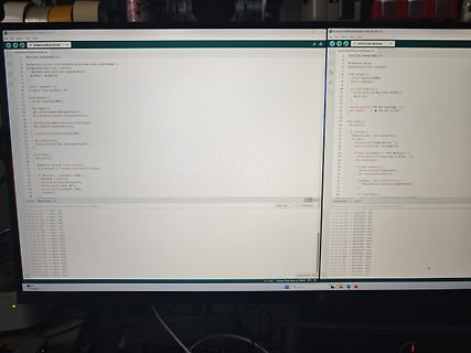
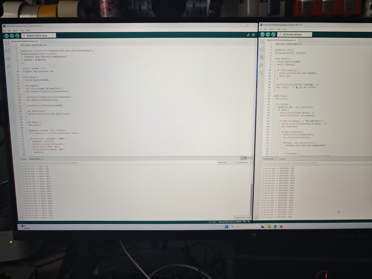
Foto eines Computerbildschirms mit Arduino-Code und Seriellem Monitor
Arduino Nilda Voice BluetoothBLEModule.ino #include <ArduinoBLE.h> void setup() { Serial.begin(115200); if (!BLE.begin()) { while (1); } BLE.setLocalName("BLE Test"); BLE.setAdvertisedService(service); BLE.addService(service); BLE.advertise(
in „Nicla Voice am ESP32“ · Projekte & Code · · Fotos
-
Datei
BluetoothESPKAnnEmpfangen.ino
#include <ArduinoBLE.h> BLEDevice nicla; BLECharacteristic testChar; void setup() { Serial.begin(115200); while (!Serial); if (!BLE.begin()) { Serial.println("BLE init failed"); while (1); } Serial.println("ESP BLE scanning..."); BLE.scan(); // 🔥 DAS HAT GEFEHLT } void loop() { BLE.poll(); if (!nicla) { BLEDevice dev = BLE.available(); if (dev) { Serial.print("Found device: "); Serial.println(dev.localName()); if (dev.localName() == "NiclaBLETest") { Serial.println("Connecting to Nicla..."); BLE.stopScan(); if (dev.connect()) { Serial.println("Connected"); dev.discoverAttributes(); testChar = dev.characteristic
-
Datei
BluetoothNiclaKannSenden.ino
#include <ArduinoBLE.h> BLEService testService("12345678-1234-1234-1234-1234567890ab"); BLEByteCharacteristic testChar( "87654321-4321-4321-4321-ba0987654321", BLERead | BLENotify ); uint8_t counter = 1; unsigned long lastSend = 0; void setup() { Serial.begin(115200); BLE.begin(); BLE.setLocalName("NiclaBLETest"); BLE.setAdvertisedService(testService); testService.addCharacteristic(testChar); BLE.addService(testService); testChar.writeValue((byte)0x00); BLE.advertise(); Serial.println("BLE Test Advertised"); } void loop() { BLE.poll(); BLEDevice central = BLE.central(); if (!central || !central.connected
-
Datei
BluetoothESP.ino
#include <BLEDevice.h> #include <BLEUtils.h> #include <BLEScan.h> #include <BLEAdvertisedDevice.h> #define LED_PIN 2 // LED blinkt bei Match BLEScan* pBLEScan; BLEAdvertisedDevice* myDevice = nullptr; bool deviceFound = false; // UUIDs müssen mit Nicla Peripheral übereinstimmen const char* SERVICE_UUID = "12345678-1234-1234-1234-1234567890AB"; const char* CHAR_UUID = "87654321-4321-4321-4321-BA0987654321"; class MyAdvertisedDeviceCallbacks: public BLEAdvertisedDeviceCallbacks { void onResult(BLEAdvertisedDevice advertisedDevice) { if (advertisedDevice.getName() == "NiclaVoiceBLE") { myDevice = new
-
Datei
BluetoothNicla.ino
#include "NDP.h" #include <ArduinoBLE.h> // BLE Service & Characteristic UUIDs BLEService matchService("12345678-1234-1234-1234-1234567890AB"); BLEByteCharacteristic matchChar("87654321-4321-4321-4321-BA0987654321", BLERead | BLENotify); volatile uint8_t matchID = 0; // ID für Match // Callback bei Match void sendMatch(char* label) { // LED blau bei Match nicla::leds.begin(); nicla::leds.setColor(blue); delay(200); nicla::leds.setColor(off); nicla::leds.end(); // Byte setzen if (strcmp(label, "NN0:Helmet") == 0) matchID = 0x01; else if (strcmp(label, "NN0:Iron Man") == 0) matchID = 0x02; else
-
Datei
I2CESP.ino
#include <Wire.h> #define NICLA_MASTER_ADDR 0x42 #define LED_PIN 2 #define I2C_SDA 19 #define I2C_SCL 16 volatile uint8_t lastMatch = 0; void receiveEvent(int howMany) { while (Wire.available()) { lastMatch = Wire.read(); if (lastMatch != 0) { digitalWrite(LED_PIN, HIGH); delay(150); digitalWrite(LED_PIN, LOW); delay(150); } } } void setup() { pinMode(LED_PIN, OUTPUT); digitalWrite(LED_PIN, LOW); Wire.begin(NICLA_MASTER_ADDR, I2C_SDA, I2C_SCL); Wire.onReceive(receiveEvent); } void loop() { // passiv warten }
-
Datei
I2CVersuch.ino
#include "NDP.h" #include <Wire.h> #define ESP_SLAVE_ADDR 0x42 volatile uint8_t matchToSend = 0; void sendit(char* label) { // LED blau bei Match nicla::leds.begin(); nicla::leds.setColor(blue); delay(200); nicla::leds.setColor(off); nicla::leds.end(); if (strcmp(label, "NN0:Helmet") == 0) matchToSend = 0x01; else if (strcmp(label, "NN0:Iron Man") == 0) matchToSend = 0x02; else if (strcmp(label, "NN0:Shutdown") == 0) matchToSend = 0x03; else if (strcmp(label, "NN0:Startup") == 0) matchToSend = 0x04; else if (strcmp(label, "NN0:Repulsor") == 0) matchToSend = 0x05; else if (strcmp(label, "NN0:Stones
-
Datei
NiclaVoice.ino
#include "NDP.h" #include <Wire.h> // UART TX-Pin auf LP101EXT/P0.20 #define NICLA_TX Serial1 void sendit(char* label) { // LED blau bei Match nicla::leds.begin(); nicla::leds.setColor(blue); delay(200); nicla::leds.setColor(off); nicla::leds.end(); // Senden der Bytes an ESP32 if (strcmp(label, "NN0:Helmet") == 0) { NICLA_TX.write(0x01); } else if (strcmp(label, "NN0:Iron Man") == 0) { NICLA_TX.write(0x02); } else if (strcmp(label, "NN0:Shutdown") == 0) { NICLA_TX.write(0x03); } else if (strcmp(label, "NN0:Startup") == 0) { NICLA_TX.write(0x04); } else if (strcmp(label, "NN0:Repulsor") == 0) {
-
Datei
ESP32_BMP280_espNowDeepSleep4.ino
/* ESP32 BMP280 sender with DEEP SLEEP (3 seconds) BMP280 and BME280 sensor can be used: Enable it with the #define in the code You have also to adapt the receiver MAC in the code. external libraries: Temperature and Pressure Sensor https://github.com/mahfuz195/BMP280-arduino-library or Temperature, Pressure and Humidty Sensor https://github.com/hasenradball/Bosch_BME280_Arduino.git 2026-01-30 mchris V3: first usable version 2026-01-31 mchris V4: Battery measurement added */ #include "BMP280.h" #include "Wire.h" #include <esp_now.h> #include <WiFi.h> #include "esp_adc_cal.h" //#define USE_BMP280
-
Datei
ESP32_BMP280_espNowDeepSleep3.ino
/* ESP32 BMP280 sender with DEEP SLEEP (3 seconds) BMP280 and BME280 sensor can be used: Enable it with the #define in the code You have also to adapt the receiver MAC in the code. external libraries: Temperature and Pressure Sensor https://github.com/mahfuz195/BMP280-arduino-library or Temperature, Pressure and Humidty Sensor https://github.com/hasenradball/Bosch_BME280_Arduino.git 2026-01-30 mchris */ #include "BMP280.h" #include "Wire.h" #include <esp_now.h> #include <WiFi.h> //#define USE_BMP280 #define USE_BME280 #ifdef USE_BME280 #include <Bosch_BME280_Arduino.h> // global instance BME::
-
Thread
Projektvorstellung: Gasheizung überwachen
kostenlosen Grafana-Account. Ich kenne mich mit PHP nicht aus, aber bei der Durchsicht deines ESP_gas.ino kam mir dadurch einiges bekannt vor :) LG, Sebastian
Projekte & Code ·Sebastian A. · ·51 Antworten
-
Datei
blink_int_v003.ino
/* ----------------------------------------------------- blink_int_v003.ino Blinkprogramm fuer CH32V003 mittels Interrupt Timer2 ----------------------------------------------------- */ #define LED PD5 /* -------------------------------------------------------- TIM2_IRQHandler
in „CH23V003 und Arduino: Verwendung Timer2 Interrupt“ · Projekte & Code ·
-
Datei
FC10_Split_text.ino
/* LICENCE see end of file! */ /* Environemental note The program is created for Arduino/ESP8266 and is tested on WIN10 only! */ /* --->>> READ THIS: <<<--- Developer, don't forget to update the version number here! */ // File main control ---------------------------------------------------------- #pragma once // Use this file only once to avoid redefinition problems class SplitText { /** * @class SplitText * @brief Utility class for identifying start and end indices of "words" * within a text using protected and non-protected delimiters. * * This class is a helper class to OledPrint and processes
in „Flexible SplitText() Klasse (Anfänger)“ · Projekte & Code ·
-
Datei
fermenting-control.ino
/* LICENCE see end of file! */ /* Environemental note The program is created for Arduino/ESP8266 and is tested on WIN10 only! */ /* --->>> READ THIS: <<<--- Developer, don't forget to update the version number here! */ // Values visible in THIS file only! // namespace SelfValues { // static constexpr char FILE_AND_VERSION[] = "00.0025"; // } #ifndef DUMMY // Macro statements ============================================= #ifndef DUMMY // 3rd party includes ------------------------------------------- // 3rd party files #include <Arduino.h> #include <Streaming.h> // For convenient printouts to Serial
in „Flexible SplitText() Klasse (Anfänger)“ · Projekte & Code ·
-
Datei
taschenrechner.ino
#include <MCUFRIEND_kbv.h> #include <Adafruit_GFX.h> #include <TouchScreen.h> #include <avr/wdt.h> #define MINPRESSURE 200 #define MAXPRESSURE 1000 const int XP = 8, XM = A2, YP = A3, YM = 9; const int TS_LEFT = 125, TS_RT = 920, TS_TOP = 948, TS_BOT = 97; TouchScreen ts = TouchScreen(XP, YP, XM, YM, 300); MCUFRIEND_kbv tft; const char* button_labels[5][5] = { {"7", "8", "9", "/", "C"}, {"4", "5", "6", "*", "<-"}, {"1", "2", "3", "-", "("}, {"0", ".", "=", "+", ")"}, {"sqrt", "x^2", "1/x", "%", "+/-"} }; #define ROWS 5 #define COLS 5 int pixel_x, pixel_y; #define STACK_MAX 12 float numStack[STACK_MAX
in „Taschenrechner mit Touchscrenn und Serieller Eingabe auf Arduino Uno gequetscht“ · Projekte & Code ·
-
Datei
10.split_text.058.ino
/* LICENCE see end of file! */ /* Environemental note The program is created for Arduino/ESP8266 and is tested on WIN10 only! */ /* --->>> READ THIS: <<<--- Developer, don't forget to update the version number in the private section of the class! */ #ifndef DUMMY // Mandatory Preprocessor Items ================================= // Meta items --------------------------------------------------------------- #ifndef _10_SPLIT_TEXT_IS_STANDALONE #define _10_SPLIT_TEXT_IS_STANDALONE true // If running as a standalone #endif // _10_SPLIT_TEXT_IS_STANDALONE // REQUIRED IN GLOBAL SPACE ================
in „Flexible SplitText() Klasse (Anfänger)“ · Projekte & Code ·
-
Bild
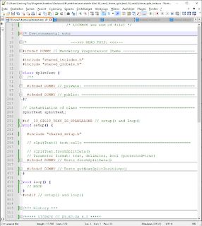
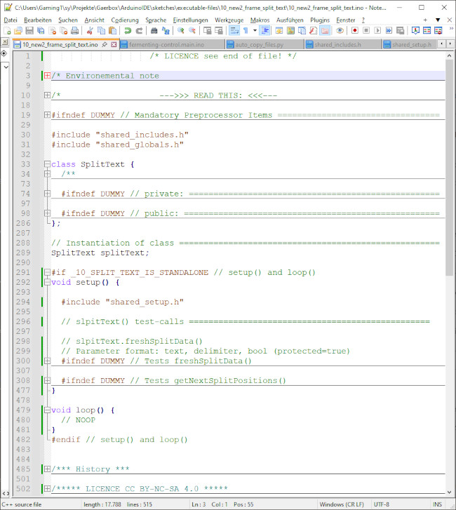
C++ Quellcode in einem Texteditor
Projects\Gearbox\Arduino\DS\sketch\escribable_files\10_new2_frame_split_text\10_new2_frame_split_text.ino /* LICENCE see end of file */ #ifndef DUMMY // Mandatory Preprocessor Items #include "shared_includes.h" #include "shared_globals.h" class SplitText { #ifndef DUMMY // private: #ifndef DUMMY // public
in „Flexible SplitText() Klasse (Anfänger)“ · Projekte & Code · · Screenshots
-
Datei
10.split_text.046.ino
/* LICENCE see end of file */ /* --->>> Version number <<<--- Don't forget to update the version number in the private section of the class! */ #ifndef DUMMY // Mandatory Preprocessor Items ================================= // Meta items --------------------------------------------------------------- #ifndef _10_SPLIT_TEXT_IS_STANDALONE #define _10_SPLIT_TEXT_IS_STANDALONE true // If running as a standalone #endif // _10_SPLIT_TEXT_IS_STANDALONE // REQUIRED IN GLOBAL SPACE ================================================! String textToSplit; // Reserved long String to avoid heap fragmentation
in „Flexible SplitText() Klasse (Anfänger)“ · Projekte & Code ·
-
Datei
counter.ino
/* -------------------------------------------------------- tm1650_demo.ino Demo fuer 4-stellige 7-Segmentanzeige mit TM1650 LED-Controller 23.05.2025 R. Seelig -------------------------------------------------------- */ #include "tm16xx.h" // disp(clk, data, displaytype) /
in „CH32V003: Selbstbauprogrammer und "Getting started"“ · Projekte & Code ·
-
PDF
Projekt_VRSReplace_0.9.8.pdf
“ speichern - Sketch Ordner öffnen - *.ino & *.h Files in den Ordner aus dem ZIP „/src“ kopieren Folgende externe Bibliotheken wurden zusätzlich über den „LIBRARY MANAGER“ in das Projekt aufgenommen. - ArduinoJson - PsychicHttp - U8g2lib Die
in „Regelung Solarthermie - Ersatz für auroMATIC 560“ · Projekte & Code ·
-
Datei
PDM300_Simulator.ino
/* Multimeter PDM-300-C2 Simulator What: Arduino-Programm zur Simulation des Multimeters und Übertragung der seriellen Messwerte. Why: Wenn man kein PDM-300-C2 Multimeter hat, kann man statt dessen einen Arduino benutzen, um die PC-Empfängerprogramme zu testen. How: Es wird eine analoger Eingang bemessen und die Daten zum PC übertragen. Das Datenpaket besteht aus 10 Bytes. Die Spannung des Analogeingangs mit einer einmalig gemessenen Referenzspannung berechnet. TBD: use internal Reference 2024-09-20 mchris License: Free Wine License Diskussion: https://www.mikrocontroller.net/topic/571179 https://www.mikrocontroller.net
-
Datei
DL-Bus_lesen_Test.ino
/* Code auf Basis von Harald Peters: https://www.mikrocontroller.net/topic/134862#postform Mit folgenden Modifikationen: https://www.mikrocontroller.net/topic/134862#3991115 Wenn der 328 doppelt so schnell läuft, dann verdoppeln sich auch die Zählerwerte. Für die Dekodierung von DL braucht man hier nur den Timer0. Also bei 16MHz gilt: if (TCNT0>160 || TIFR0 ) // 2048us dann 2x OCR0A = 95; // 1536us und dann OCR0A = 127; // 2048us, für Bits1..8 wirksam Die Werte habe ich hier korrigiert, da ich ursprünglich vergessen hatte, daß die resultierende Frequenz bei CTC (f/OCR0A+1) ist. Aber so kritisch
in „UVR 1611 (TA), Auswertung DL, Mega88, WinAVR“ · Projekte & Code ·
-
Bild
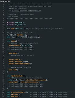
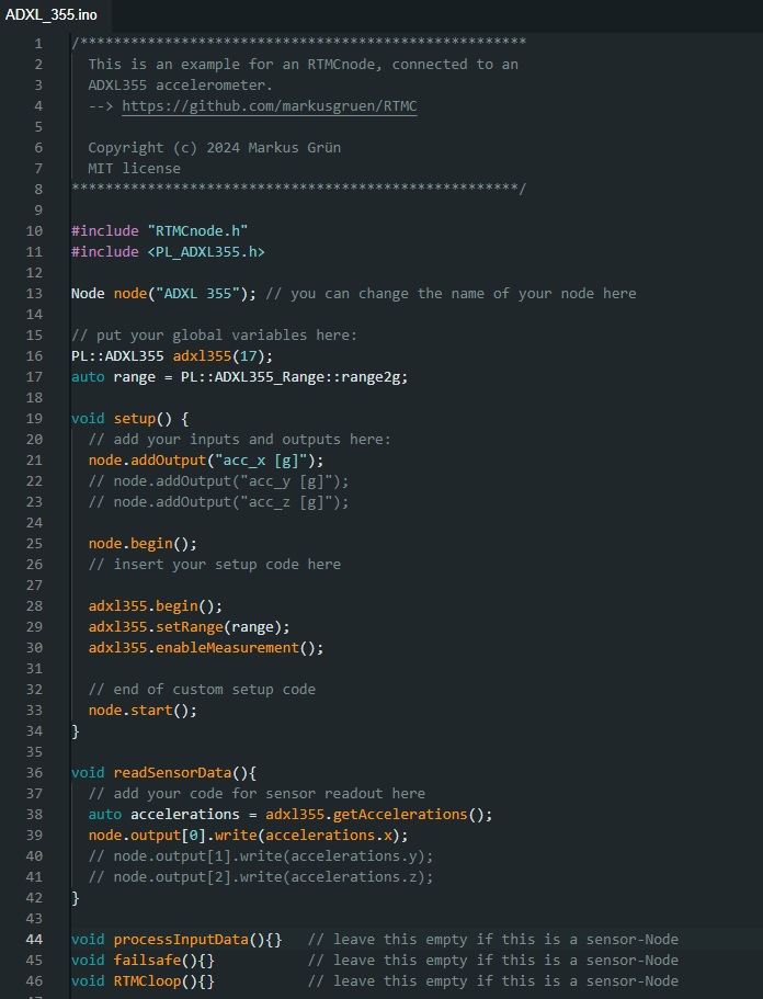
C++ Quellcode für ADXL355 Beschleunigungssensor
ADXL_355.ino // **************************************************** // This is an example for an RTMCnode, connected to an // ADXL355 accelerometer. // --> https://github.com/markusgruen/RTMC // Copyright (c) 2024
in „RTMC - universelles Multifunktions I/O, DAQ, Datenlogger“ · Projekte & Code · · Screenshots
-
Thread
schneller Quadratur-Dekoder A/B+Index mit RP2040, Arduino
andere IDEs übertragen werden. Sollte die Dateiendung aus Gründen der Kompatibilität zu Arduino auf '*.ino' umbenannt werden, muß 'rp2040_arduino.h' verwendet werden, um keine doppelten Definitionen zu erhalten.
Projekte & Code ·Mi N. · ·23 Antworten
-
Datei
PicoTerm-demo.ino
/* PicoTerm-demo zur Ansteuerung der PicoTerm-TFT Anzeige mit Text und Grafik zur Verwendung auf Arduino uno oder anderer Hardware mit ATmega328. Reines C-Programm ohne spezifische Befehle der Arduino-IDE Das Programm gliedert sich in folgende Bereiche: 1. Parametervorgabe/Init für ATmega mit UART und Timer 2. Definitionen fuer Farbe/Text/Grafik des TFT 3. Initialisierung des ATmega328 4. Basisroutinen zur TFT-Ansteuerung 5. Routinen zur Anzeige von Text und Demo-Tastatur 6. Demoprogramm unter Verwendung der vorhandenen Funktionen Michael Nowak www.mino-elektronik.de info@mino-elektronik.de 2023
in „PicoTerm-TFT, farbiges 4,3"-Terminal mit Pico-Board RP2040“ · Projekte & Code ·
-
Thread
PicoTerm-TFT, farbiges 4,3"-Terminal mit Pico-Board RP2040
, wie man das PicoTerm-TFT praktisch verwenden kann, gibt es im Anhang das Programm "PicoTerm-demo.ino", welches für einen ATmega328 geschrieben wurde. Es ist ein reines C-Programm, verwendet keine Arduino-IDE spezifischen Befehle und kann für 'gewöhnliche' Programmierung einfach in .c umbenannt werden
Projekte & Code ·Mi N. · ·4 Antworten
-
Datei
WS2812x300-Christmas.ino
#include <Adafruit_NeoPixel.h> #ifdef __AVR__ #include <avr/power.h> #endif // Which pin on the Arduino is connected to the NeoPixels? const uint8_t PIN = 6; // make sure to set this to the correct PixelPin, ignored for Esp8266 // How many NeoPixels are attached to the Arduino? const uint16_t NUMPIXELS = 300; // When we setup the NeoPixel library, we tell it how many pixels, and which pin to use to send signals. // Note that for older NeoPixel strips you might need to change the third parameter--see the strandtest // example for more information on possible values. Adafruit_NeoPixel pixels = Adafruit_NeoPixel
in „Zeigt her eure elektronischen Weihnachtsbasteleien!“ · Projekte & Code ·
-
Thread
nanoSTK, ein kleiner und schneller Programmier-Adapter für AVR-Prozessoren
Interrupt sowie SPI, Timer und Analog-IO kommen aus eigenen Modulen - es braucht nur avr-gcc - nix *.ino. Nur für die reinen Anwender, speziell die Windows-Nutzer, die sich mit Kommandozeile und "make" schwertun, gibt es im Branch "arduino_toolchain" das ganze auch "maker-gerecht" als „Sketch“ - wir
Projekte & Code ·Martin H. · ·62 Antworten
-
Datei
pt1000_rp2040_neu.ino
/* Alle Angaben ohne Gewaehr ! 2023-11-04 */ #define OFFSET 13 // 0-Offset des ADCs, Anpassung notwendig #define DEF_BAUDRATE 19200 #define ADC_MIN 0 #define ADC_MAX (4095 - OFFSET) // bei 12 Bit #define PT_IN_0 26 // analog Eingang A0 #define UNTERLAUF -99 // Fehler, auch bei Kurzschluss #define UEBERLAUF 999 // Fehler, auch bei offenem Eingang #define R_PT0 1000.0 // bei 0 Grad C #define R_REF 1200.0 // ext. Widerstand mit 0,1% #define R_ZULEITUNG 0 // bei laengeren Leitungen unbedingt anpassen #define PT_FAKTOR 3.85 // schon mit 1000.0 skaliert //#define IO_BANK0_BASE 0x40014000UL // ist auch schon
-
Thread
ESP32 in SQL DB schreiben
github.com/FredFeuerstein0815/ESP32_BME280_MariaDB/blob/main/ESP32_BME280_MariaDB_DeepSleep_30_Min.ino
Projekte & Code ·Mario S. · ·3 Antworten
-
Thread
Drehgeber und Tastenentprellung für Arduino
und > passe das auf deinen AVRxDA28 an. Ich habe mir das mal kurz angesehen, einiges aus dem .ino weggelassen (nur ein Encoder benutzt) und eine simple Ausgabe (8 Leds für die unteren 8Bit des Zählers) hinzugefügt. Dabei habe ich natürlich auch in Deine Header reingeschaut, soweit das notwendig
Projekte & Code ·Falk B. · ·37 Antworten
-
Datei
SwitchBoxMotherboard_328PB.ino
#define SCLK PIN_PC1 // connected to SRCLK orange #define LATCH PIN_PB2 // connected to RCLK white #define MOSI PIN_PE3 // connected to SER green #define MISO PIN_PC0 // connected to last Q7S blue const uint8_t shiftregistercount = 4; //actual number of 8-channel shiftregisters const uint8_t channelcount = 18; //max shiftregistercount*8 const uint8_t channelassignment[channelcount] = { //starting from 0, max shiftregistercount*8-1 18, 19, 20, 21, 22, 23, 24, 25, 26, 13, 12, 11, 10, 9, 8, 7, 6, 5 }; uint8_t outputdata[shiftregistercount]; uint8_t routputdata[shiftregistercount]; uint8_t allon[shiftregistercount
in „Universeller Schieberegister-Controller“ · Projekte & Code ·
-
Thread
RP2040 reziproker Frequenzzähler mit TDC
Segger- und > Arduino-IDE. Bei diesen Version findet sich in der Datei 'mess_fm_as65.c' bzw. *.ino noch Schmutz vom Debugging. Bitte die Zeilen 1321 und 1322 löschen oder die aktuelle Version herunterladen. Nur bei der Anzeige von "Frequenz" wurde ein Offset von 0,1 Hz addiert und damit der korrekte
Projekte & Code ·Mi N. · ·34 Antworten
-
Thread
AVR-NET-IO PlatformIO Arduino Bauumgebung
kompatibler code](https://github.com/arduino-libraries/Ethernet/blob/master/examples/WebServer/WebServer.ino). * Automatischer Upload eingestellt für [usbasp](https://m.media-amazon.com/images/I/91n8zcIcEgL.__AC_SX300_SY300_QL70_ML2_.jpg) kompatible programmer zum AVR-Net-IO ISP connector. * Nach dem

Projekte & Code ·X. H. · ·1 Antworten