-
 Bild
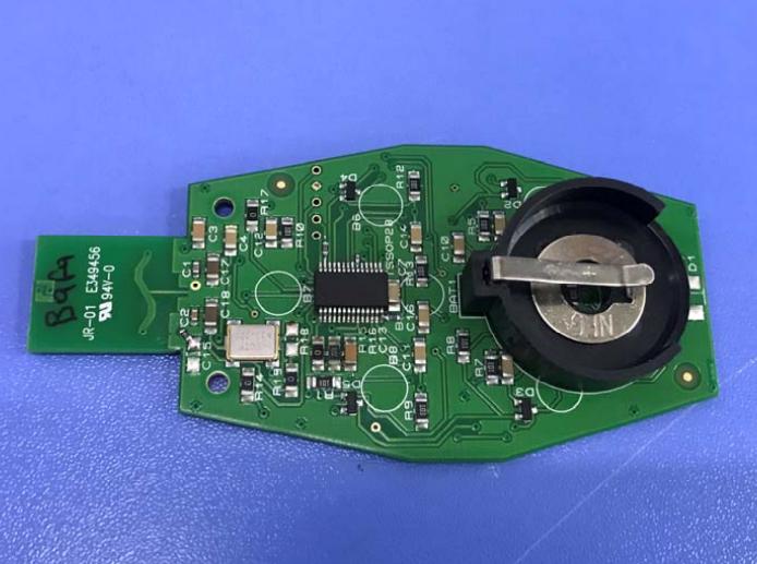
Grüne Leiterplatte mit Batteriehalter und elektronischen Bauteilen
JR-01 E349456 941-0 C1 C2 C3 C4 C10 C11 C12 C13 C14 C15 C17 C18 R1 R2 R3 R4 R5 R6 R7 R8 R9 R10 R11 R12 R13 R14 R15 R16 R17 B1 B6 D1

-
 Bild
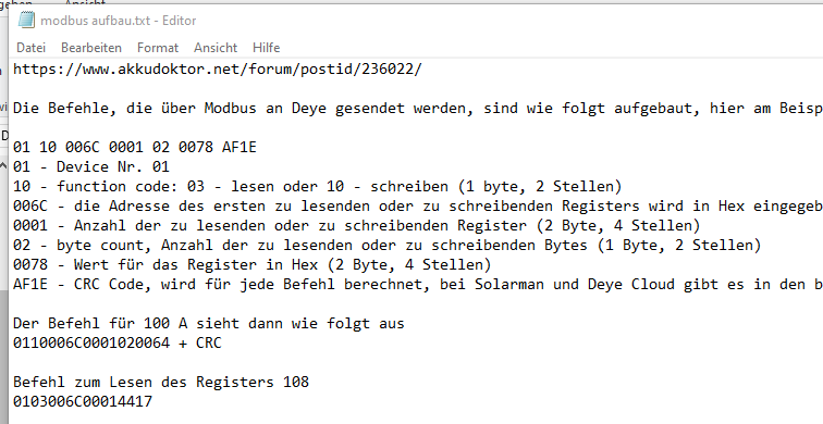
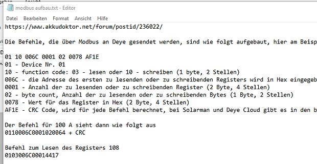
Screenshot einer Modbus-Befehlsstruktur-Erklärung
236022/ Die Befehle, die über Modbus an Deye gesendet werden, sind wie folgt aufgebaut, hier am Beisp D 01 10 006C 0001 02 0078 AF1E 01 - Device Nr. 01 10 - function code: 03 - lesen oder 10 - schreiben (1 byte, 2 Stellen) 006C - die Adresse des ersten zu lesenden oder zu schreibenden Registers wird in
-
 Bild
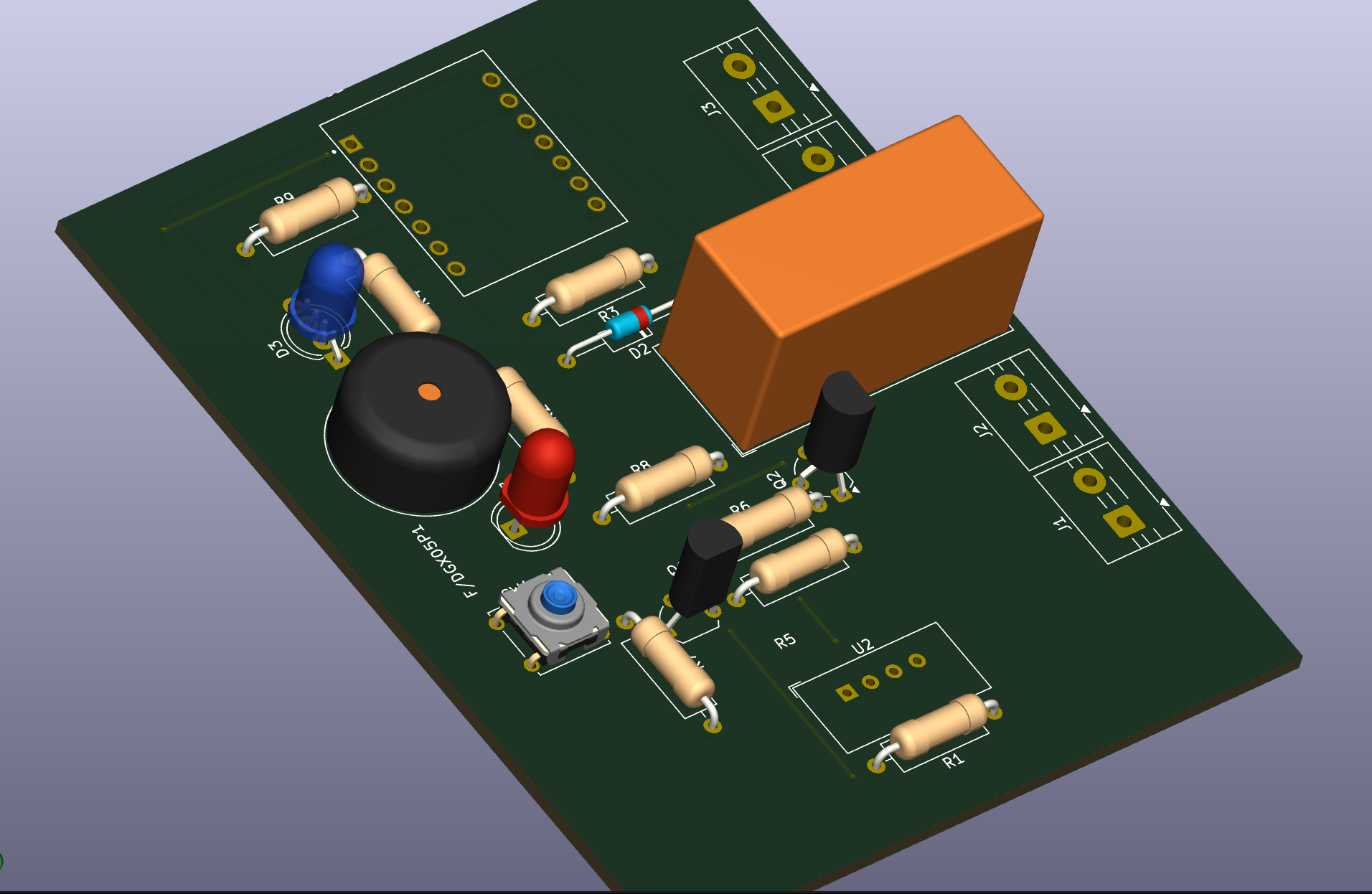
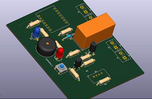
3D-CAD-Modell einer Leiterplatte mit Bauteilen
D2, R3, R8, R6, R5, R1, U2, U1, F/DGX05P1
-
 Bild
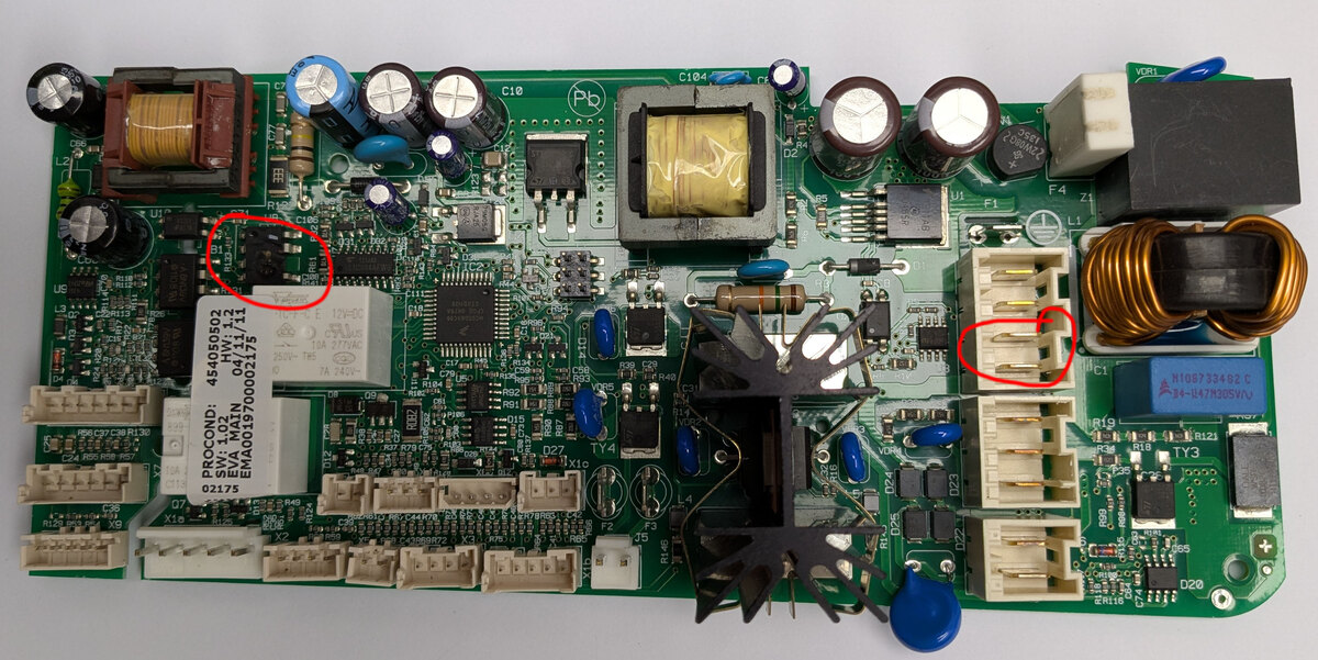
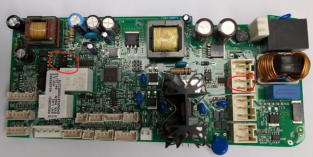
Bestückte Leiterplatte eines Netzteils
C10, C104, VDR1, US, 48405050, 04/11, EVA MAIN, 18A 274AC, 7A 242V, SW: 1.02, EVA MAIN, 03/07/2007, 02175, X15, X16, X17, X18, L1, L2, TY3, D20, N1097324 02, X4-L47H305V
-
 Bild
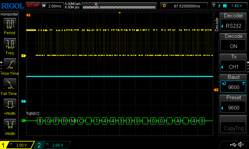
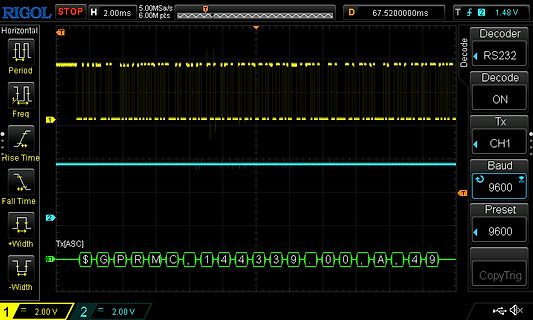
Oszilloskop-Screenshot mit RS232-Dekodierung
RIGOL STOP H 2.00ms 5.00MSa/s 6.00M pts D 67.5200000ms T 2 1.48V Period Freq Rise Time Fall Time +Width -Width Decoder RS232 Decode ON Tx CH1 Baud 9600 Preset 9600 CopyTrig 1 2.00 V 2 2.00 V $GPRMC,14439.00,A,49
-
 Bild
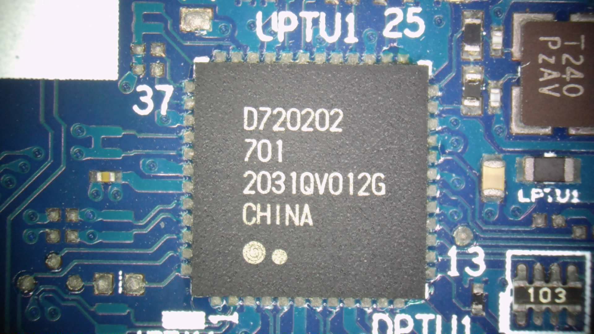
Makroaufnahme eines integrierten Schaltkreises auf Leiterplatte
UPTU1 25 37 D720202 701 2031QV012G CHINA T240 PZAV LPTU1 13 103

-
 Bild
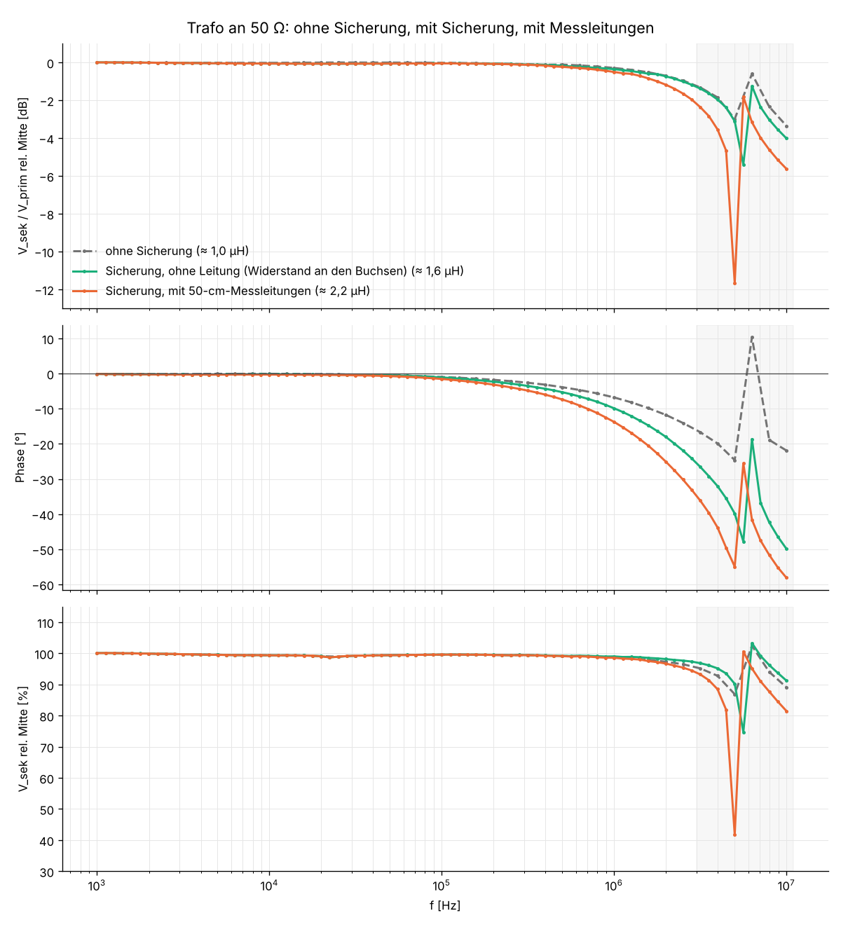
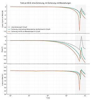
Frequenzgang-Diagramme eines Transformators mit und ohne Sicherung
Trafo an 50 Ω: ohne Sicherung, mit Sicherung, mit Messleitungen V_sek / V_prim rel. Mitte [dB] -- ohne Sicherung (≈ 1,0 µH) -- Sicherung, ohne Leitung (Widerstand an den Buchsen) (≈ 1,6 µH) -- Sicherung, mit 50-cm-Messleitungen (≈ 2,2 µH) Phase [°] V_sek rel. Mitte [%] f [Hz]
-
 Bild
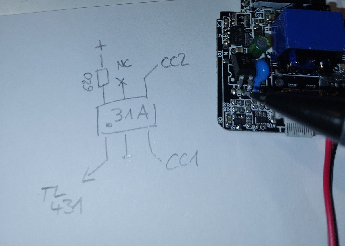
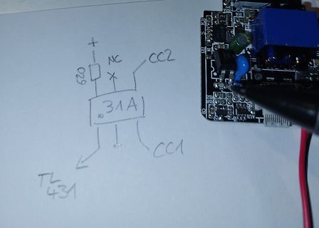
Handzeichnung eines TL431-Schaltplans und Leiterplatte
+ NC CC2 829 31A CC1 TL431 IC4 R4 D3 R12 R13 R15 AU
-
 Bild
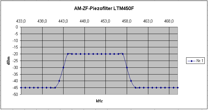
Frequenzgang eines AM-ZF-Piezofilters LTM450F
AM-ZF-Piezofilter LTM450F 433,0 438,0 443,0 448,0 453,0 458,0 463,0 468,0 0 -5 -10 -15 -20 -25 -30 -35 -40 -45 -50 dBm Nr. 1 kHz

-
 Bild
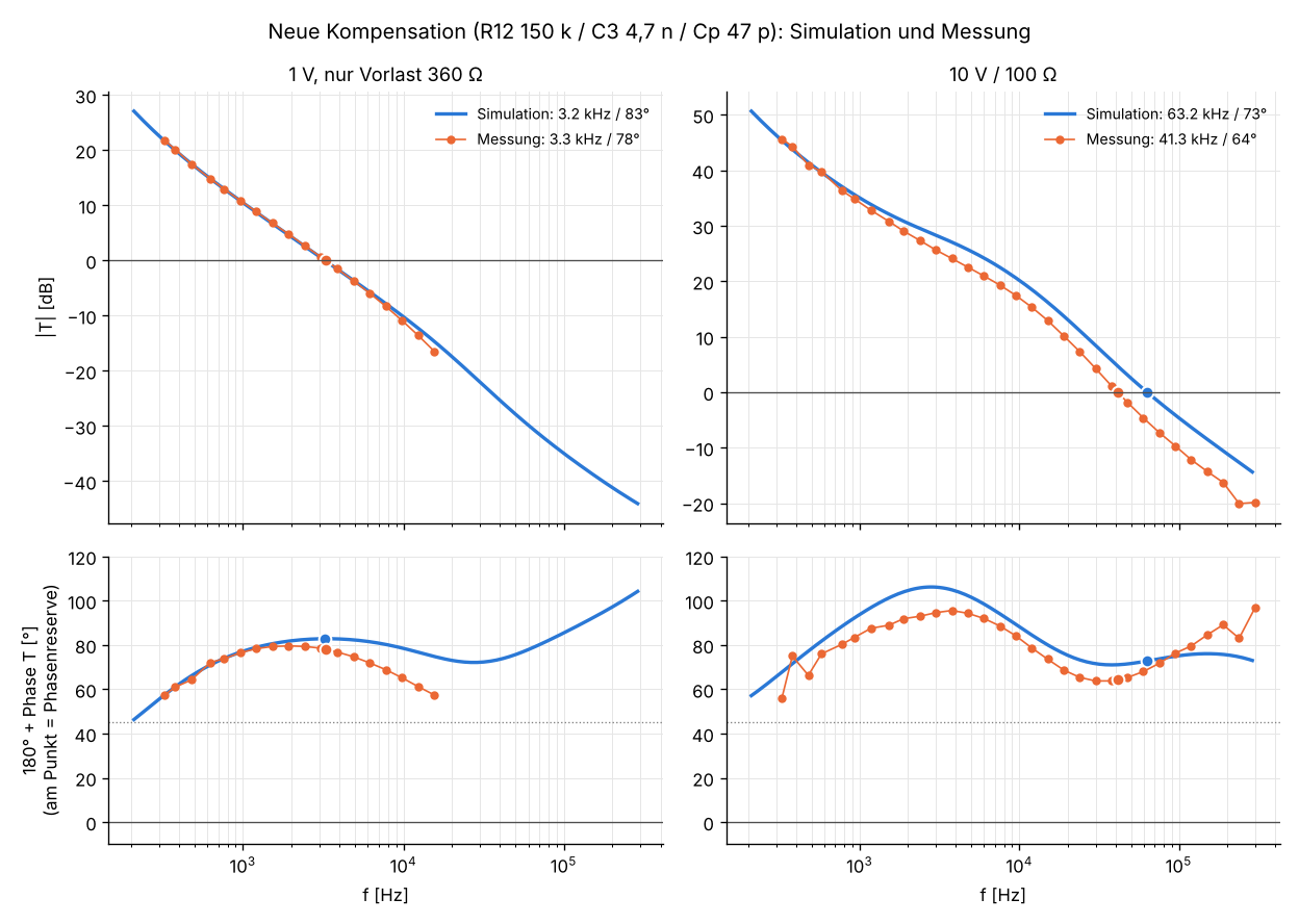
Bode-Diagramme von Simulation und Messung
Neue Kompensation (R12 150 k / C3 4,7 n / Cp 47 p): Simulation und Messung 1 V, nur Vorlast 360 Ω Simulation: 3.2 kHz / 83° Messung: 3.3 kHz / 78° 10 V / 100 Ω Simulation: 63.2 kHz / 73° Messung: 41.3 kHz / 64° |T| [dB] 180° + Phase reserve [°] f [Hz]

-
 Bild
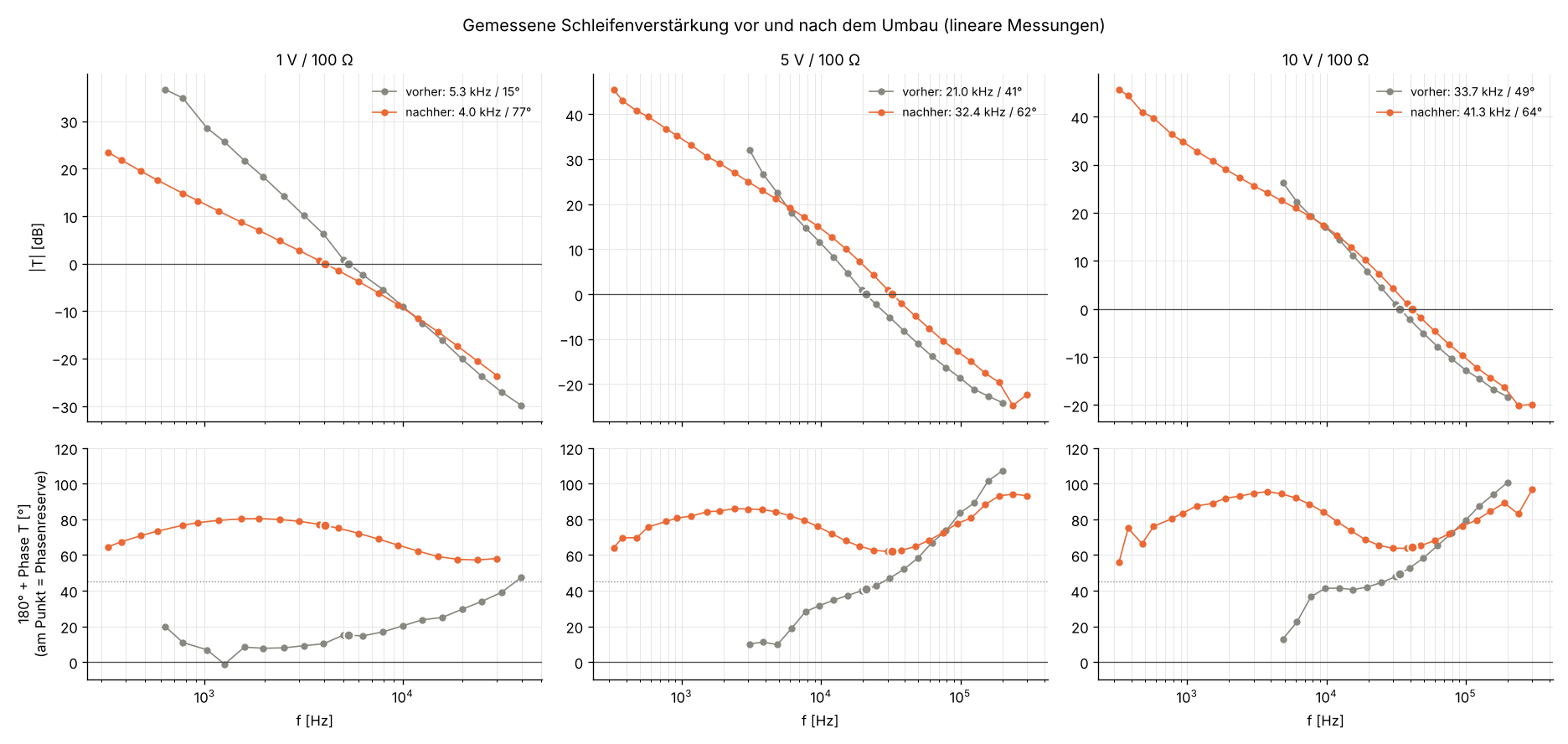
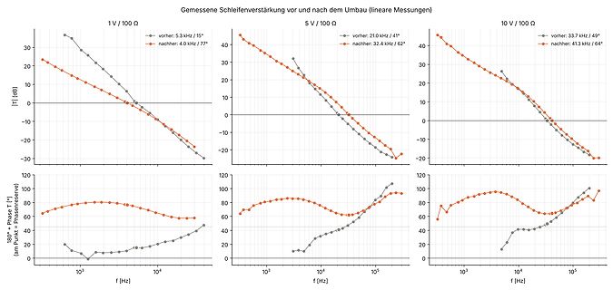
Bode-Diagramme der Schleifenverstärkung vor und nach Umbau
Gemessene Schleifenverstärkung vor und nach dem Umbau (lineare Messungen) 1 V / 100 Ω vorher: 5.3 kHz / 15° nachher: 4.0 kHz / 77° 5 V / 100 Ω vorher: 21.0 kHz / 41° nachher: 32.4 kHz / 62° 10 V / 100 Ω vorher: 33.7 kHz / 49° nachher: 41.3 kHz / 64° |T| [dB] f [Hz] 180° + Phase
-
 Bild
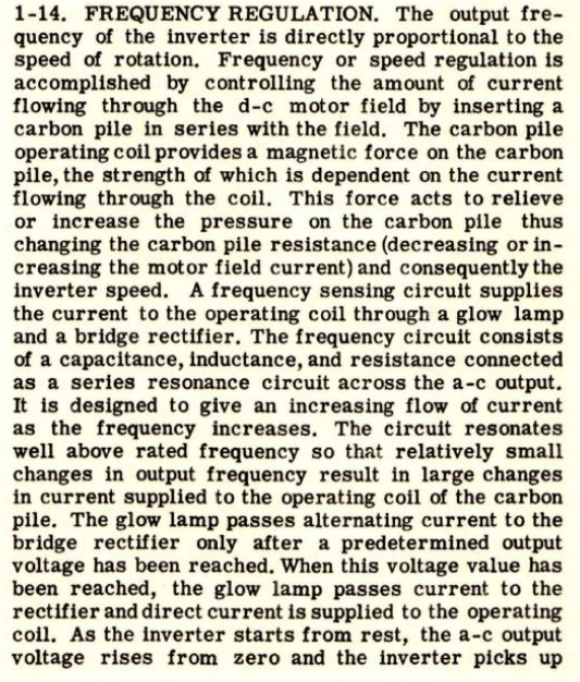
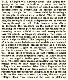
Text über Frequenzregelung eines Inverters
1-14. FREQUENCY REGULATION. The output frequency of the inverter is directly proportional to the speed of rotation. Frequency or speed regulation is accomplished by controlling the amount of current flowing through the d-c motor field by inserting a carbon pile in series with the field. The carbon pile operating coil provides a magnetic force on the carbon pile, the strength of which is dependent on the current flowing
-
 Bild
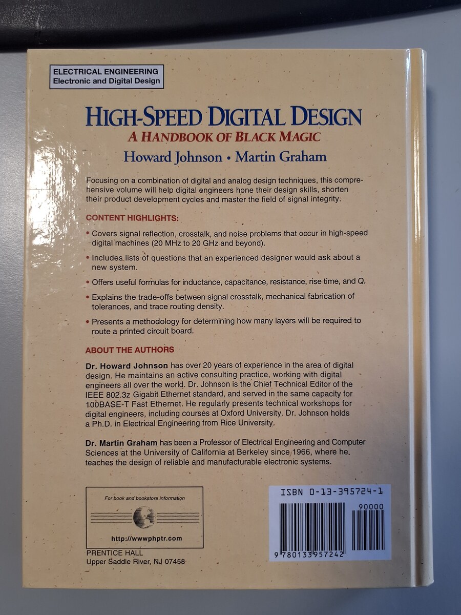
Buchcover High-Speed Digital Design
technical workshops for digital engineers, including courses at Oxford University. Dr. Johnson holds a Ph.D. in Electrical Engineering from Rice University. Dr. Martin Graham has been a Professor of Electrical Engineering and Computer Sciences at the University of California at Berkeley since 1966, where