-
PDF
NFAQ1560R43T-D.pdf
Simplified Block Diagram www.onsemi.com 3 NFAQ1560R43T PIN FUNCTION DESCRIPTION Pin Name Description 1 VSS Low−Side Common Supply Ground 2 VDD Low−Side Bias Voltage for IC and IGBTs Driving 3 HIN(U) Signal Input for High−Side U Phase 4 HIN(V) Signal Input for High−Side V Phase 5 HIN(W) Signal Input for High−
in „Bosch WAV28K40/01 Serie 8 Waschmaschine - Trommel dreht nicht - E60-09 - Inverter, LNK304, TNY88PG“ · Analoge Elektronik und Schaltungstechnik ·
-
PDF
signetics-1986.pdf
HIGH level driver (4) and the device may be impaired. Provisions should be made in system design and testing The phase splitter (2) provides the inversion LOW level driver (5) on simultaneously. to limit voltages and currents as shown be low. and amplification in the circuit. It determinesThe level shifter (3) and HIGH level driver (4) whether the outputs are active level HIGH or combine to form an emitter follower circuit active level
in „7805 als Pegelwandler?“ · Analoge Elektronik und Schaltungstechnik ·
-
Bild
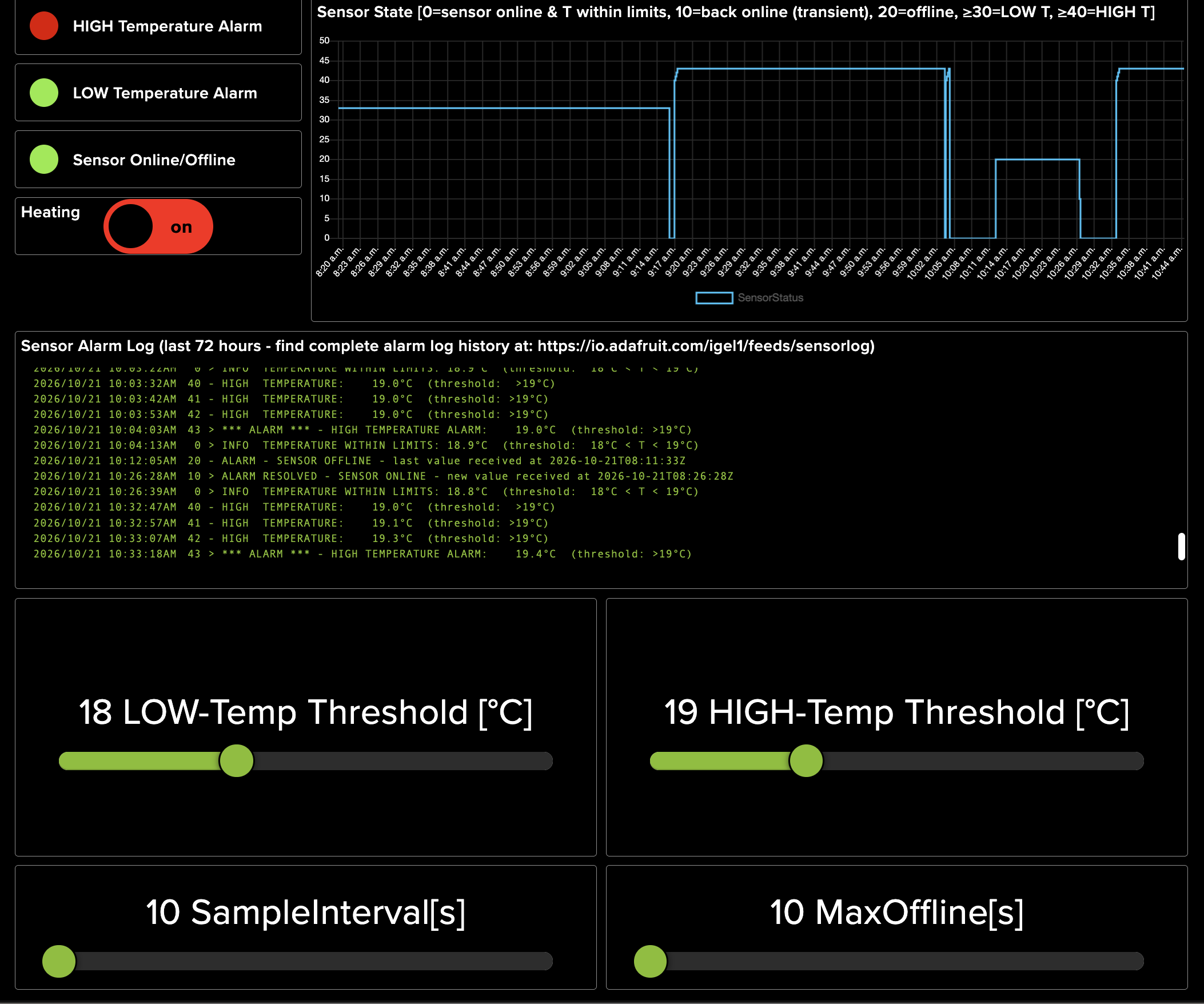
Dashboard einer Temperaturüberwachung mit Graph und Log
HIGH Temperature Alarm LOW Temperature Alarm Sensor Online/Offline Heating on Sensor State [0=sensor online & T within limits, 10=back online (transient), 20=offline, >=30=LOW T, >=40=HIGH T] SensorStatus
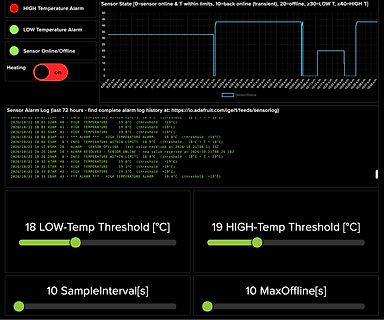
in „KiCAD: Erste Gehversuche - bitte um Feedback“ · Platinen · · Screenshots
-
Datei
Messung_der_Spannung_eines_48V_LiFePO4-Akkus_an_seinen_Polklemmen_v1.1.ino
ENTPRELL_LIM 100 // Entprellwert für Schaltschwelle #define LED_PIN PB5 // Arduino Uno Pin13 #define LED_PIN_LOW (PORTB &= ~(1<<LED_PIN)) #define LED_PIN_HIGH (PORTB |= (1<<LED_PIN)) #define LED_PIN_TOG (PORTB ^= (1<<LED_PIN)) #define LED_PIN_GET ((PINB & (1<<LED_PIN)) != 0) uint16_t adc_wert = 0, atomic_adc_wert
in „avr adc streuung ausgleichen“ · Mikrocontroller und Digitale Elektronik ·
-
Datei
Messung_der_Spannung_eines_48V_LiFePO4-Akkus_an_seinen_Polklemmen.ino
UBATTLOW_LIM 741 //ADC-Wert für Für Abschaltschwelle #define LED_PIN PB5 // Arduino Uno Pin13 #define LED_PIN_LOW (PORTB &= ~(1<<LED_PIN)) #define LED_PIN_HIGH (PORTB |= (1<<LED_PIN)) #define LED_PIN_TOG (PORTB ^= (1<<LED_PIN)) uint16_t adc_wert = 0; uint16_t counter; bool adc_wert_bereit = false; void ini(void
in „avr adc streuung ausgleichen“ · Mikrocontroller und Digitale Elektronik ·
-
Bild
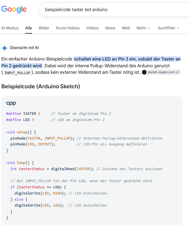
Google-Suchergebnisse für Arduino-Beispielcode
tasterStatus = digitalRead(TASTER); // Zustand des Tasters auslesen // Bei INPUT_PULLUP ist der Pin LOW, wenn der Taster gedrückt wird if (tasterStatus == LOW) { digitalWrite(LED, HIGH); // LED einschalten } else { digitalWrite(LED, LOW); // LED ausschalten }
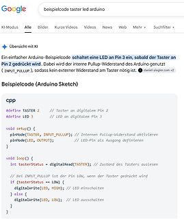
in „Einen Arduino Nano programmieren Neuling hierbei , nicht generell“ · Mikrocontroller und Digitale Elektronik · · Screenshots
-
Datei
Sensor_Auslesen_TWI.asm
- Code-Segment --- .cseg .org 0x0000 rjmp reset reset: ; 1. Stackpointer initialisieren ldi temp, high(RAMEND) out SPH, temp ldi temp, low(RAMEND) out SPL, temp ; 2. TWI-Schnittstelle initialisieren (8 MHz / (16 + 2*TWBR * Prescaler)) ; Für ~100kHz bei 8MHz: TWBR = 32, Prescaler = 1 (TWSR = 0) ldi temp
in „Unterbrechnung beim TWI sorgt für stetigen Reset (SHT41 an Atmega88)“ · Mikrocontroller und Digitale Elektronik ·
-
Bild
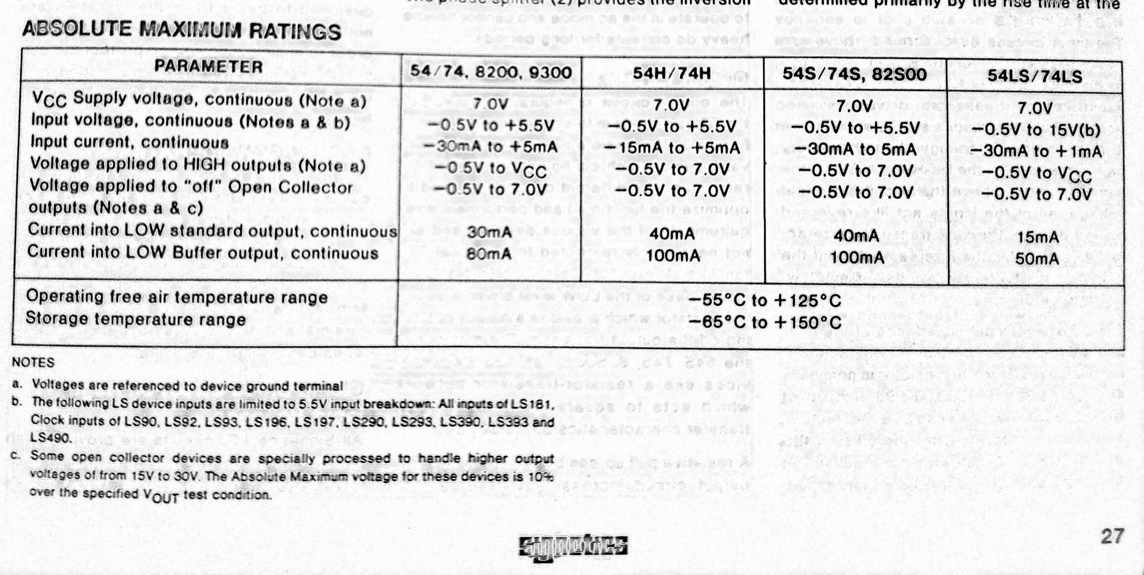
Tabelle der absoluten Maximalwerte eines Datenblatts
Input current, continuous -30mA to +5mA -15mA to +5mA -30mA to 5mA -30mA to +1mA Voltage applied to HIGH outputs (Note a) -0.5V to VCC -0.5V to 7.0V -0.5V to 7.0V -0.5V to VCC Voltage applied to "off" Open Collector outputs (Notes a & c) -0.5V to 7.0V -0.5V to 7.0V -0.5V to 7.0V -0.5V to 7.0V Current into LOW standard output, continuous 30mA 40mA 40mA 15mA Current into LOW Buffer, continuous 80mA 100mA 100mA 50mA Operating free air temperature range -55°C to +125°C Storage temperature range -65°C to +150
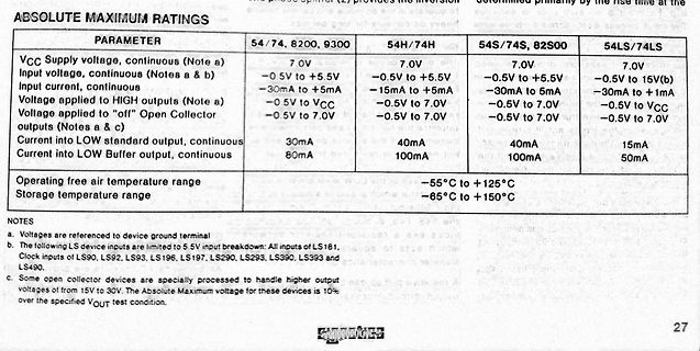
in „7805 als Pegelwandler?“ · Analoge Elektronik und Schaltungstechnik · · Screenshots
-
PDF
FT_1984_Heft_01_OCR.pdf
1029 U, S III, S IV 111-1, IV-1 7-5, 10-12 Uan6 H {>n III-2, IV-2 6-5, 11-12 L IUp) Steuerspannung HIGH: $ USH = 3,3 V Eingangssperrstrom HIGH: sh = 1 PA 11 Steuerspannung LOW: USL =2,1 V i Steuerstrom LOW: - /SL = 200 pA i Schalter- Steuerung Schaltersteuerung TDA 1029 11 11 11 Eingeschaltete Durchgeschaltete
in „[VS] verschenke Taststift“ · Markt ·
-
Bild
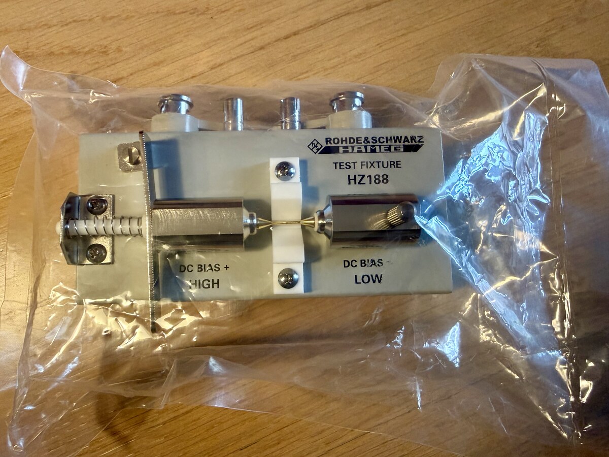
Rohde & Schwarz Hameg Test Fixture HZ188
ROHDE & SCHWARZ HAMEG TEST FIXTURE HZ188 DC BIAS + HIGH DC BIAS - LOW
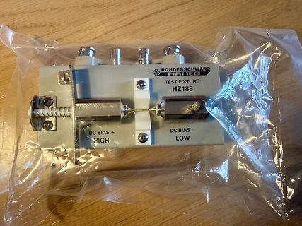
in „Verkaufe HM8118 LCR Messgerät Rohde & Schwarz / Hameg in OVP - neuwertig“ · Markt · · Fotos
-
PDF
onket_v2_schaltplan.pdf
Batteriespannung messen C C VBAT VBAT R1 R9 1M 100k PLAY-Taste zieht die Basis -> Q2 leitet -> EN high 2 R3 VBAT_SENSE KEY_PLAY Q2 R10 C5 470k 1 BC857 3 100k 100nF GND GND R4 470k TP5 D CONV_EN D R2 R5 3 Q3 1M GPIO0_PWR_HOLD 1 BC847 zu EN des Wandlers 10k R6 2 GND 100k Teiler 1:2 auf den ADC (GPIO29)
in „Review erbeten: Synthesizer mit RP2350, 2× AAA, ohne USB Erstentwurf, kein Elektronikhintergrund“ · Platinen ·