2 seconds) package then has to be sent again. bcc = 1 byte = sum of all bytes incl. <DC2>, modulo 256 <ACK> = 6(dec.) = $06 Request for protocol settings <DC2> 1 P bcc This command is used to query protocol > settings. < <ACK> max. akt. send < <DC2> 3 akt. timeout bcc packet size packet size <DC2> =
Handling. Die Datenrate deines SPI ist auch noch relevant. Da der F107 nicht zu den schnellsten gehört (max 72 MHz) wäre an der Taktfrequenz sicherlich noch eine Steigerung möglich, sowohl in in der Arbeitsgeschwindigkeit des Controllers als auch in der Taktfrequenz des SPI. Immerhin könnte man bei einem
sec annähernd erreicht. Das TI Teil hatte 128 kByte und lief bei ca. 72 MHz, Atmel bei 300 MHz und 256k. Die Buffergrössen sind wichtig wenn mehrere Router dazwischen hängen, aber auf so niedrige Werte bin ich nie gekommen. Vermutlich liegt es an der SPI Kommunikation oder Bugs. Schau dir mal das
OK, Schwurbeldieter, dann mach mir doch einfach mal seriöse Angebote für zwei SO-DIMMs, 256 MByte SDRAM. Oder für eine 10-GByte-Notebookfestplatte. Mach mal. Aber es muss sich lohnen.
zum Dauerbeschreiben mit z.B. Videos aus Überwachungskameras gedacht ist. Das Pendant von Sandisk (Max Endurance) wurde 2020 damit beworben, daß man die 64GB SD-Karte 30.000h mit Full-HD Video dauerbespielen könne. Selbst wenn das komprimiertes MP4 sein sollte, sind 3 Jahre Dauerbespielbarleit eine Hausnummer
sich vermutlich nicht über JTAG programmieren, oder? Als letzter Kandidat bleibt Altera mit der Max V Serie übrig, die Software "Quartus® Prime Lite Edition" ist aktuell und kostenlos. Programmer besorgen sollte auch kein Thema sein... VHDL geht auch. Was würdet Ihr empfehlen, Mikrochip oder Altera
#8014501: > Was würdet Ihr empfehlen, Mikrochip oder Altera? Lattice ;-) Im Ernst: der MachXO2-256 ist ideal, um ein TTL-Grab zu ersetzen. Recht günstig (so um 5$), integriertes Flash, einfach anzuschließen und mit Diamond (kostenlos und auch schlank!) zu programmieren. Als JTAG-Programmierer
Zigbee2Mqtt das Joinen aktiviert. Natürlich ist der Abstand zwischen ESP und Zigbee Stick gering (max. 1m, direkte Sicht). Und falls es irgendwie hilfreich ist: Z2M nutzt den Kanal 11. Ich habe den ESP mehrfach mit idf.py erase-flash flash monitor nach bestem Wissen neu aufgesetzt. Und im Monitor
277ad0a I (228) app_init: Compile time: Mar 6 2026 21:44:18 I (233) app_init: ELF file SHA256: 9a5966530... I (237) app_init: ESP-IDF: v5.5.2-dirty I (241) efuse_init: Min chip rev: v0.0 I (245) efuse_init: Max chip rev: v0.99 I (249) efuse_init: Chip rev: v0.2
entspricht, d.h. damit können die UART-Standardbaudraten erzeugt werden. Der Softwareteiler wird mit 256 gewählt, d.h. 256 Timerinterrupts pro Sekunde, und kann somit mit nur einem einzigen Byte realisiert werden. Für größere Werte muß der Softwareteiler als int (2 Byte) deklariert werden. Bei kleinen
haben wir ja noch mal Glück gehabt, es gibt keinen Rest bei der Division und die Sekunde ist exakt 256 * 43200 = 11059200 Zyklen lang. Theoretisch. Denn selbst wenn auf dem Quarz eine Frequenz von 11,0592 Mhz aufgedruckt ist, so schwingt er doch auf einer etwas anderen Frequenz. Der Grund dafür sind
configuration screens • Interactive web pages through the use of Java applets • E-mail • 128-, 192-, or 256-bit AES Rijndael encryption (Optional) • EMI tested and compliant • Extended operating temperature: -40 to +85˚ C normal mode -40 to +75˚ C high-performance mode • High-performance processor (12 MIPS
configuration screens • Interactive web pages through the use of Java applets • E-mail • 128-, 192-, or 256-bit AES Rijndael encryption (Optional) • EMI tested and compliant • Extended operating temperature: -40 to +85˚ C normal mode -40 to +75˚ C high-performance mode • High-performance processor (12 MIPS
zusammen benutzen kann. https://www.techpowerup.com/gpu-specs/tesla-m10.c3035 Der AMD Ryzen™ AI Max+ PRO 395 macht so um die 200GB/s auf dem Speicher und man kann eben 128GB RAM reinmachen. Allerdings kostet so ein komplett neues System natürlich auch sehr viel mehr als 200€ für eine M10.
Qwen3-coder-next 80B sollte eigentlich komfortabel auf deinen RTX-Stack passen. Achte auf ein max. Kontextfenster. Viel Spass beim Agent-Tuning ;)
primitive Weise einen Buck-Converter zusammengeklöppelt. Wie gesagt, es geht um einen Verbraucher von max. 2,4W! Es wäre aber schön gewesen, wenn es für ein paar Euro noch einfacher und klarer gegangen wäre: Ein kleines Breakout-Board, Schraubklemmen für die Leistungsseite, Stiftleiste für den Steuereingang
adjustable from 0 % to 100 % Dafür beim PCA9635: Each LED output has its own 8-bit resolution (256 steps) fixed frequency individual PWM controller that operates at 97 kHz with a duty cycle that is adjustable from 0 % to 99.6 % Letzterer ist auf Breakout-Board vielleicht nicht unmöglich, aber
können (Blackfin CPLB). Das wären die interessanten Details gewesen, neben klassischer Angaben wie f_max, BogoMIPS, usw. Dann typische Entwickler-Fragen: - Debugging: Kernel-Debugging, oder debugbare Simulationsmodelle vorliegend? (wie Renode-Cosimulation) - Board-Supply-Package: Support vom Hersteller
Linux mit X11 aehnlich schnell und brauchbar wie ein Interactive Unix auf einem 486/33. Natuerlich nur 256 Farben... .-) Interessant fuer Embeddedbetrachtungen sind aber Sharp Zaurus. Die hatten anfang der 2000er einen Intel Xscale mit 400Mhz und 640x400pixel. Da lief eine eigene Grafikoberflaeche Qtopia
, F is the Acknowledge. The master then sends the higher data byte to be IN,MAX SW written into the desired register. The ISL88731 will respond with switching frequency and I L,MAX is the max DC current in the an Acknowledge. The master then issues a Stop condition, inductor. indicating to the ISL88731 that the current transaction is For VIN,MAX = 20V, VBAT = 12.6V, IBAT,MAX = 4.5A, and complete. Once this transaction completes the ISL88731 will fs= 400kHz, the calculated inductance is 9.3µH. Choosing the begin operating at the new current
a peripheral device specially designed for I/O type MCU used to expand the display capability. The max. Display segment of the device are 256 patterns (32×8). The ET6622 is a memory mapping and multi-function LCD controller. Features ⚫ Operating voltage: 2.7V~5.2V ⚫ Built-in 32 kHz RC oscillator ⚫ 1/4bias, 1/8duty, frame frequency is 64Hz ⚫ Max.32×8 patterns, 8 commons, 32 segments ⚫ Built-in internal resistor type bias generator ⚫ 3-wire serial interface ⚫ 8 kinds of time base/WDT selection ⚫ Time base or WDT over flow output ⚫ Built-in LCD
/10 TM56E6422 Data Sheet FEATURES 1. ROM: 4K x 16 bits MTP 2. EEPROM: 256 x 8 bits 3. RAM: 256 x 8 bits 4. STACK: 8 Levels 5. System Clock type selections: Fast clock from 1~20 MHz Crystal (FXT) Fast clock from Internal RC (FIRC, 16 MHz) Slow clock from 32768 Hz Crystal
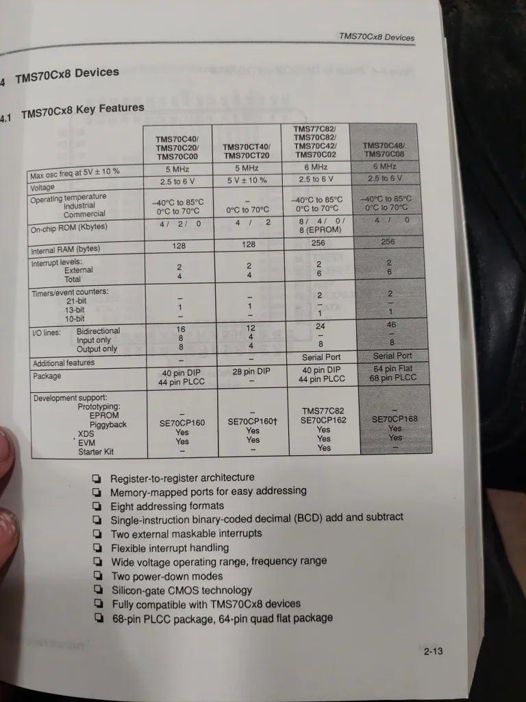
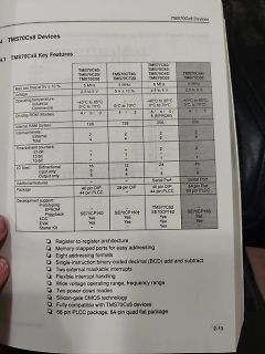
TMS70Cx8 Devices
4.1 TMS70Cx8 Key Features
TMS70C40/TMS70C20/TMS70C00
Max osc freq at 5V ± 10%
5 MHz
Voltage
2.5 to 6 V
Operating temperature
Industrial
Commercial
-40°C to 85°C
0°C to 70°C
TMS70CT40/TMS70CT20
5 MHz
5V ± 10%
128
Internal RAM (bytes)
128
256
256
TMS70C82/TMS70C82
www.mdr.de/nachrichten/sachsen/leipzig/leipzig-leipzig-land/bmw-humanoide-roboter-automatisierung,roboter-256.html Ein halbwegs realistischer Beitrag. "Humanoide Roboter sind eine Art universale Automatisierungslösung. Wie ein Schweizer Messer für die Automatisierung." Das glaubt und hofft man. Der
Märchen, von seiner SpaceX Chefin Cwen Shotwell 2018 vollmundig angekündigt. Sollte bis spätestens 2028 (max. 10 Jahre) laufen. Naja. https://youtu.be/ENBn-W3uPXQ?si=TVhut3L5n0Rinz9r Den Rest schenke ich mir mal. Nur mal so als Abschluß. SpaceX nannte für all seine Unternehmen einen totalen addressierbaren
channel_2 ; values for channels 1/2 to switch on errorCounter endc ; definitions of constant values maxActiveCounter equ 0xFF ; max value for activeCounter maxPassiveTimer equ 0xFF ; max value for TMRO during passive pulse maxErrorCounter equ 0xFF ; max. number of invalid receiver pulses ; until output
version: 1 I (198) app_init: Compile time: Dec 27 2025 14:11:52 I (203) app_init: ELF file SHA256: f2e8d38af... I (207) app_init: ESP-IDF: v5.5.1 D (211) cpu_start: calling init function: 0x42000246 on core: 0 --- 0x42000246: __esp_system_init_fn_init_efuse_show_app_info at C:/Users
/efuse/src/esp_efuse_startup.c:47 I (217) efuse_init: Min chip rev: v0.0 I (220) efuse_init: Max chip rev: v1.99 I (224) efuse_init: Chip rev: v0.1 D (228) cpu_start: calling init function: 0x42003422 on core: 0 --- 0x42003422: __esp_system_init_fn_init_heap at C:/Users/localuser
VSCode den Github-Copilot Premium mit Claude.. Da gibt es im Moment aber nur Free 0$, Pro 17$ und Max 100$ https://claude.com/pricing Ist Preminium=Pro?
einfachen Units Beim Threadripper hat es geholfen der Grafikkarte im Bios Zugriff auf die voehandenen 256 Gb Ram zu geben. Ist ne Funktion resizable Bar, oder ähnlich, was die besseren Nividia Grafikkarten unterstützen. > Harnisch ≠ Harness ... Entschuldige bitte, meine Lernkurve zeigt gerad senkrecht
15 pF LED Characteristics RED Parameter Symbol Min Tpy Max Unit Condition Forward Voltage VF 1.8 2.0 2.2 V IF=20mA Luminous Intensity Iv 100 120 150 mcd IF=20mA Peak Emission Wavelength λp 620 622.5 625 mm —— Viewing Angle 2 1/2 —— —— —— deg —— GREEN Parameter Symbol Min Tpy Max Unit Condition Forward Voltage VF 3.0 3.2 3.4 V IF=20mA Luminous Intensity Iv 400 450 600 mcd IF=20mA Peak Emission Wavelength λp 520 522.5 525 mm —— ViewingAngle 2 1/2 —— —— —— deg —— 3 / 6 http://
5V ± 10%; VPPP = VCC ) M2tCe001 Symbol Alt Parameter Test -55 (2) l-70 -80 -90 Unit Condition o Min Max s Min Max Min Max Min Max t t 55 70 80 90 ns AVQV ACC to Outputalid G = VIL - O Valid IL ) ( s ELQV tCE Chip Enable c = VIL 55 70 80 90 ns Valido Outputu o d GLQV tOE OutputEnable E = VIL 30 35 40 40
parameters M48T58, M48T58Y Table 10. Power down/up AC characteristics (1) Symbol Parameter Min Max Unit tPD E1 or W at VIHor E2 at ILbefore power down 0 µs (2) tF VPFD (max) to VPFD (min) VCC fall time 300 µs (3) M48T58 10 µs tFB VPFD (min) to SS V CC fall time M48T58Y 10 µs t V (min) to V (max) V rise time 10 µs R PFD PFD CC t V to V (min) V rise time 1 µs RB SS PFD CC trec VPFD (max) to inputs recognized 40 200 ms 1. Valid for ambient operating temperaAure: T = 0 toCC0= 4.75 to 5.5 V or 4.5 to 5.5 V (except where noted). 2. V PFD(max) to PFD(min) fall time of lessFthan t may result
1 Blink period = 1 = ---------------------- 152 PSC0 = 151 Set PWM0 duty cycle to 50 %: 80h PWM0 --256----------- PWM0 = 128 Set prescaler PCS1 to dim at maximum frequency: 00h Blink period = max PSC1 = 0 Set PWM1 output duty cycle to 25 %: 40h PWM1 ---------------- 256 PWM1 = 64 Set LED0 to LED3 on
Stromversorgungen. Wenn Wuerth noch die passenden Trafos liefert ist dann eine nette Verbesserung des MAX253. Hoffentlich baut Microchip noch eine Low Power Variante... mag! Soviel spannende neue Teile... Dankeschön!
Lead–free assembly p P -Temperature Min (T s(min) 150°C Ramp-up Critical Zone TLtoPT Pre Heat -Temperature Max (T s(max) 200°C L tL T -Time (min to max) (s ) 60 – 180 secs es(max) t Average ramp up rate (LiquidusTemp (T )A e Ramp-down 3°C/second max ps(min) to peak e Preheat T T S(max)T A Ramp-up Rate 3°C/second max -Temperature (T ) (Liquidus) 217°C 25˚C Reflow A t 25˚C to Peak -Time (min to max) (t ) 60 – 150 seconds Time (t) s PeakTemperature (T ) 260 +0/°C P Time within 5°C of actual peak 20 – 40 seconds Flow
assembly T p P -Temperature Min (Ts(min) 150°C Ramp-up Critical Zone TLtoPT Pre Heat -Temperature Max (T s(max) 200°C ) TL L -Time (min to max) (t) 60 – 180 secs ( s rs(max) Average ramp up rate (LiquidusTemp (T ) a A 3°C/second max eT Ramp-down to peak ms(min) t T Preheat T S(max)T A Ramp-up Rate 3°C/second max Reflow -Temperature (TA) (Liquidus) 217°C 25˚C -Time (min to max) (t) 60 – 150 seconds t 25˚C to Peak s Time (t) PeakTemperature (T P) 260+0/-°C Time within 5°C of actual peak 20 – 40 seconds Temperature
4 6 8 10 12 14 16 4 8 12 16 20 24 28 32 V−DOTS 16 32 48 64 80 96 112 128 32 64 96 128 160 192 224 256 1 SCREEN 2 SCREENS MD2 H L H L MD2 Input Pins for selection of number of columns MD3 H H L L MD3 Columns 32 40 64 80 FS0 H L H L FS0 FS1 H H L L FS1 Input Pins for selection of font Font 5 × 8 6 × 8
Evaluation-Boards sind diese Bauteile bereits enthalten, man muss ggf. nur noch die Verbindungen zwischen MAX232 und AVR herstellen . Der MAX232 ist ein Pegelwandler, der die −12/+12-Volt-Signale an der seriellen Schnittstelle des PCs zu den 5/0 Volt des AVRs kompatibel macht. C1 ist ein kleiner Elektrolyt-
nur bei Verwendung eines Takts von 16 MHz) steht in UBRRH eine 0, da der berechnete Wert kleiner als 256 ist und somit in UBRRL alleine passt. Beachtet werden muss, dass das Register UBRRH vor dem Register UBRRL beschrieben werden muss. Der Schreibzugriff auf UBRRL löst das Neusetzen des internen Taktteilers
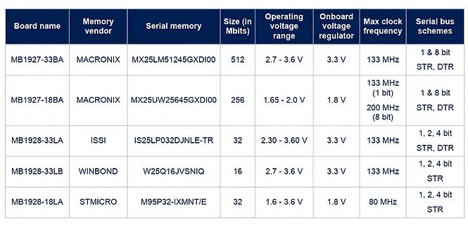
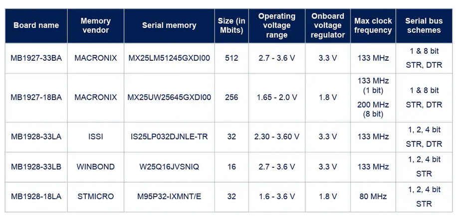
name Memory vendor Serial memory Size (in Mbits) Operating voltage range Onboard voltage regulator Max clock frequency Serial bus schemes
MB1927-33BA MACRONIX MX25LM51245GXDI00 512 2.7 - 3.6 V 3.3 V 133 MHz 1 & 8 bit STR, DTR
MB1927-18BA MACRONIX MX25UW25645GXDI00 256 1.65 - 2.0 V 1.8 V 133 MHz (1 bit
electric reset circuit and power lost reset circuit. Each pixel of the three primary color can achieve 256 brightness display, completed 16777216 color full color display, and scan frequency not less than 400Hz/s. Cascading port transmission signal by single line. Any two point the distance more than

 Bild
Bild
 Bild
Bild
 Bild
Bild
 Bild
Bild