also have to * * consider the automatic use of the new units by system- level design tools, such as high-level language to hardware compilers [1]. In general, realizing all required multiply-add e f g + (MA) operations by very fast (low latency, high throughput) * * implementations is not efficient, as
www.belling.com.cn 2 BL8028 ENLK EN leakage current 1 uA T SS Soft start time 0.3 ms V EN_H EN input high voltage 1.2 V V EN_L EN input low voltage 0.5 V T SD Thermal shutdown temp 160 °C TSH Thermal shutdown hysteresis 15 °C ELECTRICAL PERFORMANCE Tested under T A25 C, unless otherwise specified. Efficiency
characteristics.’) 2.1 Write data - The data to be written should be set on D0 - 7 and C/\D taken low, /WR taken low (/RD should be high) /CE pulsed low for greater than 80ns 2.2 Read data - C/\D take low, /RD take low (/WR should be high) /CE take low After 150ns read the data on D0-7 /CE take high 2.3 Write Command - To Write a Command - The command should be set on D0 - 7 and C/\D taken high, /WR taken low (/RD should be high) /CE pulsed low for greater than 80ns 2.4 Read Status - To check the Status of the T6963C controller - C/\D take high, /RD take low (/WR should be high) /CE take low
HIGH level driver (4) and the device may be impaired. Provisions should be made in system design and testing The phase splitter (2) provides the inversion LOW level driver (5) on simultaneously. to limit voltages and currents as shown be low. and amplification in the circuit. It determinesThe level shifter (3) and HIGH level driver (4) whether the outputs are active level HIGH or combine to form an emitter follower circuit active level
OB2502x High Precision CC/CV Primary-Side Power Switch GENERAL DESCRIPTION FEATURES OB2502x is a high performance offline PSR power Primary-side sensing and regulation without switch for low power AC/DC charger
als sicher gedrückt gilt, wenn der Status fünf (einstellbar) Aufrufe lang immer aktiv war (ob das low oder high aktiv ist, legt man selbst für jede Taste fest). Oder dass sie nach 20 Aufrufen als "lang" gedrückt gilt oder dass nach 20 Aufrufen Repeat beginnt. Das Timing von Repeat ist dann auch einstellbar
Allein die Schleife hier: [c] for (byte n = 0; n < 5; n++) { if (digitalRead(keyPins[n]) == LOW) keys |= (1 << n); } [/c] Braucht ein Vielfaches an Rechenzeit. Wenn du die Eleganz des Originals beibehalten willst: `keys = REG_READ(GPIO_IN_REG);` Wenn die dir egal ist (Weil
preset’ and ‘count’ modes seen, the circuit has two inputs, one for by means of S2, whilst S3 switches low frequency signals and another for between the ‘up’ and ‘down’ count high frequency signals. The low fre- modes. quencyrangecovers 20 Hz to 10 MHz and has an input impedance of ap- proximately1M£2. The
N0 X1 X0 ACK FM – High Order Bits 0 TPEN N11 N10 N9 N8 N7 N6 ACK NOTES: 1.C0 and FL: Low Order Bits and C1 and FM: High Order Bits. 2.VDM0–2: Video Mod Depth control bits (for MC44355 VMD0–2 are Don’t Care). 3.SFD0–1: Sound
is selected or when requested through the calibration menu. CH A HBW Low-Pass R Data Filter High BW A/D L Data Clamp Convert CLK Low-Pass R Offset CH B HBW Filter L Offset 12.288 MHz Unity-Gain CH A HIRES Buffer Low-Pass R Offset Filter Clamp L Offset Low-Pass Unity-Gain
ME6211 High Speed LDO Regulators, High PSRR, Low noise, ME6211 Series General Description Features The ME6211 series are highly accurate, low Maximum Output Current: 500mA noise, CMOS LDO Voltage Regulators. Offering low (V =IN3V,V OUT=3.3V) output noise, high ripple rejection ratio, low dropou Dropout Voltage: 100mV@ I =100mA OUT and very fast turn-on times, the ME6211 series is Operating Voltage Range: 2V~6.0V
port for Infineon PSOC Edge microcontrollers. This is a bare-metal port using CMSIS 6 and a set of low-level HAL submodules from Infineon's Modus Toolbox. It uses the standard ARM toolchains and builds with make. It currently supports a UART REPL, a filesystem (using QSPI flash), machine Pin, UART and
the setup to the specific hardware: Radxa Dragon (Q6A & Q8B): Flashes directly to high-speed UFS storage, setting up the board’s custom UEFI boot environment. (Note: Users will need to enter the UEFI menu and set the boot order manually after flashing to boot from UFS). Arduino Qualcomm
QN8027 High Performance Digital FM Transmitter for Portable Devices ________ General Description ________ ___________ Key Features __________ • Worldwide FM Band Transmit The QN8027 is a high performance, low power
short and wide. major concerns for portable device, such as ¾ SW node of DC-DC converter is with high MT3608 used for mobile phone. The inductor frequency voltage swing. It should be kept at should have low core loss at 1.2MHz and low a small area. DCR for better efficiency. To avoid inductor ¾ Place
data transmission time : Name Min. Standard Max. Unit value T Code period 1.20 -- -- µs T0H 0 code, high level 0.2 0.3 0.4 µs time 0 code, low level T0L time 0.8 0.9 1.0 µs T1H 1 code, high level 0.6 0.65 1.0 µs time 1 code, low level T1L time 0.2 0.55 0.6 µs Reset code low Trst level time >80 -- -- µs 1. The protocol uses a unipolar zeroing code. Each symbol must have a low level. Each symbol in this protocol starts with a high level. The high time width determines the "0" or "1" code. . 2. When writing programs, the minimum symbol period is 1.2μs. 3. The high time of
i2cbyte ;lastkey = 255 ;hi2cout 0,(key) ;hi2cout (key) dieser Port main: key = 255 for row = 0 to 5 high B.0 high B.1 high B.2 high B.3 high B.4 high B.6 select case row case 0 low B.0 case 1 low B.1 case 2 low B.2 case 3 low B.3 case 4 low B.4 case 5 low B.6 endselect pause 1 if pinC.0 = 0 then col =
4.2V. (Pin6): Open Drain Charge Status Output When the battery Charge Termination, the pin is pulled low by an internal switch, otherwise pin is in high impedance state. (Pin7): Open Drain Charge Status Output When the battery is being charged, the pin is pulled low by an internal switch, otherwise pin is in high impedance state. CE(Pin8): Chip Enable Input. A high input will put the device in the normal operating mode. Pulling the CE pin to low level will put the YP4056 into disable mode. The CE pin can be
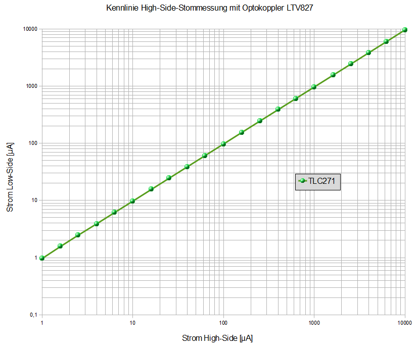
Ladungsverstärker, Instrumentenverstärker, ....). Alles mit Antenne oder Ton lieber symmetrisch. Und für die High-Side Strommessung mit OP und Transistor brauchst Du quasi einen anderen OP, der auf der High-Side an seinen Rail kommt (Ja, es gibt auch Rail to Rail, aber die kommen mit anderen Nachteilen) Früher
Instrumentenverstärker, ....). > > Alles mit Antenne oder Ton lieber symmetrisch. Und für die High-Side > Strommessung mit OP und Transistor brauchst Du quasi einen anderen OP, > der auf der High-Side an seinen Rail kommt (Ja, es gibt auch Rail to > Rail, aber die kommen mit anderen Nachteilen
Hier sind ein paar Tips zur Messung: https://www.flir.com/de-de/discover/rd-science/use-low-cost-materials-to-increase-target-emissivity/
Übersetzung.. hier der Link zum englischen Artikel: https://www.flir.com/discover/rd-science/use-low-cost-materials-to-increase-target-emissivity/ HTH und nix für Ungut
has higher impact with 4 programmed levels MLC can store twice the bits per square mm Cost high medium low silicon Swissbit AG Revision: 1.04 Industriestrasse 4 TLP: Swissbit public Template: Doc-4991 CH-9552
to 47μF)for a bootstrap. In this case, a bottom element is turned ON (setting LIN1 to LIN3 in the lower side control signal input block to high) to charge CB. (When not using bootstrap circuit, each upper side pre-drive power supply needs an independent power supply. Externally set.) In addition, please
> Das ist nun einmal der Preis für die höhere Güte. Aber ist trotzdem kacke weil das bei LowPower extrem nervt. Kann dann zielfuehrend sein den internen RC zu nutzen und den nur gelegentlich mit einem externen Quarz zu kalibrieren. Ausserdem sind Quarze auch manchmal doch wenn du starke Vibrationen
sie eben hat! Die SAMS7 SAME7 oder SAMV7 sehe ich als tot an. Auch tummeln sich in dem Bereich "high performance" PIC32. Ob die langfristig eine Daseinsberechtigung haben bzw. gegen die STM32 anstinken können? Die SAM3 oder SAM4 werden im Mittelfeld noch gelistet, sind aber auch tot. Den unteren
wie bei anderen Controllern. Man merkt aber auch das sie bestimmte Sachen nicht so konnten, wie z.B LowPower und ADCs. Also das analoge Leben halt.... Vanye
the transition on the DMA line and release the bus. This requires: 25 ns ’LS244 output disable from low level 5 ns ’S02 low to high level output transition 30 ns delay from DMA negative edge before driving address bus The 30 ns wait will also work on the Apple ][, since it only needs 27 ns (’LS04 and
müssen also soweit verstärkt werden, das die LED im Optokoppler sicher leuchtet, wenn der Port auf high geht. Vermutlich macht man das am einfachsten mit einem nicht-invertierenden Buffer hinter den 2k2 Pullups. Das kann man mit ULN2003 machen, aber dazu müssen die Optokoppler-LED einseitig auf Plus
eingeschaltet werden, dann kann doch der ULN überhaupt erst durchschalten wenn drain nicht aktiv (also High), oder funktioniert die Dunkeltastung indem die Pullups abgeschaltet werden?
Busch-Mueller-Ixon-IQ-Speed/205419 Der hat einiges an Elektronik in sich: 2 Beleuchtungsstufen High/Low, merkt sich den letzten Betriebszustand, "erschnüffelt", ob der Akku schwächelt und schaltet ggf. auf Low. ==> Unstete Versorgung aus einem Dynamo könnte ihn schon durcheinander bringen. Der alte
temperature variations, initial tolerance and loading. DC DC DC Note 5: Accuracy is guaranCLKd640 kHz. At higher clock frequencies accuracy can degrade. For lower clock frequencies, the duty cycle limits can be ex- tended so long as the minimum clock high time interval or minimum clock low time interval is no
programmer with UART connection • PowerIO Shield - Extended power capabilities with six 3A high-side switches at up to 48V • Arduino headers - Compatible with a wide range of Arduino shields and accessories [/c] Unter https://mercedes-benz.github.io/ardep/samples/uds/README.html findet
including PicoBNC+ and some active probes — are scaled incorrectly. In some cases, readings register lower than the true value, so a potentially hazardous measurement can appear safe. If you installed the ARM version of PicoScope 7, upgrade to 7.2.24 Stable or 7.2.26 EA (Early Access) — or any later
auseinander. Ich dachte anfangs das ich sowas nehme und so anschließe.: Bei NPN LOF bzw. BEI PNP High NPN-Variante (LOW-Trigger): Braun → DC+, Blau → DC−, Weiß → DC−, Grün → IN, Jumper/Schalter auf LOW. Ausgang zur Steuerung: COM + NO ⇒ potenzial schliesser den ich brauche. https://www.amazon.de
low ESR and high RMS ripple current rating. These D capacitors enable the design of ultra-compact chargers and adapters. PI-8393-051818 Typically, 200 mF to 300 mF of aluminum-polymer capacitance per ampere
copper conductor integrated into the package making it Single 5V Supply Operation suitable for both high-side and low side bi-directional current Low power consumption (6.5mA typical) sensing. The high bandwidth of 1.5MHz (3dB) and low Zero-Current Reference Pin (Vref) phase delay makes it ideal for
selected, the IM0 pin is used as the ID setting for a device code. CS* 1 I MPU Selects the HD66766R: Low: HD66766R is selected and can be accessed High: HD66766R is not selected and cannot be accessed Must be fixed at GND level when not in use. RS 1 I MPU Selects the register. Low: Index/status High: Control
following takes PWM0 as an example for description. The 16-bit PWMPRD, PWM0D registers both have a low byte and high byte structure. The high bytes can be directly accessed, but the low bytes can only be accessed via an internal 8-bit buffer, reading or writing to these register pairs must be carried
415wp-pv-modul-blackwhite-monokristallin.html Die Preise, die deutsche Hinterhof-Zubehörlieferer für ihren lowest tech Scheiss verlangen sind aberwitzig gegenüber dem was man für das Geld aus China für high tech bekommt. 4 Gehwegplatten, 4 Blechwinkel, 1m Aluprofil und ein paar Schrauben ist alles was man zum
415wp-pv-modul-blackwhite-monokristallin.html > > Die Preise, die deutsche Hinterhof-Zubehörlieferer für ihren lowest tech > Scheiss verlangen sind aberwitzig gegenüber dem was man für das Geld aus > China für high tech bekommt. > > 4 Gehwegplatten, 4 Blechwinkel, 1m Aluprofil und ein paar Schrauben ist >
function Explanation Low voltage protection Below the minimum voltage value for normal operation of the inverter. Overload protection The load exceeds the rated overpower. High voltage protection Higher than the maximum voltage
Input. The FB voltage is 0.6V. Connect a resistor divider to FB. Regulator On/Off Control Input. A high input at EN turns on the converter, and a 4 EN low input turns it off. When not used, connect EN to the input supply for automatic startup. Input Supply Pin. Must be locally bypassed. 5 IN 6 NC NC SD
wurde, habe ich rausgelesen das da ein Transistor im SoC stirbt und das Signal daher nicht mehr ganz low wird. Mit dem Widerstand belastet man den anderen Highside-Transistor mehr, zudem kann ich mich nicht erinnern ob es eine Begründung gab warum ausgerechnet nur dieser eine von Millionen Transistoren
Nein. Das Problem ist, dass der CMOS-Treiber für das Clock-Signal "ausleiert". Es kann sowohl die High-Side als auch die Low-Side treffen die zuerst den Geist aufgibt, das ist bei jedem Exemplar anders. Wenn es eine Maschine getroffen hat, kann man meist die schwache Seite mit einem Pullup oder Pulldown
internal clock sources can be used as a reference to the internal PLL in order to generate even higher frequencies. The PLL is covered in the High-frequency PLL Option section. Ultra-low Power 32kHz RC Oscillator The Ultra-low Power 32kHz internal RC oscillator (ULP32K) is mainly used for system purposes
Parameter Symbol Test Level Min Typ Max Unit Clock frequency fPCLK I 0.5 1 2 MHz Clock pulse width (high) tHCLK I 250 ns Clock pulse width (low) tLCLK I 250 ns Clock setup time (high)/reset falling edge tSetup I 0 ns No data change tNOOE IV 100 ns Reset pulse width high tHRST IV 50 ns Table 9. 3.3V ±10%
Cycle Wake-Up sequence 250ET Dead Time 258xTE LOGIC 0 LOGIC 1 TE VPWM BIT ENCODING: on Transition Low to High TBP TBP 2XE LOGIC 0 LOGIC 1 on Transition High to LowE TE TBP T BP 2XTE CODE WORD: T BP 1 6 10 SPM=1 SPM=0 Guard 18xTE Preamble 10xTE Sync 10xTE Header Encrypted Portion Fixed Code Portion Time
sich bewerkstelligen lassen. Je nach Logikanalysator kann ich gegebenenfalls auch direkt von CAN-High zu GND messen. Hat das schon jemand getestet? Fall ja, mit welchem Logikanalysator? Der Logikanalysator muss das Protokoll analysieren und an einen Rechner streamen. Mit freundlichen Grüßen Guido
sich bewerkstelligen lassen. Je nach > Logikanalysator kann ich gegebenenfalls auch direkt von CAN-High zu GND > messen. Hat das schon jemand getestet? Mach das nicht. Das ist Pfusch. Die meisten Logic Analyzer sind für Logiksignale ausgelegt. Außerdem können CAN_H und CAN_L unterschiedliche Pegel
175 mA 700 ns R LED ILED= 80 mA 440 TF LED fall time ILED= 175 mA 360 ns ILED= 80 mA 320 TLO EN/PWM low time 1 ms T HI EN/PWM high time 5 ms T PWRDWN EN/PWM low time to shutdown delay 4 8 ms THI TPWRDWN TLO EN/PWM SHUTDOWN POWERDOWN SHUTDOWN 0 mA TP2 T 1.2 V F ILED+ 100 T PS TP1 TR RSET 90% LED CURRENT
than 4 diodes, and a rectification controller IC for use with an external FET, suitable for either high-side or low-side rectification. The RVS002 integrates two N-channel MOSFETs and two Schottky diodes in a DFN2*2 package to create a low-loss full bridge rectifier capable of handling up to 3W.
conversion applications. The rectification IC is self-powered from a single AC input allowing either high side or low side rectification. The controller supports both CCM and DCM operation and is compatible with both QR and active clamp flyback topologies. . . . The RVPWxxx series flyback power ICs
protection and energy saving, high brightness, scattering angle is large, good consistency, low power, long life and other advantages. The control chip integrated in LED above becoming more simple circuit, small volume, convenient installation

 Bild
 Bild