-
 Bild
Bild
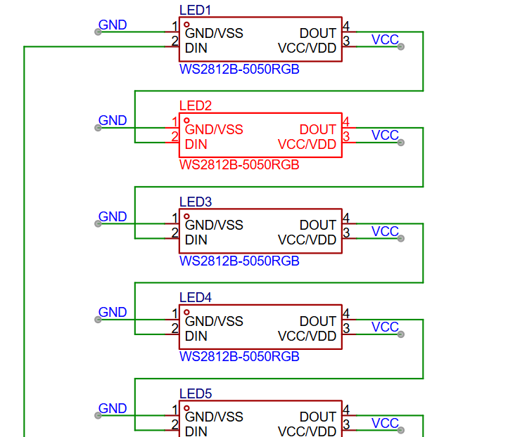
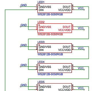
Schaltplan mit fünf WS2812B-5050RGB LEDs
LED1 WS2812B-5050RGB GND/VSS DIN DOUT VCC/VDD VCC GND LED2 WS2812B-5050RGB GND/VSS DIN DOUT VCC/VDD VCC GND LED3 WS2812B-5050RGB GND/VSS DIN DOUT VCC/VDD VCC GND LED4 WS2812B-5050RGB GND/VSS DIN DOUT VCC/VDD VCC GND LED5 WS2812B-5050RGB GND/VSS DIN DOUT VCC/VDD VCC GND
-
 Bild
Bild
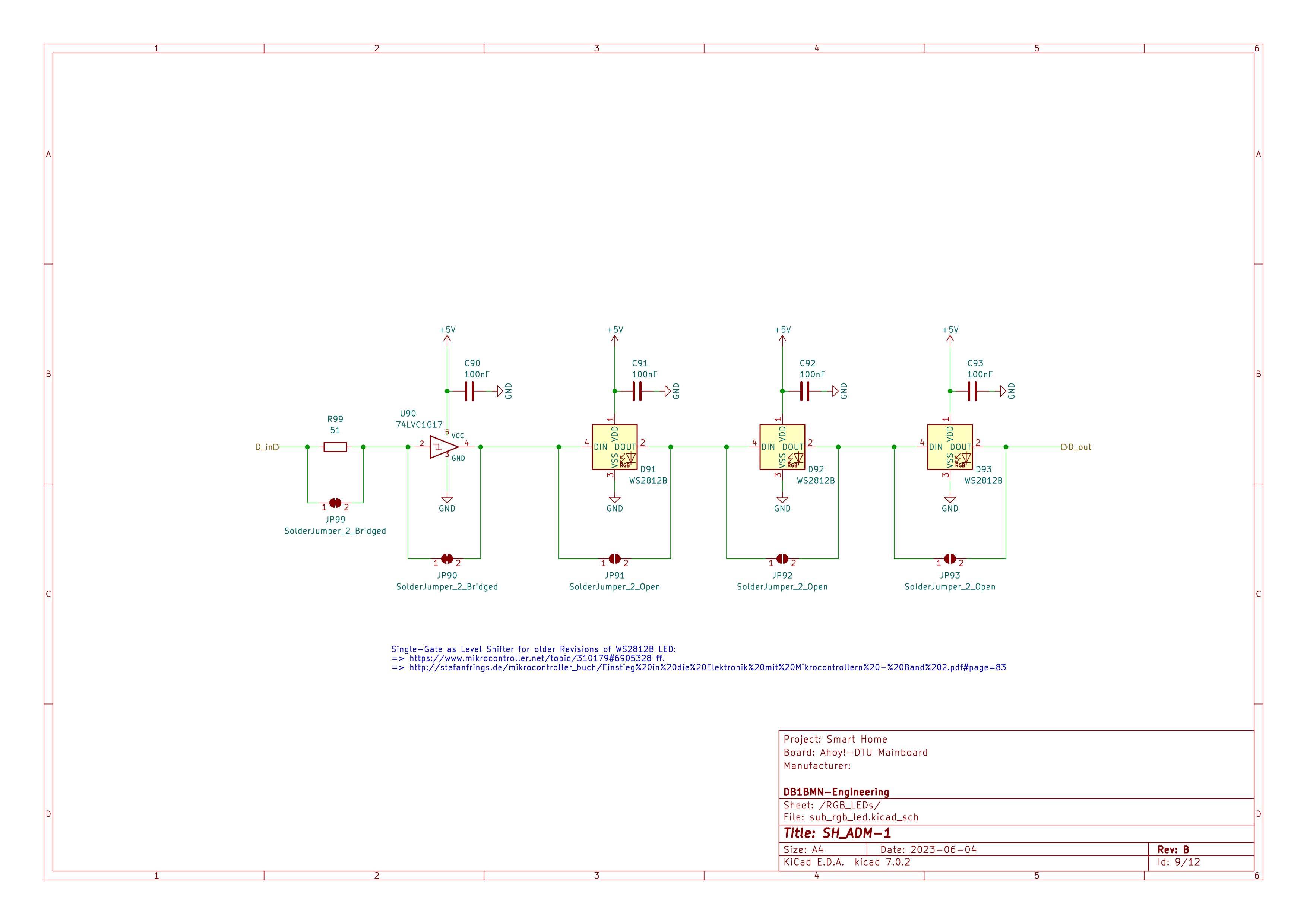
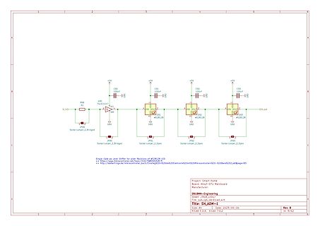
Schaltplan eines LED-Treiberschaltkreises
S1, U90 74LVC1G17, D_in, GND, +5V, C90 100nF, JP99 SolderJumper_2_Bridged, JP90, C91 100nF, D91 WS2812B, DIN, DOUT, JP91 SolderJumper_2_Open, GND, C92 100nF, D92 WS2812B, DIN, DOUT, JP92 SolderJumper_2_Open, C93 100nF, D93 WS2812B, DIN, DOUT, D_out, Project: Smart Home, Board: Anydot-DTU Mainboard,
-
 Bild
Bild
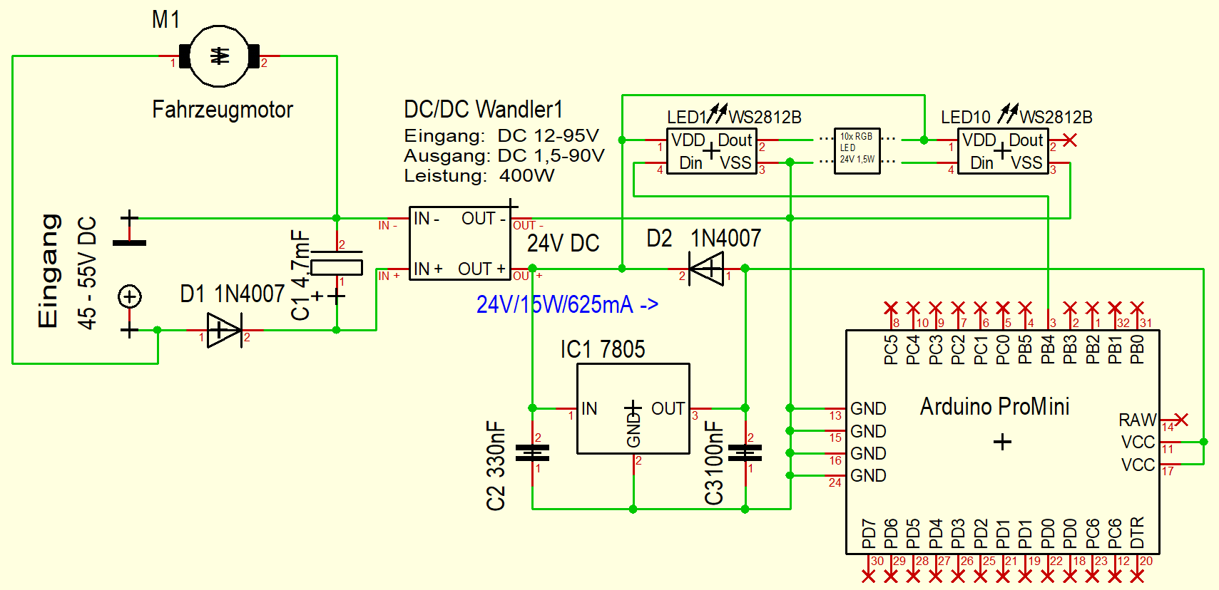
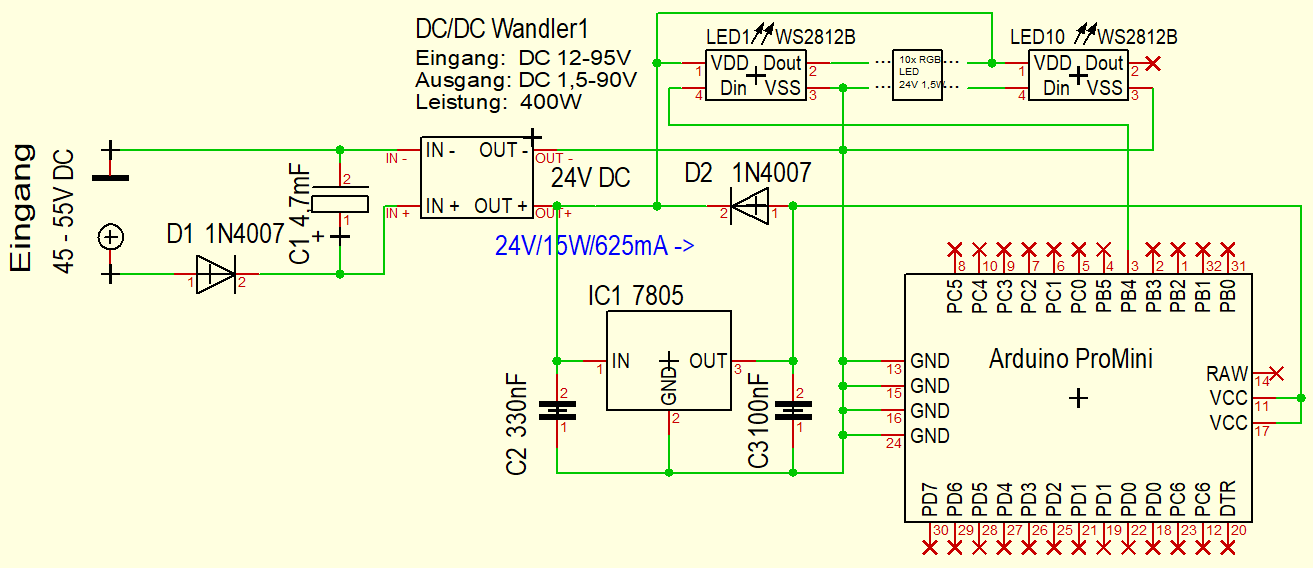
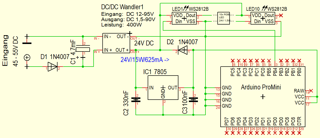
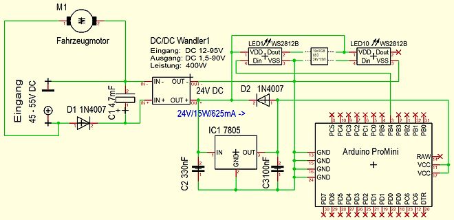
Schaltplan mit DC/DC-Wandler, Motor und Arduino ProMini
M1 Fahrzeugmotor, DC/DC Wandler1, Eingang: DC 12-95V, Ausgang: DC 1,5-90V, Leistung: 400W, LED1 WS2812B, LED10 WS2812B, 24V 1,5W, Eingang 45-55V DC, D1 1N407, C1 4,7mF, 24V/15W/625mA, D2 1N407, IC1 7805, C2 330nF, C3 100nF, Arduino ProMini, PC5 bis PC0, PB5 bis PB1, PB0, RAW, VCC, DDR, DT, PD0 bis PD7
-
 Bild
Bild
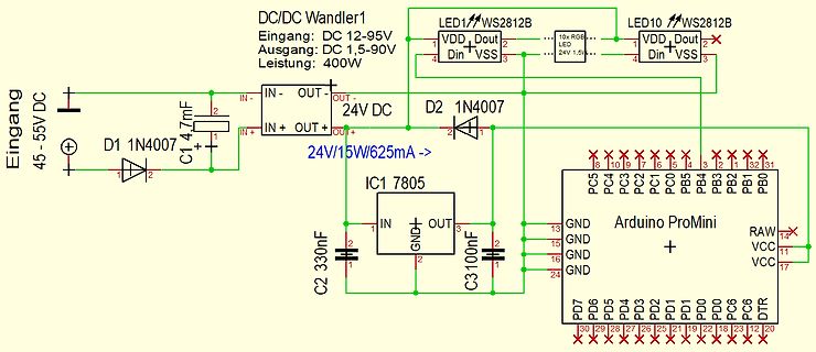
Schaltplan mit Arduino ProMini und DC/DC Wandler
DC/DC Wandler1 Eingang: DC 12-95V Ausgang: DC 1,5-90V Leistung: 400W LED1 WS2812B LED10 WS2812B VDD Dout VSS Din 24V 1,5V Eingang 45-55V DC D1 1N4007 C1 4,7mF IN- OUT- OUT+ IN+ OUT+ 24V DC D2 1N4007 IC1 7805 24V/15W/625mA -> C2 330nF C3 100nF IN GND OUT GND GND GND Arduino ProMini
-
 Bild
Bild
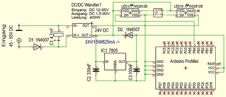
Schaltplan mit DC/DC-Wandler, Arduino ProMini und LEDs
DC/DC Wandler1 Eingang: DC 12-95V Ausgang: DC 1,5-90V Leistung: 400W LED1 WS2812B LED10 WS2812B 24V 1,5W VDD Dout Din VSS Eingang 45-55V DC D1 1N4007 C1 4,7mF IN- OUT- 24V DC IN+ OUT+ D2 1N4007 24V/15W/625mA -> IC1 7805 IN GND OUT C2 330nF C3 100nF Arduino ProMini GND GND GND RAW
-
 Bild
Bild
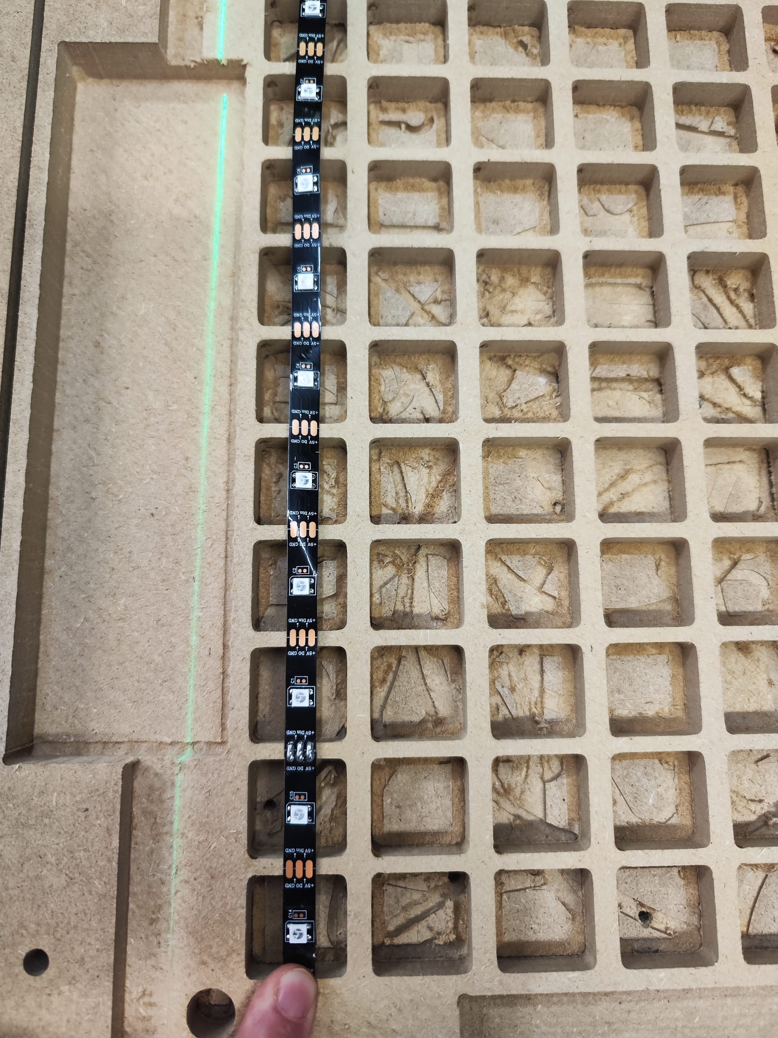
LED-Streifen auf Holzplatte
WS2812B

-
 Bild
Bild
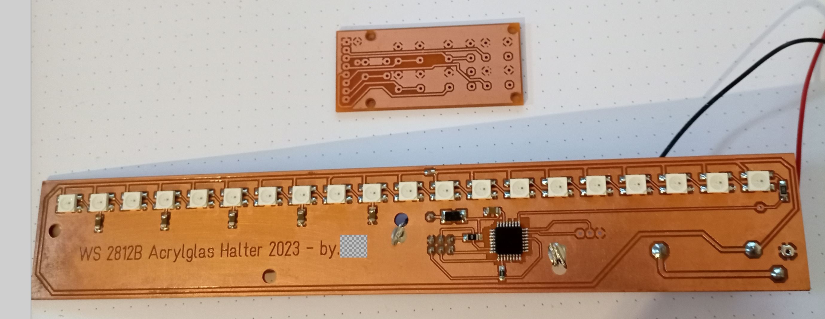
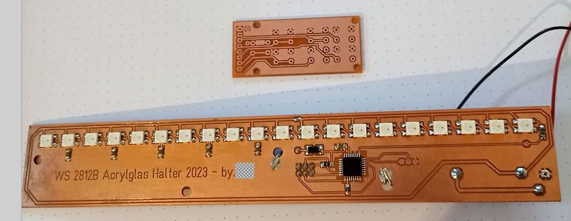
Zwei geätzte Leiterplatten mit LEDs und IC
WS 2812B Acrylglas Halter 2023 - by
-
 Bild
Bild
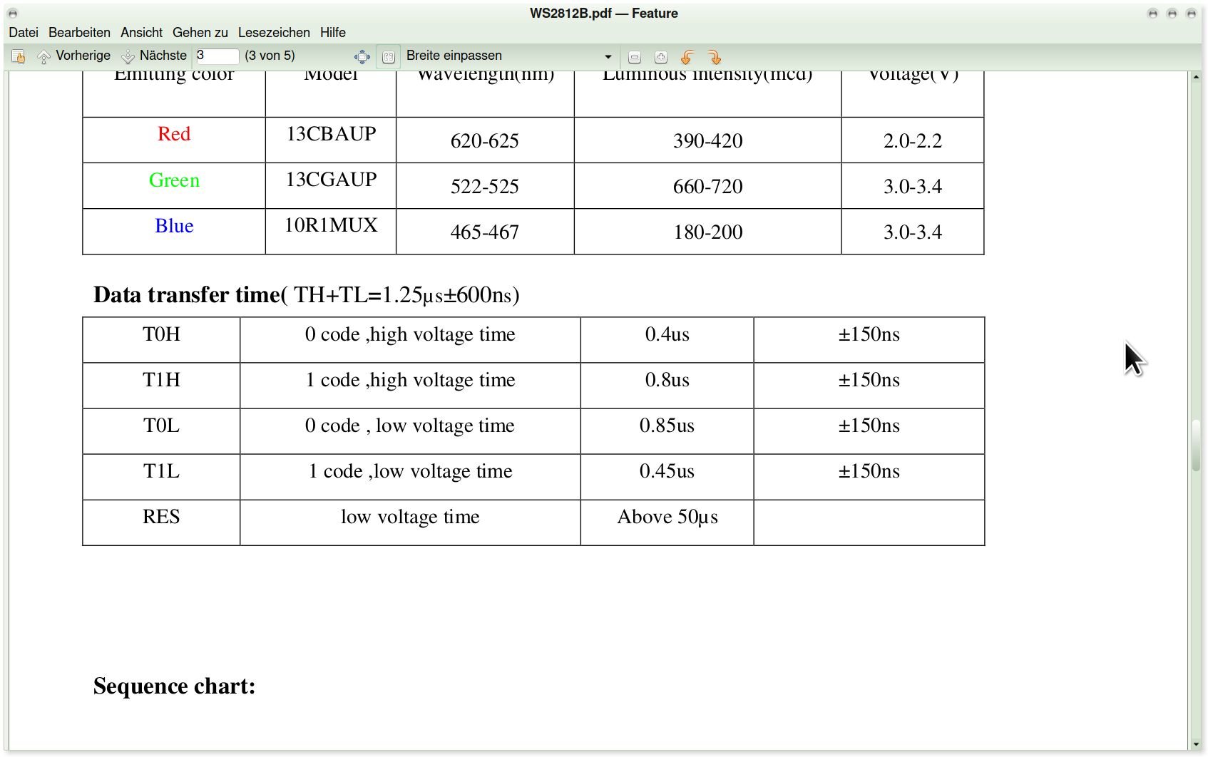
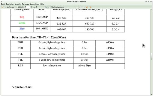
Tabelle mit technischen Daten zu Farben und Übertragungszeiten
WS2812B.pdf - Feature Red 13CBAUP 620-625 390-420 2.0-2.2 Green 13CGAUP 522-525 660-720 3.0-3.4 Blue 10R1MUX 465-467 180-200 3.0-3.4 Data transfer time( TH+TL=1.25µs±600ns) T0H 0 code, high voltage time 0.4us
-
 Bild
Bild
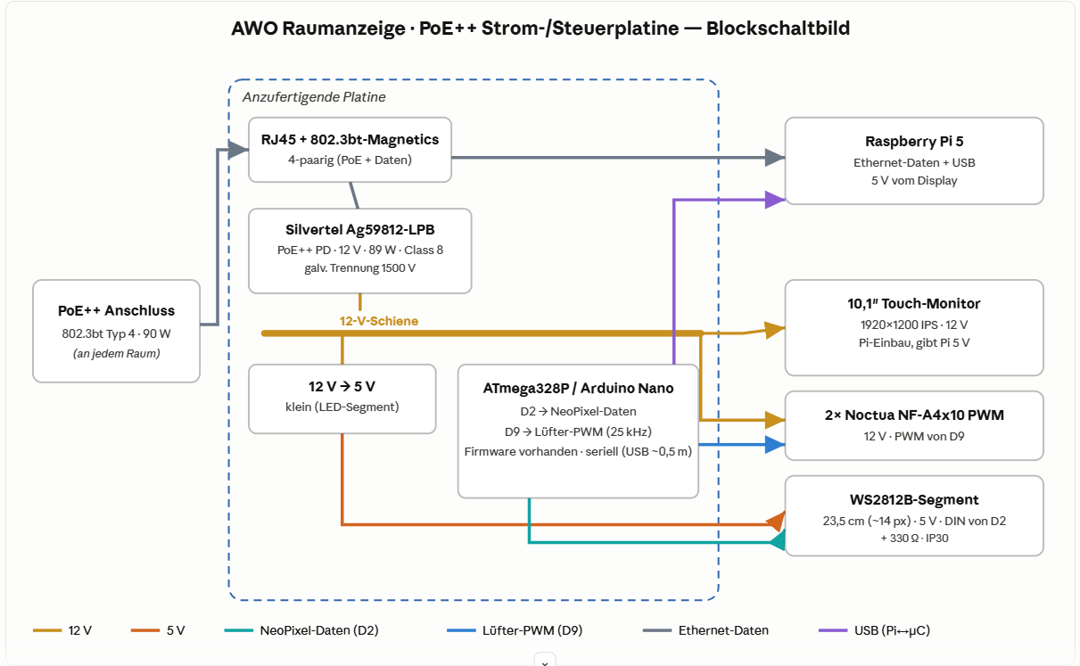
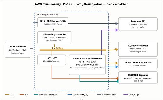
Blockschaltbild einer Strom- und Steuerplatine
Lüfter-PWM (25 kHz) Firmware vorhanden · seriell (USB ~0,5 m) 2x Noctua NF-A4x10 PWM 12 V · PWM von D9 WS2812B-Segment 23,5 cm (~14 px) · 5 V · DIN von D2 + 330 Ω · IP30 12 V 5 V NeoPixel-Daten (D2) Lüfter-PWM (D9) Ethernet-Daten USB (Pi->µC)
-
 Bild
Bild
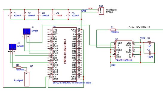
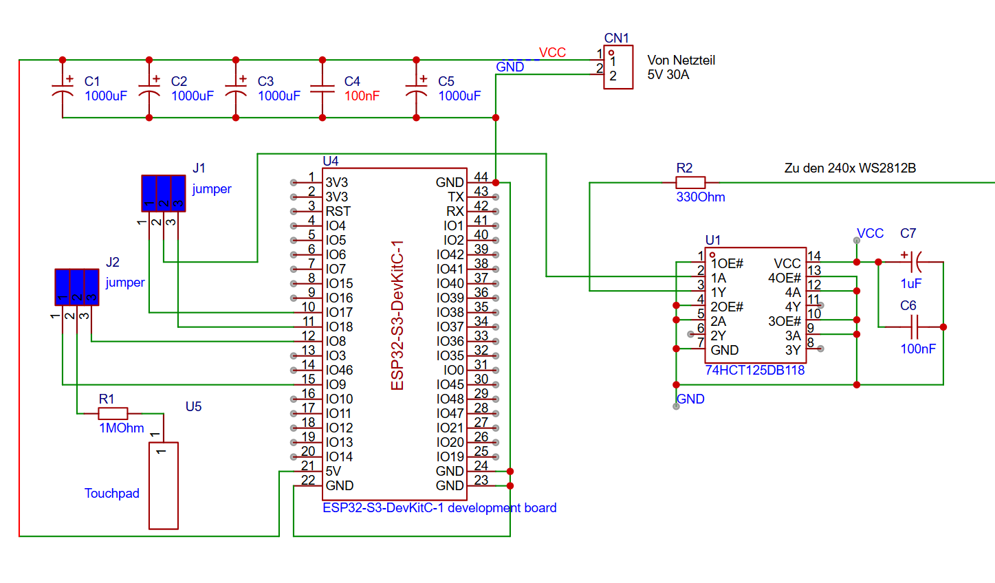
Schaltplan ESP32-S3-DevKitC-1 mit Peripherie
1000uF C3 1000uF C4 100nF C5 1000uF CN1 1 2 VCC GND 5V 30A J1 jumper J2 jumper R2 330Ohm Zu den 240x WS2812B U4 ESP32-S3-DevKitC-1 1 3V3 2 3V3 3 RST 4 IO4 5 IO5 6 IO6 7 IO7 8 IO5 9 IO6 10 IO7 11 IO8 12 IO8 13 IO4 14 IO5 15 IO9 16 IO10 17 IO11 18 IO12 19 IO13 20 IO14 21 5V 22 GND 44 GND 43 TX 42 RX 41 IO