-
 Bild
Bild
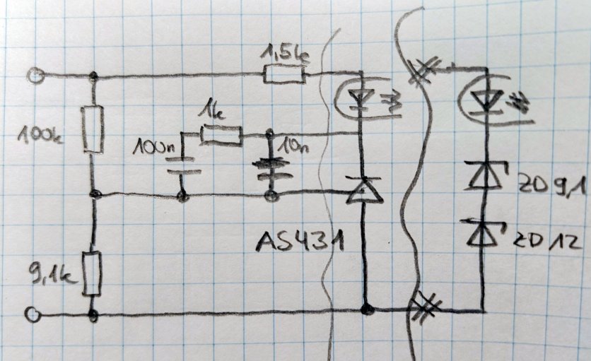
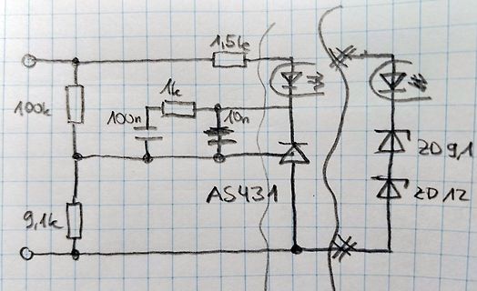
Handgezeichneter Schaltplan mit AS431
1,5k 100k 1k 100n 10n AS431 20 9,1 20 12 9,1k
-
Thread
Alterunkseffekte HCNR200
der diversen Hersteller vom Tl431 und CO, dort gibt es auch viele Beispielschaltungen.
> Es vergleicht Feedback mit solchen linearen Optokopplern mit dem > digitalen Feedback eines TL431. Schon wieder falsch. Der TL431 hat eine lineare Ansteuerung für den Optokoppler. > Ein TL431 ist ein Komparator, er macht aus der Analogspannung am Ausgang > einen eingeschalteten oder ausgeschalteten
-
Thread
Neue Bauteile: innovative Schrauben, Mikrocontroller-Thyristoren uvam
> Diotec MMTL431A-AQ – Shunt-Reglerdiode für „sehr einfache“ Spannungsregler. Ist das ein Aprilscherz oder ist die TL431 bisher an dir vorueber gegangen? :) Vanye
Vanye R. schrieb im Beitrag #8093200: >> Diotec MMTL431A-AQ – Shunt-Reglerdiode für „sehr einfache“ >> Spannungsregler. > > Ist das ein Aprilscherz oder ist die TL431 bisher an dir vorueber > gegangen? :) > Vanye Hab ich mir auch gedacht. Und auch
-
Thread
Schutzdioden BJT-Linearregler
von der TL431 und dem Spannungsteiler bestimmt, Diodes-Inc gibt etwa 0.3% max von 0-70°C für die AS431 an. Das sind 0.5 Volt bei 150 Volt.
mehr als 10µF Keramik sein, Elko im Bereich 1-100µF mit ordentlich ESR ist unkritisch. Für die TL431 Variante mit dem Kaskodetransistor Q3 ist die Regelung aber schon kompliziert. Im ersten Moment eines Lastsprungs dürfte der Q3 regeln, da die TL431 langsamer ist, dann kommt verzögert die TL431,
-
Thread
STM32G484 USB CDC Code läuft nur wenn mit <= -O1 kompiliert
Falls sich jemand mit Durchblick den Assembler Code (für den STM32G431CBT6) anschauen möchte, siehe Anhang.
entry 2 TxOffset|TxCount as one 32-bit word 8000492: str.w r4, [r1, #420] @ entry 2 RxOffset|RxCount as one 32-bit word 8000498: str.w r4, [r1, #424] @ entry 3 ... 800049e: str.w r4, [r1, #428] ``` ## Root cause
-
Thread
Neue Bauteile: Passives, Spannungsmanagement und MPUs
against dust and water. They are halogen-free and meet the requirements of EU Ecodesign 2009/125/EC as well as the RoHS Directive. Additionally, they achieve a UL 94 V-0 flammability rating. The gaskets are available in various standard profile shapes: square, as well as D, C, P, L, M, and blade profiles
above the over-voltage specification, the TW164B will switch to the next port in numerical order, as long as its power and voltage are within the expected range. The switching and port selection is, therefore, deterministic [/c] ### CUI P78B-1000 - SIP3-Schaltregler als Ersatz für LM78xx. Wer
-
Thread
Übernahmen, AI-Mikrocontroller für Automotive, Linux 6.19, Home Assistant-Alternative uvam
stattfindende Sportevent angekündigt wurde: [c] No big surprises anywhere last week, so 6.19 is out as expected – just as the US prepares to come to a complete standstill later today watching the latest batch of televised commercials. The betting man would expect them all to be AI-generated, but maybe
post-acquisition. We are confident that the acquisition will deliver exceptional value for our shareholders as we build on our strong record of financial performance as underscored by our 2025 results announced today.” [/c] ### Microchip x Hyundai zwecks Verbreitung von Single Pair Ethernet im Automobilbereich
-
Thread
STM32F552VE kann analoge Pins nicht lesen
nochmal einen Gegentest gemacht: Das prinzipiell gleiche Programm funktioniert auf einem STM32G431 Board vom selben Hersteller erfolgreich.
ADC_PCSEL register. Note: Configuring the PCSEL bit is not necessary for the internal channels (such as VREFINT).[/pre]
-
Thread
Picoamperemeter Elektor
DG412DJN, DIL IC4 = ADS1113, Adapter-PCB SMD auf DIL IC5 = DAC8830, Adapter-PCB SMD auf DIL IC6 = TL431C, TO-92 Q1, Q2 = 2N7000, n-kanaliger MOSFET D1, D2 = BAT42, THT IC1 = LM337, TO-92 IC2 = LM317, TO-92 ESP32 = NodeMCU ESP32, WiFi und Bluetooth M1 = MT3608, DC/DC-Step-up-Wandler
vom AATIS sehr zufrieden. Und der Preis passt ins Hobbybudget. https://www.aatis.de/content/bausatz/AS608_pA-Messverst%C3%A4rker
-
Thread
24-Kanal PWM Led-Controller mit key-scan
Mit STM32G431R6T im LQFP-64 geht es praktisch ±0 auf. Der hat Hardware für 25 PWM-Kanäle mit 16 Bit Auflösung bei max. 2600 Hz. Die restlichen Pins reichen für 7 bis 10 ADC-Eingänge für die Tastenmatrix, zwei 12-
> Normaldenkender aus dem Thread hätte lernen können. danke fürs erneut beleidigen. MAX7370,AS1115, der bereits genannte HT16k33 in unzähligen Varianten von verschiedenen Herstellern, STLED316S...alle ähnlich, alle nicht ganz, was ich suche. aber gut.
-
Thread
Günstiges und einfaches Mini-Controller Board, was würdet ihr heute nehmen?
Selbstmachen beschrieben: https://mcuoneclipse.com/2022/09/17/picoprobe-using-the-raspberry-pi-pico-as-debug-probe/
mal etwas Konkretes vorzuschlagen: https://www.mouser.de/ProductDetail/STMicroelectronics/NUCLEO-G431RB?qs=T3oQrply3y%252BHSoH%2FYfQbYw%3D%3D
-
Thread
Unbekannte Bauteile in Gate-Ansteuerung Schaltnetzteil
erstes und zweites Bild. Wenn ich das richtig interpretiere, handelt es sich um eine Spannungsreferenz "AS431" im SOT-23-Gehäuse. Wenn ich mich nicht verrechnet habe, sollten sich da da 29 Volt (1+100/9,1)*2,500V als "Fußpunkt" für den Optokoppler an der "Anode" einstellen, kommt mir recht viel vor. Tatsächlich
-
Thread
Fehlersuche Konstanstromquelle LM317LZ
sorgfältig gelesen. Ja, der LM334 hat eine definierte Temperaturabhängigkeit, aber auf Seite 8 "Application as a Zero Temperature Coefficent Current Source" zeigt TI den Umgang damit. Bedenken kann man anmelden, wie es mit einer anderen Diode läuft: "The recommended diode for use in this circuit is the 1N457
Temperaturkoeffizient des Stroms pro Grad muss also kleiner als 0.01% (100 ppm) sein. Das ist mit einer TL431 (typisch 50 ppm) und einem 50 ppm Widerstand zum Einstellen des Stroms gerade noch machbar. Ein LM317L dürfte das an guten Tagen schaffen, das Problem ist der Adjustment Strom, die 1.24 Volt Referenz
-
Thread
avr adc streuung ausgleichen
The AVCC pin on the device should be connected to the digital VCC supply voltage via an LC network as shown in Figure 23-9 on page 213. Es ist ja jedem selbst überlassen ob er den Filter einbaut oder nicht. Ein AVR wird auch ohne Abblockkondensator zw. VCC und GND laufen, trotzdem baue ich den ein
Signifikantes am angezeigten Ergebnis ändern würde) ``` ADC faktor 127 7388797 In: 14.319 V … 14.431 V Mess: 14319.000 mV … 14431.000 mV 255 7374343 In: 28.694 V … 28.806 V Mess: 28694.000 mV … 28806.000 mV 511 7367157 In: 57.444 V … 57.556 V Mess: 57444.000 mV … 57556.000 mV 767 7364769
-
 Bild
Bild
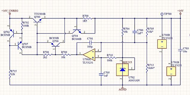
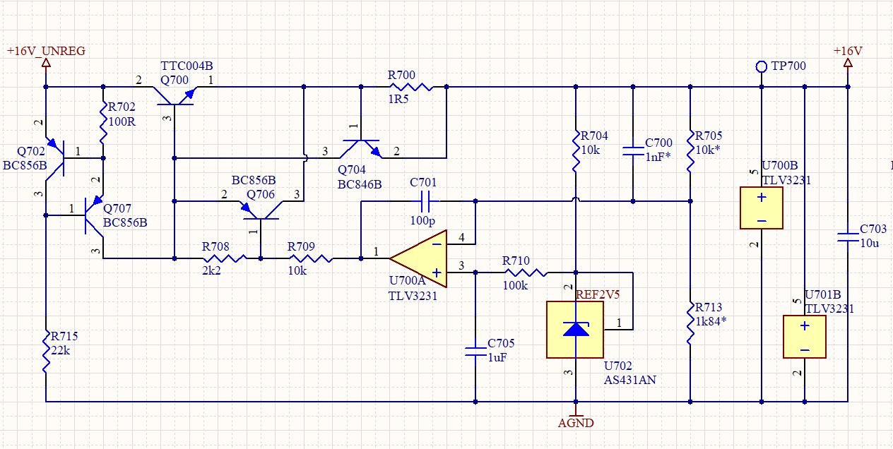
Schaltplan einer Spannungsreferenzschaltung
BC56B,3,1,R715,22k,3,R708,2k2,2,Q706,BC856B,3,R709,10k,4,U700A,TLV3231,100p,3,R710,100k,REF2V5,1,U702,AS431AN,3,AGND,C705,1uF,R704,10k,C700,1nF*,R705,10k*,1,R5,1R5,TP700,+16V,5,U700B,TLV3231,+,2,C703,10u,5,U701B,TLV3231,+,2