-
Bild
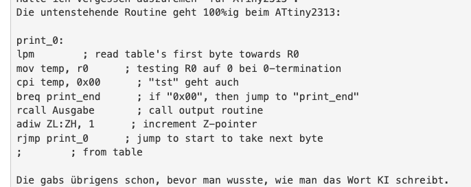
Assembler-Code für ATtiny2313
print_0: lpm ; read table's first byte towards R0 mov temp, r0 ; testing R0 auf 0 bei 0-termination cpi temp, 0x00 ; "tst" geht auch breq print_end ; if "0x00", then jump to "print_end" rcall Ausgabe ; call output routine adiw ZL:ZH, 1 ; increment Z-pointer rjmp print_0 ; jump to start to take next byte
in „I2C Display einfache Frage“ · Mikrocontroller und Digitale Elektronik · · Screenshots
-
Bild
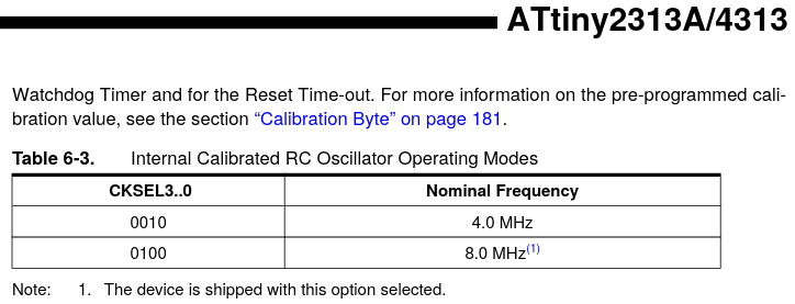
Tabellenausschnitt aus einem ATtiny2313A/4313 Datenblatt
ATtiny2313A/4313 Watchdog Timer and for the Reset Time-out. For more information on the pre-programmed calibration value, see the section "Calibration Byte" on page 181. Table 6-3. Internal Calibrated RC
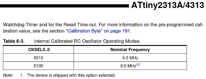
in „ATTiny 2313-20PU und 2313A-PU“ · Mikrocontroller und Digitale Elektronik · · Screenshots
-
Bild
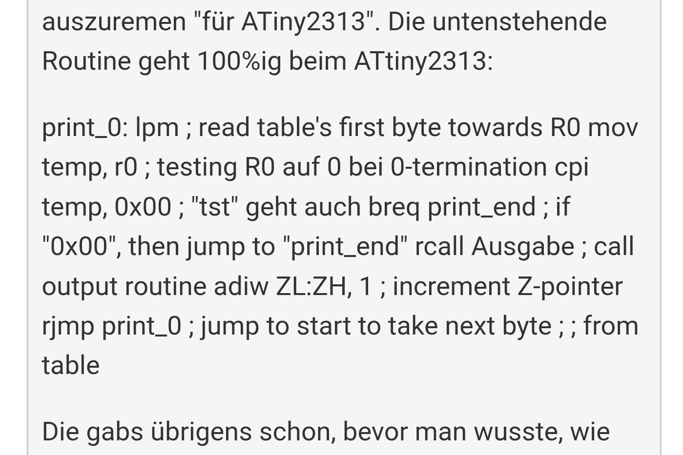
Text mit Assembler-Code für ATtiny2313
auszuremen "für ATtiny2313". Die untenstehende Routine geht 100%ig beim ATtiny2313: print_0: lpm ; read table's first byte towards R0 mov temp, r0 ; testing R0 auf 0 bei 0-termination cpi temp, 0x00 ; "tst" geht auch breq
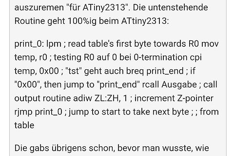
in „I2C Display einfache Frage“ · Mikrocontroller und Digitale Elektronik · · Screenshots
-
Bild
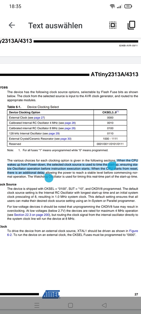
Ausschnitt aus einem Datenblatt eines ATtiny2313A Mikrocontrollers
ATtiny2313A/4313 Table 6-1. Device Clock Select Device Clocking Option | CKSEL3..0 External Clock | 0000 Calibrated Internal RC Oscillator 4 MHz | 0010 Calibrated Internal RC Oscillator 8 MHz | 0100 128 kHz
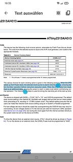
in „ATTiny 2313-20PU und 2313A-PU“ · Mikrocontroller und Digitale Elektronik · · Screenshots
-
Bild
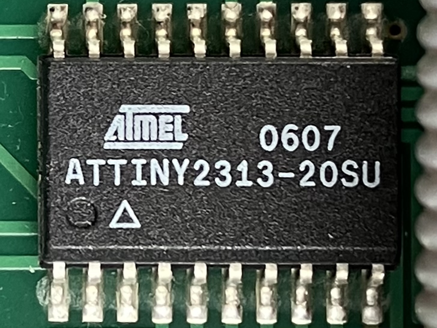
Atmel ATtiny2313-20SU Mikrocontroller auf Leiterplatte
ATMEL 0607 ATTINY2313-20SU
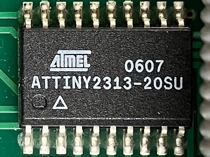
in „Hameg 8040-3 HF-Störungen“ · Analoge Elektronik und Schaltungstechnik · · Platinenfotos
-
Datei
SainSmart2004_ATtiny2313.asm
;*************************************************** ; Test TWI via USI-Interface ; MCU: ATMEL ATtiny2313 ; Clock: 4 MHz ; TWI/I2C-PortB PB7=SCL; PB5=SDA ; LCD: 4x20 SainSmart2004; HD44780 compatible ; P7 P6 P5 P4 P3 P2 P1 P0 ; D7 D6 D5 D4 LED ENA R|W RS ; ;ATtiny2313 memory use summary [bytes]: ;Segment
in „I2C Display einfache Frage“ · Mikrocontroller und Digitale Elektronik ·
-
Datei
OLED_Test2_Attiny2313.asm
************************************************* ; OLED Test I2C via USI-Interface ; MCU: ATMEL ATtiny2313 (ATtiny4313) ; Clock: 4 MHz ; I2C-PortB PB7=SCL; PB5=SDA ; ; Device slave address: $3C OLED ;ATtiny4313 memory use summary [bytes]: ;Segment Begin End Code Data Used Size Use% ;[cseg] 0x000000
in „I2C Display einfache Frage“ · Mikrocontroller und Digitale Elektronik ·
-
Datei
uart_and_lcd.c
werden kann, welche Toolchain zum Uebersetzen verwendet wird. MCU : ATmega8, ATmega48/88/168/328p, ATtiny2313/4313 Takt: 16 MHz 30.05.2026 R. Seelig ----------------------------------------------- */ #include <avr/io.h> #include <util/delay.h> #include <stdint.h> /* ------------------------------------
in „Kommunikation zwischen 2 MC“ · Mikrocontroller und Digitale Elektronik ·
-
Bild
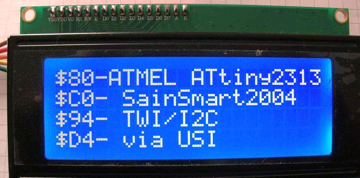
LCD-Display mit Textanzeige und Anschlussleiste
$80- ATTMEL ATTiny2313 $C0- SainSmart2004 $94- TWI/I2C $D4- via USI VSS VDD VO RS RW E D0 D1 D2 D3 D4 D5 D6 D7 A K
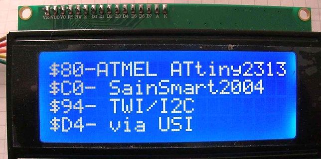
in „HD44780 I2C Adapter“ · Mikrocontroller und Digitale Elektronik · · Fotos
-
Datei
LCD_I2C_01.asm
;*************************************************** ; Test TWI via USI-Interface ; MCU: ATMEL ATtiny4313 ; Clock: 4 MHz ; TWI/I2C-PortB PB7=SCL; PB5=SDA ; LCD: 4x20 SainSmart2004; HD44780 compatible ; P7 P6 P5 P4 P3 P2 P1 P0 ; D7 D6 D5 D4 LED ENA R|W RS ; Device slave address: $38 (PCF8574A) ;ATtiny2313
in „I2C Display einfache Frage“ · Mikrocontroller und Digitale Elektronik ·
-
Datei
DCF77_Connection.asm
- - - - ;ATtiny4313 memory use summary [bytes]: ;Segment Begin End Code Data Used Size Use% ;[.cseg] 0x000000 0x0001fc 496 12 508 4096 12.4% ;[.dseg] 0x000060 0x000060 0 0 0 256 0.0% ;[.eseg] 0x000000 0x000000 0 0
-
Datei
oled_2313demo.c
/* ----------------------------------------------------- oled_2313demo.c Minimalprogramm fuer Textausgabe auf einem OLED-Display mit SSD1306 oder SSD1315 Display, explizit fuer einen ATtiny2313 Mikrocontroller MCU : ATtiny2313 Takt : 8 MHz Fuses : Low: 0xe4 | High:
in „I2C Display einfache Frage“ · Mikrocontroller und Digitale Elektronik ·
-
Bild
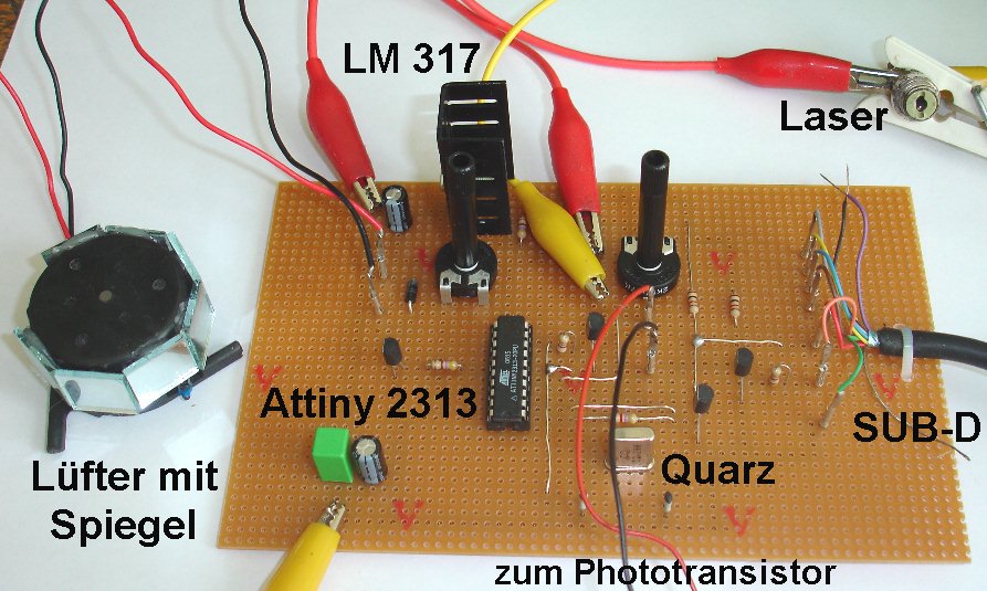
Aufbau einer Elektronikschaltung auf Lochrasterplatine
LM 317 Laser Lüfter mit Spiegel Attiny 2313 Quarz SUB-D zum Phototransistor
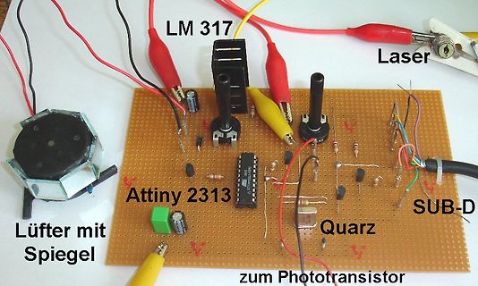
in „Physikprojekte“ · Offtopic · · Platinenfotos
-
Bild
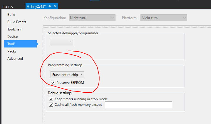
Software-Einstellungen für Mikrocontroller-Programmierung
main.c ATTiny2313* Build Konfiguration: Nicht zutr. Plattform: Nicht zutr. Toolchain Device Tool* Packs Advanced Selected debugger/programmer Programming settings Erase entire chip Preserve EEPROM Debug settings
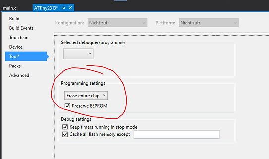
in „Probleme mit studio4“ · Mikrocontroller und Digitale Elektronik · · Screenshots
-
Datei
SainSmart_USI_27022026.asm
;*************************************************** ; Test TWI via USI-Interface ; MCU: ATMEL ATtiny4313 ; Clock: 4 MHz ; TWI/I2C-PortB PB7=SCL; PB5=SDA ; LCD: 4x20 SainSmart2004; HD44780 compatible ; P7 P6 P5 P4 P3 P2 P1 P0 ; D7 D6 D5 D4 LED ENA R|W RS ; Device slave address: $38 (PCF8574A) ;ATtiny4313
in „HD44780 I2C Adapter“ · Mikrocontroller und Digitale Elektronik ·
-
Datei
A_I2C_Test.asm
;*************************************************** ; Test TWI via USI-Interface ; MCU: ATMEL ATtiny4313 ; Clock: 4 MHz ; TWI/I2C-PortB PB7=SCL; PB5=SDA ; OLED ; P7 P6 P5 P4 P3 P2 P1 P0 ; ; Device slave address: $3C ; ; Rev.: 25022026 ;*************************************************** ; ;Assembler
in „I2C Display einfache Frage“ · Mikrocontroller und Digitale Elektronik ·
-
Datei
Oled_init_05.asm
************************************************* ; OLED Test I2C via USI-Interface ; MCU: ATMEL ATtiny4313 ; Clock: 4 MHz (resp. STK500 clock) ; I2C-PortB PB7=SCL; PB5=SDA ; ; Device slave address: $3C OLED => 0x78 ;ATtiny4313 memory use summary [bytes]: ;Segment Begin End Code Data Used Size Use% ;
in „I2C Display einfache Frage“ · Mikrocontroller und Digitale Elektronik ·