-
 Bild
Bild
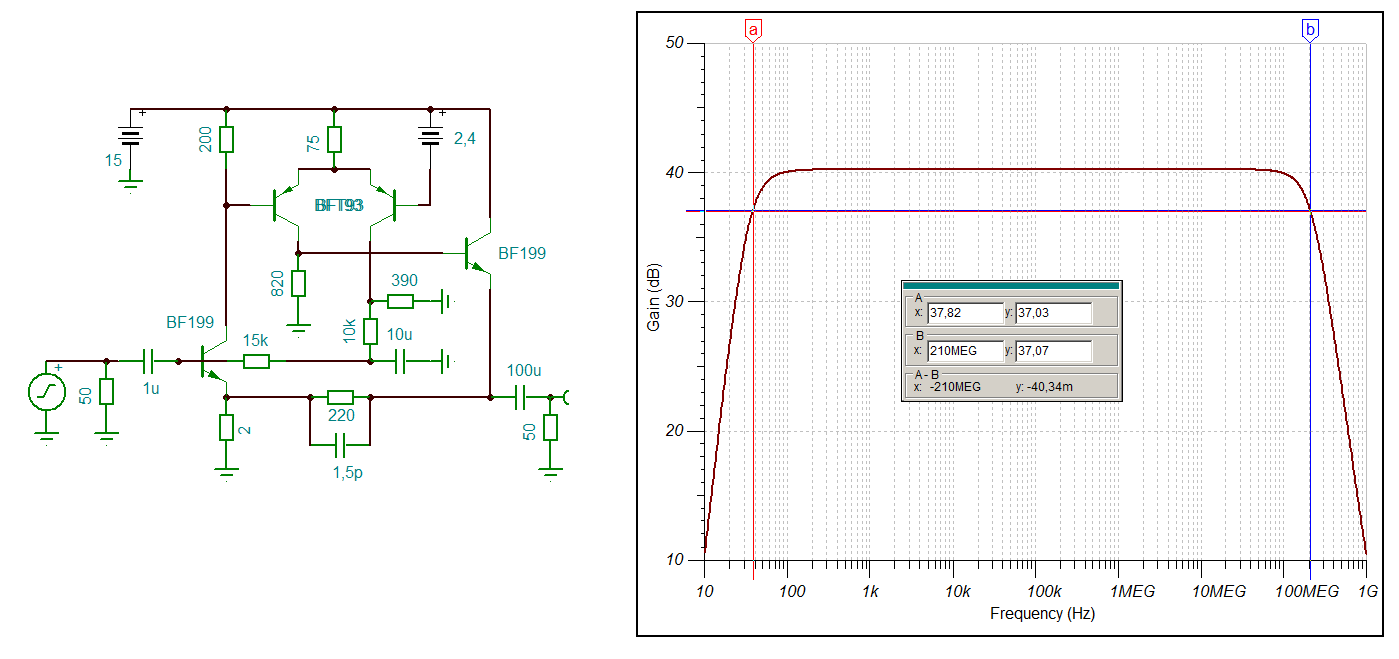
Schaltplan und Frequenzgang-Diagramm eines Verstärkers
15 200 75 2,4 BFT93 BF199 820 390 15k 10k 10u BF199 1u 50 2 220 1,5p 100u 50 Gain (dB) a b x 37,82 y 37,03 B x 210MEG y 37,07 A - B x -210MEG y -40,34 Frequency (Hz) 10 100 1k 10k 100k 1MEG 10MEG 100MEG 1G
in „HP461 - Verstärker 20/40dB“ · HF, Funk und Felder · · Screenshots
-
Datei
utf8_demo.c
-164 0xC3,0x91,0x00, // ASCII-165 0xC2,0xAA,0x00, // ASCII-166 0xC2,0xBA,0x00, // ASCII-167 0xC2,0xBF,0x00, // ASCII-168 0xE2,0x8C,0x90, // ASCII-169 0xC2,0xAC,0x00, // ASCII-170 0xC2,0xBD,0x00, // ASCII-171 0xC2,0xBC,0x00, // ASCII-172 0xC2,0xA1,0x00, // ASCII-173 0xC2,0xAB,0x00, // ASCII-174 0xC2,0xBB
in „Cursorpositionierung, Farben und Codepage 437 Ausgabe im Linuxterminakl“ · Projekte & Code ·
-
Datei
disassebled_minimal_change_crash.asm
01 movw r24, r28 be8: 09 95 icall bea: 0c 89 ldd r16, Y+20 ; 0x14 bec: 10 e0 ldi r17, 0x00 ; 0 bee: bf b6 in r11, 0x3f ; 63 bf0: f8 94 cli bf2: 60 e0 ldi r22, 0x00 ; 0 bf4: 70 e2 ldi r23, 0x20 ; 32 bf6: 81 ea ldi r24, 0xA1 ; 161 bf8: 97 e0 ldi r25, 0x07 ; 7 bfa: a7 01 movw r20, r14 bfc: 96 01 movw r18
in „Bizarrer Firmware crash - ATmega4808. Wie Debuggen?“ · Mikrocontroller und Digitale Elektronik ·
-
Datei
disassebled_original_working.asm
01 movw r24, r28 be8: 09 95 icall bea: 0c 89 ldd r16, Y+20 ; 0x14 bec: 10 e0 ldi r17, 0x00 ; 0 bee: bf b6 in r11, 0x3f ; 63 bf0: f8 94 cli bf2: 60 e0 ldi r22, 0x00 ; 0 bf4: 70 e2 ldi r23, 0x20 ; 32 bf6: 81 ea ldi r24, 0xA1 ; 161 bf8: 97 e0 ldi r25, 0x07 ; 7 bfa: a7 01 movw r20, r14 bfc: 96 01 movw r18
in „Bizarrer Firmware crash - ATmega4808. Wie Debuggen?“ · Mikrocontroller und Digitale Elektronik ·
-
PDF
TM56M152A-tenxtechnology.pdf
as “RAM Bank1 area (32 Bytes)” in the table of memory map. 0.87 Oct, 2023 4. Change “A0~EF” as “A0~BF” in the table of memory map. 5. Update Min Operating Voltage in Characteristics Graphs 6. change device type as TM56M152A 7.Add ordering number for sop14 8. Change maximum voltage as 5.2V for “ADC reference
in „MCU identifikation/Datenblatt - MC9989A0ZQ“ · Mikrocontroller und Digitale Elektronik ·
-
PDF
T6963C.pdf
······ 0097 008C 008D ········· 009F 00A0 ········· 00AB 00A0 00A1 ········· 00B3 00B4 ········· 00BF 00B4 00B5 ········· 00C7 00C8 ········· 00D3 00C8 00C9 ········· 00DB 00DC ········· 00E7 00DC 00DD ········· 00EF 00F0 ········· 00FD 00F0 00F1 ········· 0103 0104 ········· 011F 0104 0105 ·········
in „altes Phytec MCB-51 Monitor/Basic Befehle?“ · Mikrocontroller und Digitale Elektronik ·
-
PDF
MS-17631_2.0.pdf
CKE0 6 DQ26 67 M_A_DQ26 +3VRUN 124 VDD VSS 145 <5,9> M_A_CAS# 115 CAS# DQ28 56 M_A_DQ29 S C500 C497 199 VDDSPD VSS 151 JNC301 2 X_0402 <<5,9> M_A_WE# SA0_DIM0_0 197 WE## DQ30 70 M_A_DQ31 C C0.1u10X0402 X_C2.2u6.3X0603 125 NC2 VSS 161 JNC311 2 X_0402 SA1_DIM0_0 202 SA1 DQ32 131 M_A_DQ33 TPJNC45JNC 198
in „In Circuit Programmierer für 8-pin 150mil SOIC PM25LD512“ · Mikrocontroller und Digitale Elektronik ·
-
PDF
TM56E6422-tenxtechnology.pdf
196h 017h ADCDH 097h PWM1DL 117h 197h 018h ADCTL 098h PWM2DH 118h 198h 019h ADCTL2 099h PWM2DL 119h 199h 01Ah 09Ah PWM3DH 11Ah 19Ah 01Bh 09Bh PWM3DL 11Bh 19Bh 01Ch 09Ch PWM4DH 11Ch 19Ch 01Dh 09Dh PWM4DL 11Dh 19Dh 01Eh 09Eh PWM5DH 11Eh 19Eh 01Fh 09Fh PWM5DL 11Fh 19Fh 020h 0A0h 120h 1A0h RAM Bank0 area
in „MCU identifikation/Datenblatt - MC9989A0ZQ“ · Mikrocontroller und Digitale Elektronik ·
-
PDF
rudi_____RX-V4A_TSR-400.pdf
3 4 9 +3.7WN C 8ch digital sample rate converter サービス部品供給なし @pinNa - 5 I 1 2 1 0 D 2 M E R CE +3.3BF 0 9 EPSON 0 8 10KX4 F F F M M S D S S T U T T H 3 2 GND 7 6 / 7 K R9667 D D D E E N V S M M M M I 4 R R9672 I . 9 0 I I I D D I D V S S S S D +3.3V_PU +3.3BF 1M T 0 R 1 J9664 / +3.3SRC K K K 3 4 1 2
in „Test in der Schaltung STR3A400“ · Analoge Elektronik und Schaltungstechnik ·
-
PDF
technical.pdf
198 12.11Microstrip via hole . . . . . . . . . . . . . . . . . . . . . . . . . . . . . . . . . . . . 199 12.12Bondwire . . . . . . . . . . . . . . . . . . . . . . . . . . . . . . . . . . . . . . . . . 200 12.12.1Freespace model . . . . . . . . . . . . . . . . . . . . . . . . . . . . . . . . . 201 12.12.2Mirror
-
PDF
53131a_53132a_bedienungsanleitung_deutsch_komprimiert.pdf
Zeit>> ZZEIT: <Zeit> **Für Spaanunungsspitzen- essungen isistkein Menü Gateate& ExtArm verfügbar.. 2-199 Bedienung de Universalzahlers Die Menüttaste G t & ExtArm Verwendungung v on G ate nd E xternalIAr m or xterne rne Trriggersp rre V efahrer n ü To &r exter e Trigg r pe re (Be s i I)l) Z Denimonsttrationszweckenist
in „[V] HP/Agilent 53131a/53132a Bedienungsanleitung deutsch“ · Markt ·