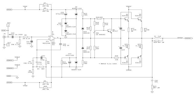
dieses NOS-Angebot gestolpert: https://www.ebay.de/itm/365416088019 "20 Stück neuer Transistor BD142", 19,68 EUR. Kennt jemand den Hersteller? Das Logo "Ei" kenne ich nicht. Datenblatt finde ich nur eines von "Comset", einem mir ebenfalls unbekannten Hersteller. Was meinen die Bauteil-Experten
recht günstiges > Angebot. BD130 ist andere Bezeichnung für 2N3055, kann z.B. mehr UCE. Beim BD142 ist bei 45V Schluss. Ob der als direkter Ersatz geeignet ist, hängt von den Schaltungsanforderungen ab. ciao gustav
tatsächlich, das diese nun die Datenrate des W-Lan drückt. Man kann die Uhr noch 1 Etage höher auf u.a. 142.410 MHz höhren. Das soll so nicht länger sein.
Unterschiede, die man den Dingern ja nicht ansieht. Da forsche ich noch, oder hat jemand einen guten Geräte Tip? Ansonsten, 5V Trafonetzteil bauen.
Pin 16) 0 – –10 mA Sync, Blanking Level (DC level between pulses, see Figure 9e) 1.7 – 8.2 Vdc Sync Tip Level (see Figure 9e) –0.5 0 0.9 Sync Pulse Width (see Figure 9e) 2.5 – 5.2 s R, G, B Input (Amplitude) – 1.0 – V pp R, G, B Peak Levels for DC Coupled Inputs, with Respect to Ground 2.2 – 4.4 V Chrominance
HOLTITESOCKETPRINTEDWIRINGCONTACTKIT HOLTITESOCKETTIPS a PartNumber398-HK-001(GoldHOLTITESockets)and Tip#399-HT-112isforusewith5PHOLTITESocketsandisbluein A a 398-HK-002(Tin/LeadHOLTITESockets) color. o This“starter"”kitisprimarilydesignedtoallowtheloadingofHOLTITETip#399-HT-113isforusewith6P,8P,&12PHOLTITESocketsandis
bolts (see items 1 and 2 in fig. 2.3 - 2). If you do not do this, the com- ponent feeder table could tip over and the placement head could collide with the feeder as it ap- proaches the feeder area. 2 30 Service Manual S-27 HM 2 Operational safety 10/2005 US Issue 2.3 Laser classification Fig. 2.3 - 2
! • To remove the Wireless LAN Antenna Connector, use the special MHF Connector Remover. Hook the tip of this tool on the cover of the Wireless LAN Antenna Connector and pull it straight in the direction of the engaging axis of the Wireless LAN Black Antenna Connector. ࠇ Special removing tool CABLE
S T ROUTINE J U S T air . Fig. 22. Flow-chart display output routine 3 3 : 1.4.2. Analogsection | 142..D ret olageeasuemens( V.) | i l The input circuit for the d.c. voltage measurements isshown in Fig. 23. The various ranges are selected by reed relay switches, which connect resist:rs in parallel with

 Bild
Bild
 Bild
Bild
 Bild
Bild