16-bit Registers” on page 109. The Timer/Counter Control Registers (TCCRnA/B/C) are 8-bit registers and have no CPU access restrictions. Interrupt requests (shorten as Int.Req.) signals are all visible in the Timer Interrupt Flag
typisch in Dropbox: https://www.dropbox.com/sh/epucei8lmoz7xpp/AAAmon04b1DiSOeh1q4nAhzAa?e=1&spm=a2g0o.detail.1000023.1.676claGNlaGNb1&dl=0 https://www.dropbox.com/sh/pznvlzx8qx5nfr3/AABpzhSyjqH0qWNYgMvxqAA9a?e=1&spm=a2g0s.imconversation.0.0.109b3e5fckU9p0&dl=0 Auch in den Sourcecodes von Grow
schrieb im Beitrag #7607929: > two pixels are combined into one > byte. (The high four bits are a pixel, the low four bits are a pixel in > the next adjacent column of the same > row Beim Lesen ist mir aufgefallen, dass Du im Eröffnungsposting geschrieben hast, in einem Byte wären zwei Pixel
auf 5V liegt (oder was auch immer da ankommt). Der ACS712 hat 2.5V ohne zu messenden Strom und 66mA beim 30A-Type, 100mA beim 20A-Type und 184mA beim 5A-Type. Beim 30A-Type machen 2A 27 Schritte aus, was sicher genau genug zu messen ist, wenn man zwischen 20A und 30A messen will. Der 20A-Type,
von 2,5V + Imess * 100mV/A = 2,5V + 5A * 100mV/A = 2,5V + 500mV = 3V ausgeben. > Beim 30A-Type machen 2A 27 Schritte aus, was sicher genau genug zu > messen ist, wenn man zwischen 20A und 30A messen will. 1 Schritt des
The converted value is padded on the right with blanks, rather than on the left with blanks or zeros A blank should be left before a positive number (or empty string) ' ' (a space) produced by a signed conversion A sign (+ or -) should always be placed before a number produced by a + signed conversion
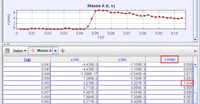
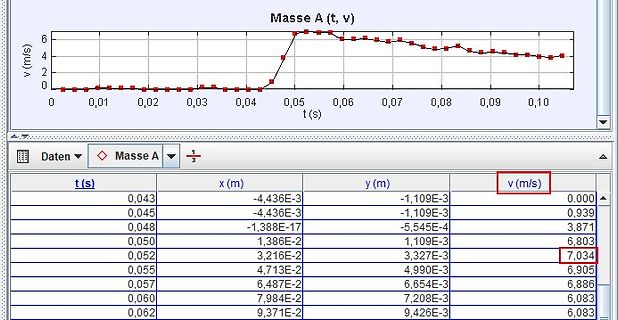
Masse A (t, v)
v (m/s)
t (s)
Daten
Masse A
t (s)
x (m)
y (m)
v (m/s)
0,043 -4,436E-3 -1,109E-3 0,000
0,045 -4,436E-3 -1,109E-3 0,939
0,048 -1,388E-17 -5,545E-4 3,871
0,050 1,386E-2 1,109E-3 6,803
0,052 3,216E
waren und nicht gleich zerstört wurden. Bei der "Germanisierung" der Mig-29 in den 90igern musste u.a. ein westliches Anti-Collision-Light nachgerüstet werden, dessen Impulse aber massiv die Bussysteme der interne Waffenanlage störte. Man bekam das mit zusätzlichen Abschirmungen hin. Generell wird
(prx) A. K. schrieb im Beitrag #7596689: > Nicht mehr. Waren früher nur Teile wie das Seitenleitwerk auf CFK, sind > es nun auch Rümpfe und Flügel. Und du meinst, CFK wäre ein Isolator?
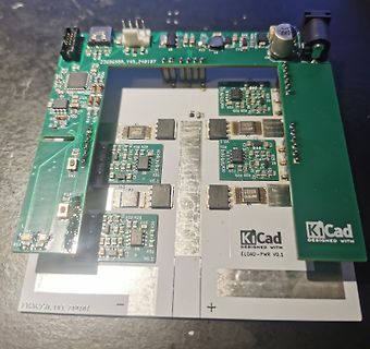
: > Welcher der auf dem Foto gezeigten USB-C Breakout Boards > funktioniert zuverlässig für 5V 3A? Besorge die technischen Daten dazu. Am Foto kann man das nicht erkennen. Was zum Lesen dazu: https://www.ti.com/lit/wp/slyy109b/slyy109b.pdf
Daten dazu. Am Foto kann man das nicht erkennen. > Was zum Lesen dazu: https://www.ti.com/lit/wp/slyy109b/slyy109b.pdf Super, da steht es auch so geschrieben, wie ich es vermutet habe: Without USB PD, you can support up to 5 V at 3 A (15 W) with just USB Type-C alone. Das gilt für USB PD 3.0 Charger
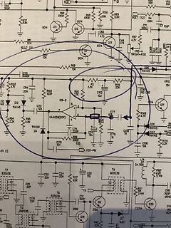
Hallo Zusammen, folgende Situation: Ein PIC32MM0128GPM048 auf Board A, hat zu wenige 24V-Ausgänge, weshalb ich mit einem 74HC595 auf Board B 16 weitere 24V-Ausgänge schaffen möchte. Ausgangsschaltung auf Board A siehe „24V-Ausgang_Board_A“. Hier ist im 24V-Ausgang gleichzeitig
Felix schrieb im Beitrag #7590856: > Ein PIC32MM0128GPM048 auf Board A, hat zu wenige 24V-Ausgänge Hmm, wenn T109 nur -20V Gate-Spannung aushält, an orange aber 24V anliegen, killt C309 den T109. Wer auch immer den Murks verzapft hat. Felix schrieb im Beitrag #7590856
M O D U L A R I N S T R U M E N T A T I O N FE-560-IA Isolation Amplifier The FE-560-IA is an Isolation Amplifier in the FYLDE "blue panel" modular range of signal conditioning, and is a general purpose isolation
6,17/19 SOS4_PS TO 12,17/19 SOS4_PS 1 2 C S C C S D _ _ _ _ H _ 4 6 7 8 U O O O O O C S S S S S S 2 109 110 111 112 113 114 115 116 117 59 13.18. A-Board (14/19) Schematic Diagram ! A-BOARD (14/19) PD4H PD4H P_S0 *IC9300 U3 DCCOP40 *IC9300 V30 XI P_S1 *IC9300 P3 DCCOP41 C9301 IC9300 50V 6 15p C1AB00003259
Frequency 50-60 Hz 50-60 Hz Operating Line Frequency Range 47-63 Hz 47-63 Hz Rated Input Current 8A/4A 6A/3A Heat Dissipation 1575 BTU/hr maximum 315BTU/hr typical 1260 BTU/hr maximum 315 BTU/hr typical Power Supply Fan Variable speed fan Variable speed fan Energy Star Compliant YES YES FEMP Standby
Frequency 50-60 Hz 50-60 Hz Operating Line Frequency Range 47-63 Hz 47-63 Hz Rated Input Current 8A/4A 6A/3A Heat Dissipation 1575 BTU/hr maximum 315BTU/hr typical 1260 BTU/hr maximum 315 BTU/hr typical Power Supply Fan Variable speed fan Variable speed fan Energy Star Compliant YES YES FEMP Standby
Hat der nicht einen Slot für den Printserver z.B. den SEH IC-109 den es oft für wenige Euronen in der Bucht gibt? mfG Michael
Ich hatte den FS1700 da gab es von SEH eine Netwerkkarte SEH IC-109 zum einbauen vielleicht gibt es sowas noch für kleiner 10€ +Porto. Naja 26€ inklusive Versand: https://dasdruckerteam.de/kyocera-seh-ic-109-netzwerkkarte SEH aus Bielefeld gibt es auch noch seit
Ansonsten > bricht die Ausgangsspannung halt ein. Danke, wieder etwas gelernt. @Lu O. @Harald A. Ebenfalls Danke an euch.
den Folien ein feiner Hauch Aluminium ist: "the electrodes of metallised film capacitors consist of a thin metal layer (about 0.03 microns thick) deposited on the dielectric film in a vacuum": - https://capcomp.de/en/film-capacitors Oder bei Vishay: "The electrodes of metalized film capacitors consist
Unit V supply voltage 0.5 +4.6 V CC IIK input clamping current VI< 0.5 V orIV > CC+ 0.5 V - 20 mA IOK output clamping current VI< 0.5 V orIV > CC+ 0.5 V - 50 mA IO output current 0.5 V < O < VCC + 0.5 V - standard driver outputs 25 mA bus driver outputs 35 mA ICC supply current standard driver outputs 50 mA bus driver outputs 70 mA IGND ground current standard driver outputs 50 mA bus driver outputs 70 mA T storage temperature 65 +150 C stg P tot total power dissipation Tamb= 40 C to +125 C SO16,
A Pull-up MOS current –IP VDD= 5 V 50 125 250 A DB0 to CB7, RS, R/W Rf oscillation, from Supply current IOP external clock — 0.5 0.8 mA VDD VDD= 5 V,OSC = CP= 270 kHz 9–10 EPSON SED1278 AC Characteristics
set at the "nominal level" and at a "10 % over voltage level". By means of another variac plus transformer, a rectifying circuit and a buffering capacitor, a "DC-voltage" can be added to the mains voltage. AES 109th CONVENTION, LOS ANGELES
Prüfungsteil:Technische Kenntnisse der Klasse E 4.1 Allgemeine mathematische EA108 0,00042Aentspricht... A 420 ⋅ 10−6A. Grundkenntnisse und Größen B 420 ⋅ 10 A. −5 C 420 ⋅ 10 A. D 42 ⋅ 106 A. 4.1.1 Größen und Einheiten EA109 0,042Aentspricht... EA101 Welche Einheit wird üblicherweise für die A 42 ⋅ 103 A.
Characteristics (Desktop Only) Power Plane Maximum Power Consumption Symbol S0 S3 S4/S5 G3 V5REF 2 mA N/A N/A N/A V5REF_Sus 2 mA 1 mA 1 mA N/A Vcc3_3 308 mA N/A N/A N/A VccSus3_3 212 mA 53 mA 53 mA N/A 6 VccHDA 32mA N/A N/A N/A VccSusHDA 32 mA 1 mA 1 mA N/A 6 VccGLAN3_3 1 mA N/A N/A N/A VccGLAN1_5 80
, 25s(typ.) for 32Mb, and 50s(typ.) for 64Mb • Low Power Consumption - Low active read current: 25mA(max.) at 86MHz, 20mA(max.) at 66MHz and 10mA(max.) at 33MHz - Low active programming current: 20mA (max.) - Low active erase current: 20mA (max.) - Low standby current: 20uA (max.) - Deep power-down
manuell in die hosts-datei ein, [code] kali@kali:~$ echo 192.99.200.113 http.kali.org | sudo tee -a /etc/hosts [/code]
Ich habe kali@kali:~$ echo 192.99.200.113 http.kali.org | sudo tee -a /etc/hosts ausgeführt, es erscheint nach sudo apt update eine Meldung 'network unreachable' .
Baseboard. When the DC input voltage is unavailable the whole Limestone board is powered by the battery. A dedicated battery management hardware including a charger and a fuel gauge handles the switching of the power sources (SUPPLY+). A direct supply to the battery (BATT+) is also provided and routed to

 Bild
Bild
 Bild
Bild
 Bild
Bild
 Bild
Bild
 Bild
Bild
 Bild
Bild
 Bild
Bild
 Bild
Bild
 Bild
Bild