Suchergebnisse für "ATMEGA328"
Bild
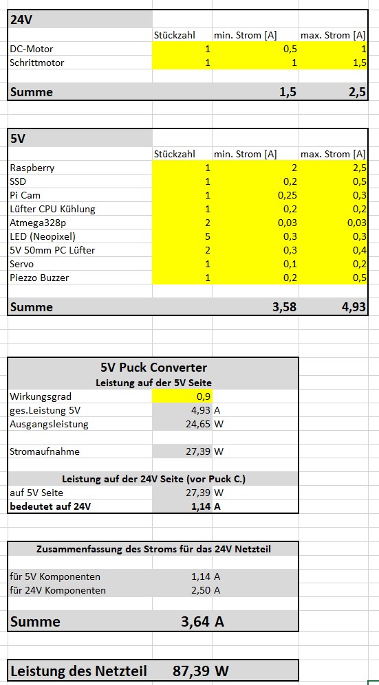
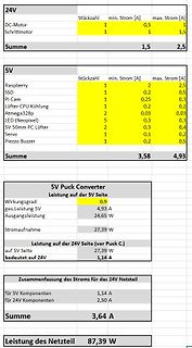
24V
DC-Motor
Schrittmotor
Summe
5V
Raspberry
SSD
Pi Cam
Lüfter CPU Kühlung
Atmega 328 p
LED (Neopixel)
5V 50mm PC Lüfter
Servo
Piezo Buzzer
Summe
5V Puck Converter
Leistung auf der 5V Seite
ges.Leistung 5V
Ausgangsleistung
Stromaufnahme
Leistung auf der 24V Seite (vor Puck C.)
auf
in
„Auswahl Bulk Kondesatoren“
·
Platinen
·
15.08.2025 11:58
·
Screenshots
Bild
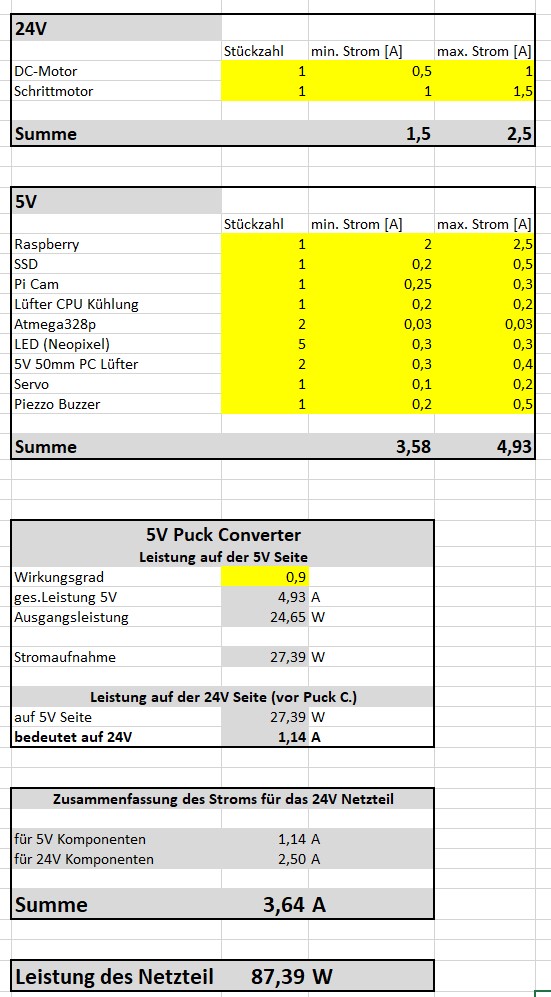
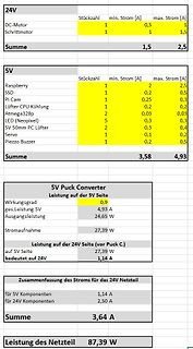
24V
DC-Motor
Schrittmotor
Summe
5V
Raspberry
SSD
Pi Cam
Lüfter CPU Kühlung
Atmega 328 p
LED (Neopixel)
5V 50mm PC Lüfter
Servo
Piezo Buzzer
Summe
5V Puck Converter
Leistung auf der 5V Seite
ges.Leistung 5V
Ausgangsleistung
Stromaufnahme
Leistung auf der 24V Seite (vor Puck C.)
auf
in
„Auswahl Bulk Kondesatoren“
·
Platinen
·
24.08.2025 17:18
·
Screenshots
Cinch 2x OPA1632 PCM4202 analog input stage AD conversno display I2S 2x16 characters analog SPDIF ATmega 328 other incremental control for volume and input
in
„Multiplexer für I2S“
·
Analoge Elektronik und Schaltungstechnik
·
30.10.2008 19:40
fuer StopWatch/TimeLog Instrument ' mit Zeit-Akkumulierung ' const F_CPU = 16000000 avr.device = atmega 328 p avr.clock = F_CPU avr.stack = 100 uart0.baud = 115200 uart0.Send.enable do ' some code ' some code print ">11<"; 'Ch1 Reset/Start Timing waitms 150 'Zu messender Code-Abschnitt 'durch waitms simuliert
in
„Projekt: Virtuelle Instrumente an serielle Schnittstelle“
·
Projekte & Code
·
14.07.2014 19:44
Bild
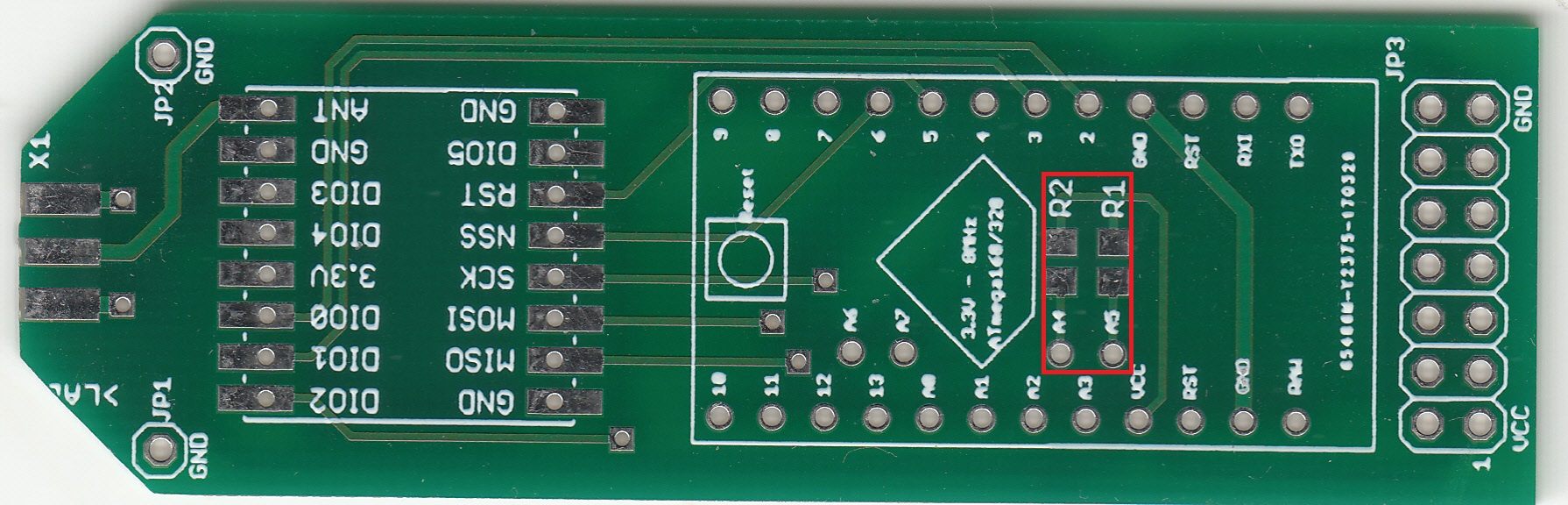
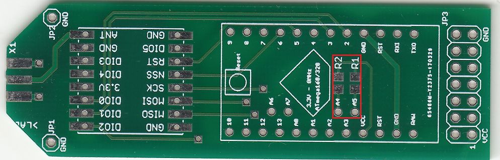
RST DI05 GND 9 8 7 5 3 2 GND RST RXI TXD GND JP3 GND VCC 1 10 11 A6 A5 A4 A3 A2 A1 A8 A7 A9 2.5V ATmega 168/328 R2 R1
in
„LoRaWAN: Nucleon Base Node“
·
Mikrocontroller und Digitale Elektronik
·
23.05.2024 12:01
·
Platinenfotos
//ATMEGA 328 #define F_CPU 8000000UL #include <avr/io.h> #include <avr/interrupt.h> #include <util/delay.h> #include <stdlib.h> #include <string.h> #include "uart.h" //Hier startet die Main int main(void) {
in
„UART läuft auf ATMEGA 32 aber nicht auf 328“
·
Mikrocontroller und Digitale Elektronik
·
18.11.2015 17:02
Bild
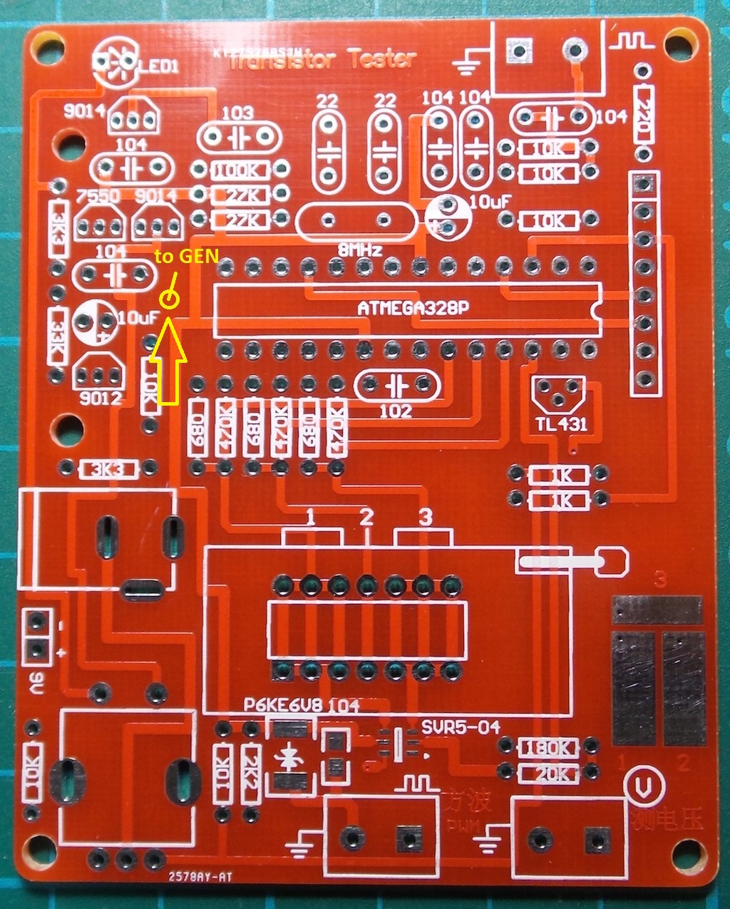
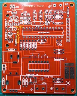
9014, 103, 22, 22, 104, 104, 104, 10K, 10K, 270, 10uF, 10K, 7550, 9014, 22K, 8MHz, 104, to GEN, ATMEGA 328 P, 10uF, 10K, 9012, 102, TL431, 470K, 470K, 470K, 680, 680, 3K3, 1K, 1K, 1, 2, 3, 3, P6KE6UB 104, SUR5-04, 180K, 20K, 9V, 10K, 22K, 2578AY-AT
in
„Transistortester AVR“
·
Projekte & Code
·
18.05.2023 18:33
·
Platinenfotos
Anzeige : 7-Segmentanzeige mit TM1637 Chip Widerstandssensor : KTY81-210. sonstiges : 2 Taster MCU: ATmega 328 p 09.03.2016 R. Seelig ---------------------------------------------------------- */ #include <util/delay.h> #include <avr/interrupt.h> #include <avr/io.h> #define widoffset 9; // Korrektur-Calibriermoeglichkeit
in
„Uhr mit TM1637 7-Segment Anzeige, KTY81-210 Temp.Sensor und ATmegaxx8“
·
Projekte & Code
·
17.03.2016 00:37
Bild
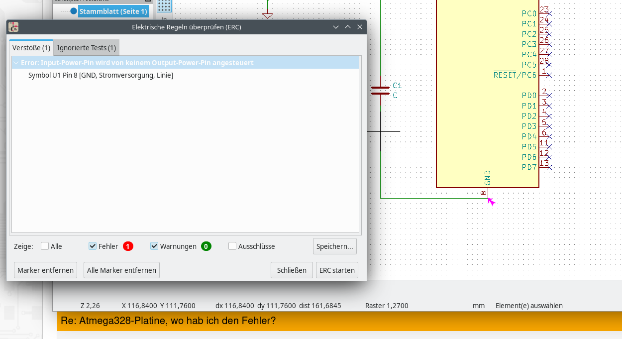
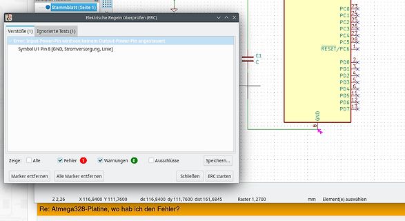
116,8400 Y 111,7600 dx 116,8400 dy 111,7600 dist 161,6845 Raster 1,2700 mm Element(e) auswählen Re: Atmega 328 -Platine, wo hab ich den Fehler?
in
„Atmega328-Platine, wo hab ich den Fehler?“
·
Mikrocontroller und Digitale Elektronik
·
08.06.2024 08:54
·
Screenshots
' Luna Beispiel : SerialComInstruments 8 LED Panel (#60) ' avr.device = atmega 328 p avr.clock = 16000000 avr.stack = 100 uart.baud = 115200 uart.Send.enable Dim i as byte do for i =0 to 255 step 1 print SendString(1,i); SendString(90,i); SendString(60,i) waitms 100 next loop '
in
„Projekt: Virtuelle Instrumente an serielle Schnittstelle“
·
Projekte & Code
·
30.10.2013 15:53
' Schnelles Signal-Display mit SerialComInstruments XY-Display avr.device = atmega 328 p avr.clock = 16000000 ' Quarzfrequenz avr.stack = 100 ' Bytes Programmstack (Vorgabe: 16) uart.baud = 115200 ' Baudrate uart.Recv.enable ' Senden aktivieren uart.Send.enable ' Empfangen aktivieren
in
„Projekt: Virtuelle Instrumente an serielle Schnittstelle“
·
Projekte & Code
·
15.12.2013 17:36
USB- USB+ DEBUG1 1 5 k F T R E 5 N 1 u S G 1 1 R R 0,1uF ATmega 328 ) 74HC595 e 1 n d : e a n l B z f - e n R1-10 2 m E - i 1,5kΩ t d e a - e 1 1 2 3 4 5 6 7 8 9 10 GND L I 2 26.08.17 08:55 f=3.56 /home/felix/eagle/arduino-sf.brd
in
„Wanderkiste Widlar, Runde II“
·
Markt
·
10.05.2018 17:53
Bild
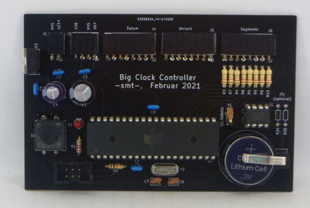
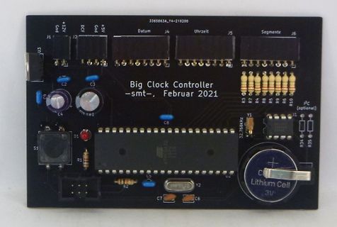
Controller
-smt-, Februar 2021
R7
R4
R8
R5
R9
R10
C4
CME
J1
(optional)
R3
C8
32,768kHz
Y1
S1
D1
R1
ATmega 328 P
32,768kHz
Lithium Cell
3V
C7
Y2
R2
C6
U2
in
„[V] Unvollendetes Bauprojekt "Große 7-Segment Uhr" (100 / 56mm)“
·
Markt
·
30.08.2026 12:44
·
Platinenfotos
Bild
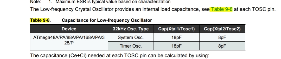
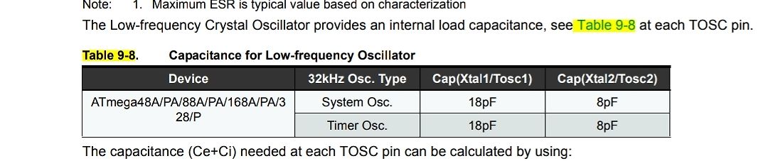
Capacitance for Low-frequency Oscillator
Device | 32kHz Osc. Type | Cap(Xtal1/Tosc1) | Cap(Xtal2/Tosc2)
ATmega 48A/PA/88A/PA/168A/PA/328 /P | System Osc. | 18pF | 8pF
| Timer Osc. | 18pF | 8pF
The capacitance (Ce+Ci) needed at each TOSC pin can be calculated by using:
in
„Schaltung Messung kleiner Ströme bei uC in Standby/Idle“
·
Analoge Elektronik und Schaltungstechnik
·
10.02.2024 12:04
·
Screenshots
Bild
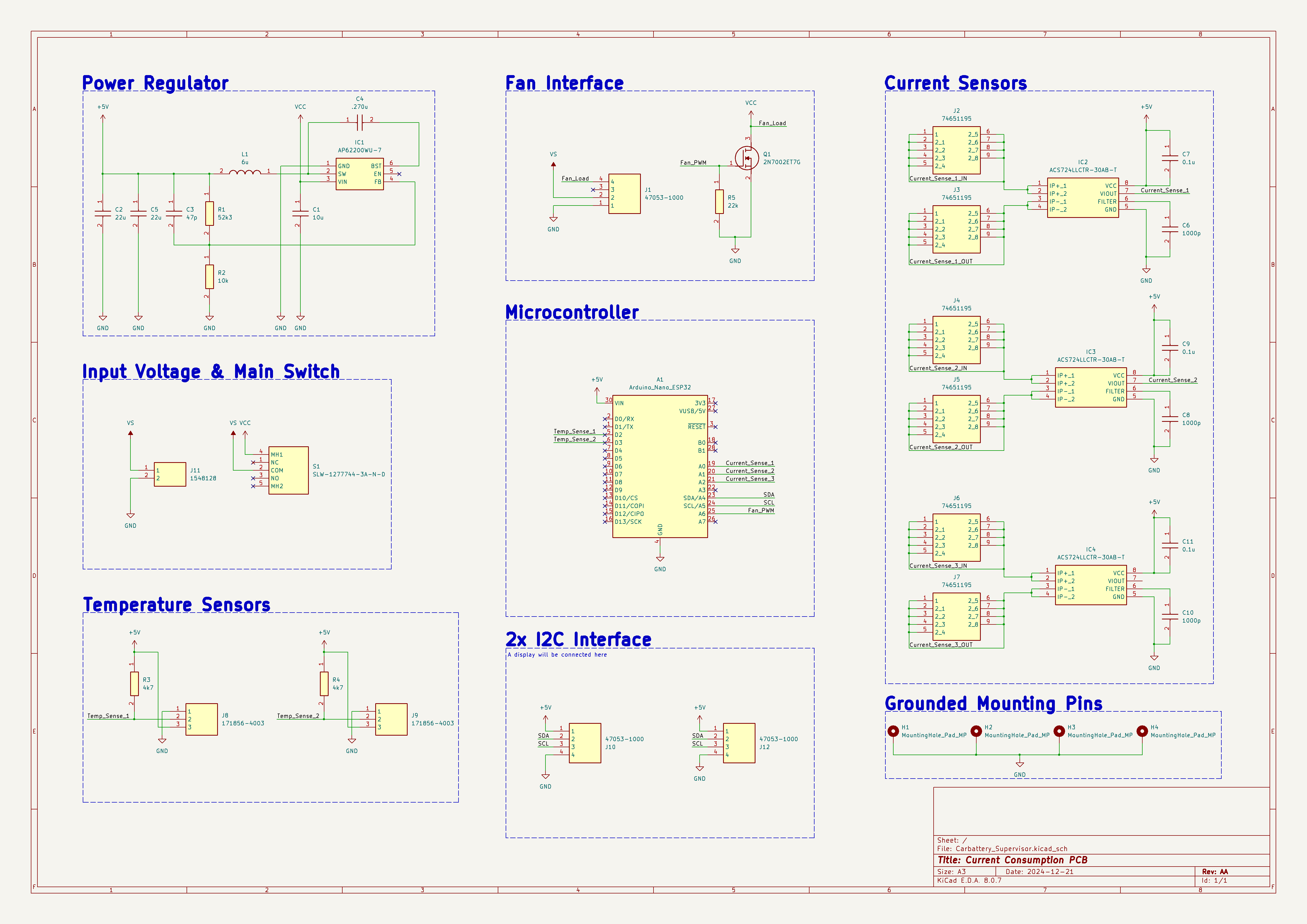
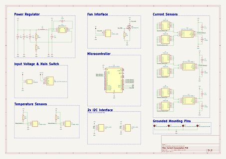
AC572LLCTR-306B-T, Input Voltage & Main Switch, VS, Q2, S1M-127774-3A-N-D, Microcontroller, Arduino_Nano_ATmega 328 P, Temp_Sense_1, Temp_Sense_2, A0 bis A7, I2C Interface, Temperature Sensors, R5, R6, Grounded Mounting Pins
in
„Verständisfrage Stromsensor“
·
Platinen
·
09.01.2025 19:31
·
Schaltpläne
' Beispiel Funktion für SerialComInstruments ' avr.device = atmega 328 p avr.clock = 16000000 avr.stack = 100 uart.baud = 115200 uart.Send.enable Dim i, f as single do ' Erzeugt Rampe (i) und Sinus (f) for i =0 to 6.28 step 0.02 f = fsin(i) print SendString(1,i);SendString
in
„Projekt: Virtuelle Instrumente an serielle Schnittstelle“
·
Projekte & Code
·
30.10.2013 00:34
Bild
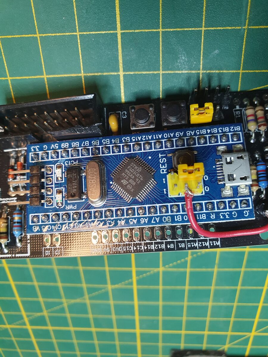
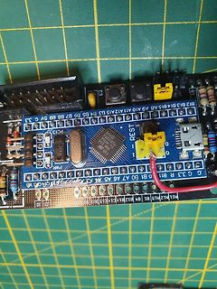
B6, B7, B8, B9, 5V, G, 3.3, B12, B13, B14, B15, A8, A9, A10, A11, A12, A15, B3, REST, PCT3, PWR, ATmega 328 P, 0, 1, B11, B10, B0, A7, A6, A5, A4, A3, A2, A1, A0, C4, C3, C2, C1, B1, B1, B12, B1, C14, C15, B3, 3, 1, 1, 1
in
„WordClock mit WS2812“
·
Projekte & Code
·
11.09.2023 20:14
·
Platinenfotos
Bild
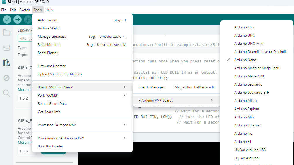
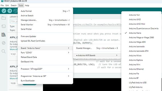
Root Certificates Board: "Arduino Nano" Port: "COM3" Reload Board Data Get Board Info Processor: "ATmega 328 P" Programmer: "Arduino as ISP" Burn Bootloader Arduino Yún Arduino UNO Arduino UNO Mini Arduino Duemilanove or Diecimila Arduino Nano Arduino Mega or Mega 2560 Arduino Mega ADK Arduino Leonardo
in
„anfänger-Problem mit arduino“
·
Mikrocontroller und Digitale Elektronik
·
22.08.2026 14:56
·
Screenshots
Bild
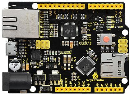
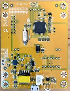
C21, R22, Y3, U6, ON, C10, U12, C11, U13, PC5, R18, R17, C24, C26, C23, R41, R40, R39, C25, USB, ATmega 328 P, 35V, AMS1117, 5V, GND, Vin, A0, A1, A2, A3, A4, A5, RESET, 3.3V, GND, keyestudio
in
„Keyestudio KS0304 Schaltplan“
·
Mikrocontroller und Digitale Elektronik
·
31.03.2026 10:42
·
Platinenfotos
avr.device = atmega 328 p avr.clock = 16000000 avr.stack = 100 uart.baud = 115200 uart.Send.enable Dim i as byte Dim f as Single do for i =1 to 100 f = i/100 Print "#1M" ; Str(i) ; "<" ; "#2M" ; Str(f) ; "<" Print "#3M"
in
„Projekt: Virtuelle Instrumente an serielle Schnittstelle“
·
Projekte & Code
·
21.10.2013 22:19
Bild
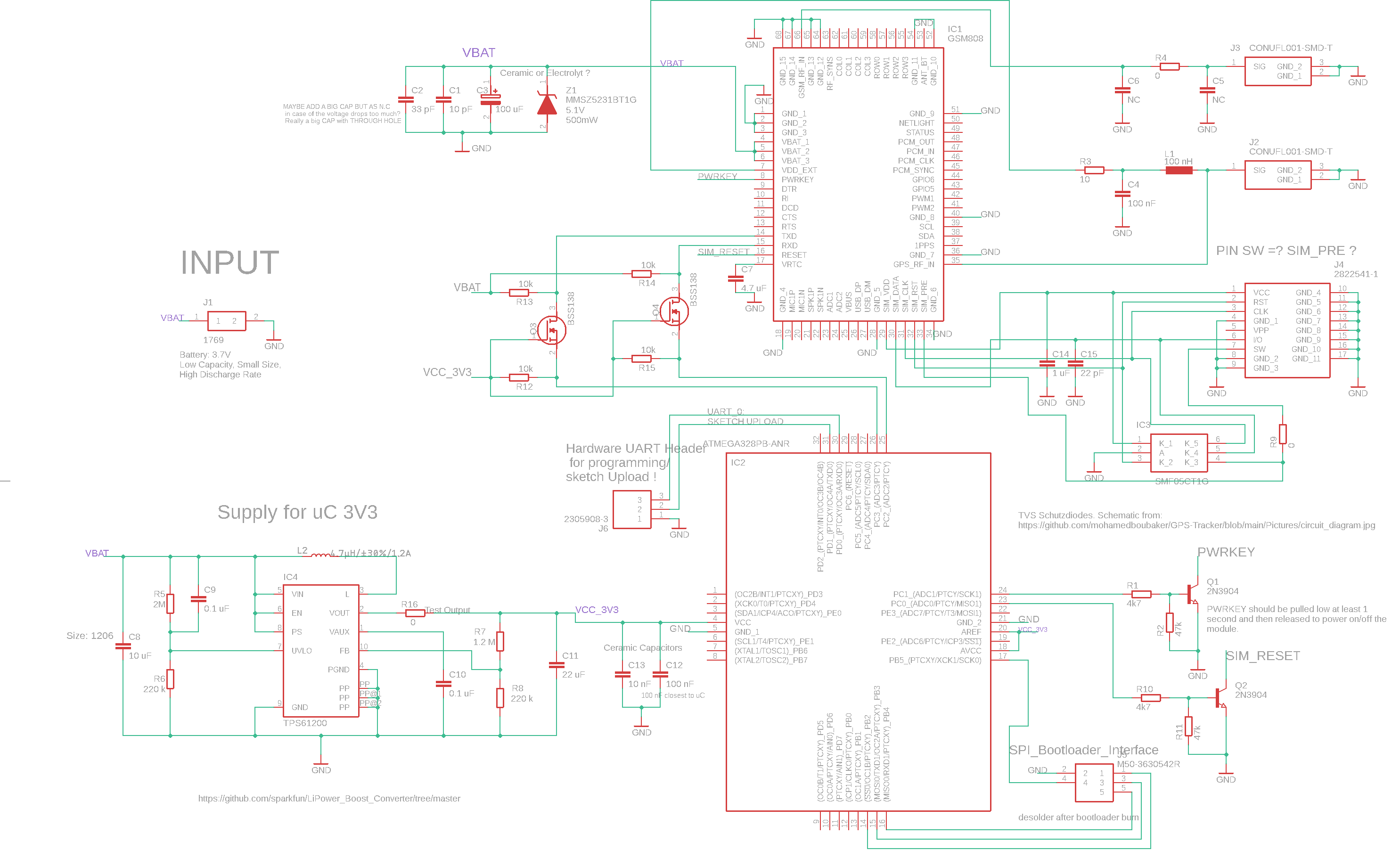
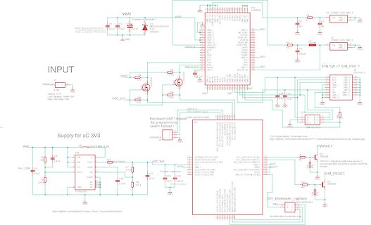
programming sketch Upload!, IC1 GSM268, SIM_RESET, PWRKEY, J3 CONN1_001-SIMO-T, J2 CONN1_001-SIMO-T, IC2 ATMEGA 328 P-AU, SPI_Bootloader_interface, IC4, L2, 1.2uF/1.2A, VCC_3V3, IC3, 2305BG-3, GND, 220 k, 10 uF, 0.1 uF, 100 nF, 22 uF, 10 mF, 100 nF, 47, 47, 220 k, 47, 47, 2N3904, 2N3904, TPS61200
in
„Feedback zu meiner Schaltung“
·
Mikrocontroller und Digitale Elektronik
·
21.12.2024 01:47
·
Schaltpläne
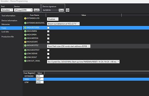
Bild
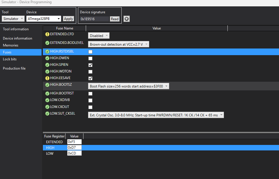
Simulator - Device Programming
Tool Device
Simulator ATmega 328 PB Apply
Device signature 0x1E9516 Read
Tool information Fuse Name Value
EXTENDED.CFD Disabled
Device information EXTENDED.BODLEVEL Brown-out detection at VCC=2.7 V
Memories HIGH.RSTDISBL
Fuses HIGH.DWEN
in
„ATMega328PB lässt sich nur noch programmieren. Sonst keine Funktion mehr“
·
Mikrocontroller und Digitale Elektronik
·
14.06.2025 13:41
·
Screenshots
#include <avr/io.h> // die Arduino typische LED an PB5 // UNO, Nano und ProMini (alle ATMega 328 P) // bei 16MHz Takt wird mit ca 0,5Hz an PB5 gewackelt outpin = PB5 .section .text .global main .global TIMER1_OVF_vect main: sbi _SFR_IO_ADDR(DDRB), outpin ; ; timer1 initialisieren ldi r24 , 0
in
„AVR Assembler Probleme mit Power Down Code“
·
Mikrocontroller und Digitale Elektronik
·
20.08.2019 12:23
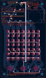
Bild
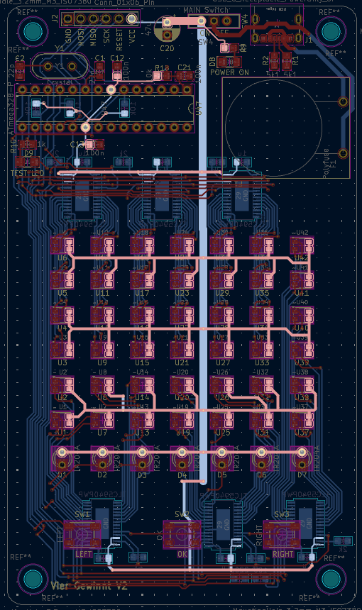
R34, R35, R36, R37, R38, R39, R40, R41, R42, U1 bis U42, D1 bis D6, SW1 bis SW3, LEFT, OK, RIGHT, ATmega 328 P, 100n, PolyFuse F1, Vier Gewinn V2
in
„TLC5940 (6x kaskadiert) – LED blinkt nur kurz beim Einschalten, danach keine Funktion“
·
Mikrocontroller und Digitale Elektronik
·
30.03.2026 21:53
·
Layouts
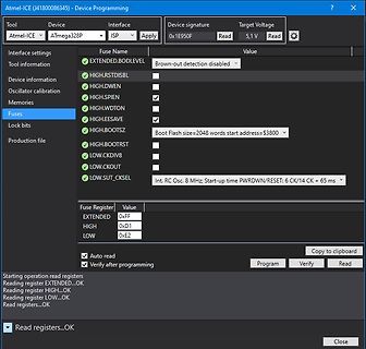
Bild
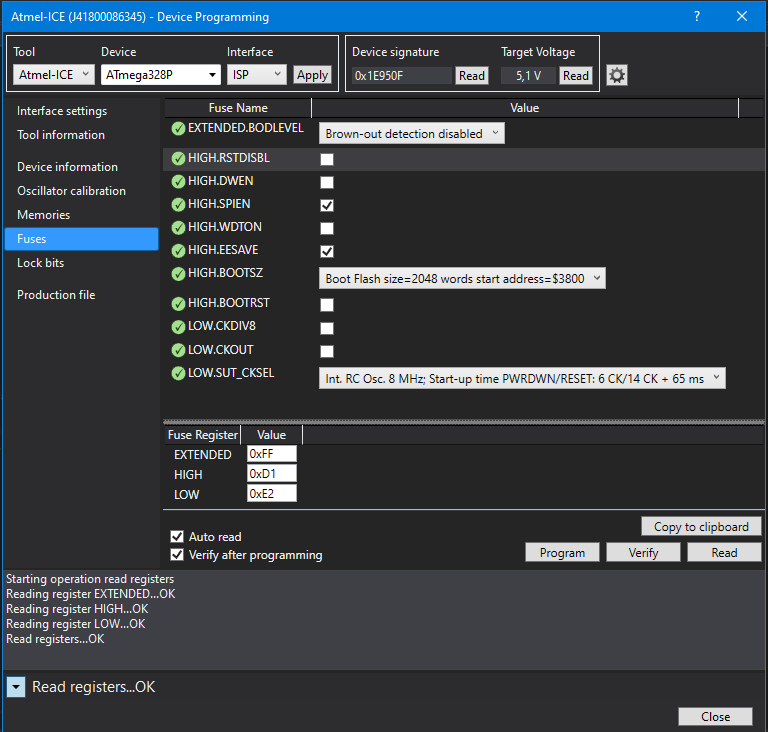
Atmel-ICE (J41800086345) - Device Programming
Tool: Atmel-ICE
Device: ATmega 328 P
Interface: ISP
Device signature: 0x1E950F
Target Voltage: 5,1 V
Fuse Name
Value
EXTENDED: Brown-out detection disabled
HIGH.RSTDISBL
HIGH.DWEN
HIGH.SPIEN
HIGH.WDTON
HIGH.EESAVE
HIGH.BOOTSZ: Boot
in
„Atmega328p und DS1307“
·
Mikrocontroller und Digitale Elektronik
·
23.08.2023 08:11
·
Screenshots
' Beispiel Funktion für SerialComInstruments ' avr.device = atmega 328 p avr.clock = 16000000 '22118400 avr.stack = 100 uart.baud = 115200 uart.Send.enable Dim i, f as single do ' Erzeugt Rampe (i) und Sinus (f) for i =0 to 6.28 step 0.1 f = fsin(i) print SendString
in
„Projekt: Virtuelle Instrumente an serielle Schnittstelle“
·
Projekte & Code
·
06.11.2013 06:30
-g -Os -w -fno-exceptions -ffunction-sections -fdata-sections -fno-threadsafe-statics -MMD -mmcu=atmega 328 p -DF_CPU=16000000L -DARDUINO=10605 -DARDUINO_AVR_UNO -DARDUINO_ARCH_AVR -IC:\Program Files (x86)\Arduino\hardware\arduino\avr\cores\arduino -IC:\Program Files (x86)\Arduino\hardware\arduino\avr\
in
„Arduino Uno und analoge Märklin-Weichen“
·
Mikrocontroller und Digitale Elektronik
·
28.03.2016 09:31
avrdude -c avrdude.conf -v -p m328 p -c stk500v2 -P com3 -b115200 -D -U flash:w:grbl_display.hex:i -vvv avrdude: Version 6.3, compiled on Jan 17 2017 at 12:00:53 Copyright (c) 2000-2005 Brian Dean, http://www.bdmicro.com/ Copyright (c
in
„ATMega328P für MaXYposi flashen“
·
Mikrocontroller und Digitale Elektronik
·
12.11.2017 16:22
======================= #if use_usart_tft int init_usart_spi(void) { // DDRB = (1<<PB0); // XCK0 ATMega 644 DDRD |= (1<<PD4); // XCK0 ATMega 328 DDRD &=~(1<<PD0);//rx-miso DDRD |= (1<<PD1);//tx-mosi // 1. Set baud Rate Register to 0 UBRR0 = 0x0000; // 2. Set XCK line to output mode // 3. Select Master
in
„TFT_ILI9163C mit Arduino richtig verbinden“
·
Mikrocontroller und Digitale Elektronik
·
25.03.2016 07:25
Bild
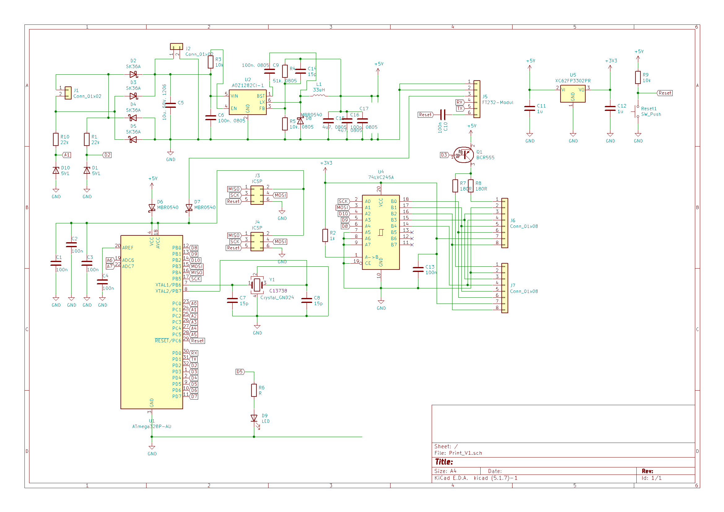
22V, A1, D10 5V1, GND, C1 100n, R1 33k, C5, GND, D7 MBR0540, D6 MBR0540, ACC, RESET, PB0 bis PB7, ATmega 328 P-AU, C7 15p, Crystal, GND, D5, R6, D9 LED, C14 15u, L1 33u, U2 AOZ1282, C6 100n, C17, Reset, U4 74LVC254A, A0 bis A7, B0 bis B7, C0 bis C3, C13 100n, U5 XC62P302P2, C11, C12, Reset, Sw_Push, GND
in
„ATmega328P resettet bei I/O Zugriff“
·
Mikrocontroller und Digitale Elektronik
·
10.06.2023 20:22
·
Schaltpläne
/* Name: Test "key-routines.h" µC: ATmega 328 P Date: Nov 2017 */ #define F_CPU 16000000 #include <avr/io.h> #include "key-routines.h" int main(void) { KEY_DDR &= ~ALL_KEYS; // configure key port for input KEY_PORT |= ALL_KEYS; // and turn on
in
„[C] Einbindung der Entprellroutine als Header-Datei?“
·
Mikrocontroller und Digitale Elektronik
·
21.11.2017 19:08
Bild
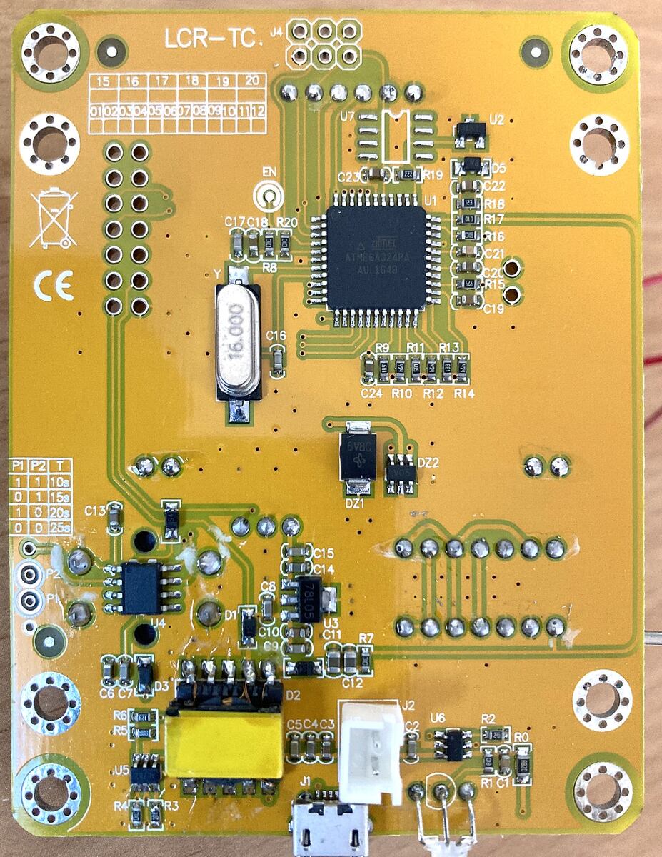
U4 15 16 17 18 19 20 01 02 03 04 05 06 07 08 09 10 11 12 CE U7 C23 R19 U2 C22 R18 R17 R16 C21 U1 ATMEGA 328 PA AU 1640 R8 C15 R15 C19 R9 R11 R13 R10 R12 R14 C24 16.000 P1 P2 T 1 1 10s 0 1 15s 1 0 20s 0 0 25s C13 DZ2 DZ1 C15 C14 C8 U3 C10 C11 R7 U4 C6 C7 D3 D2 D2 U2 C2 C1 R0 R1 C1 U5 R4 R3 J1
in
„Mikrocontroller M-Tester, welche Hardware?“
·
Mikrocontroller und Digitale Elektronik
·
03.01.2026 11:22
·
Platinenfotos
Bild
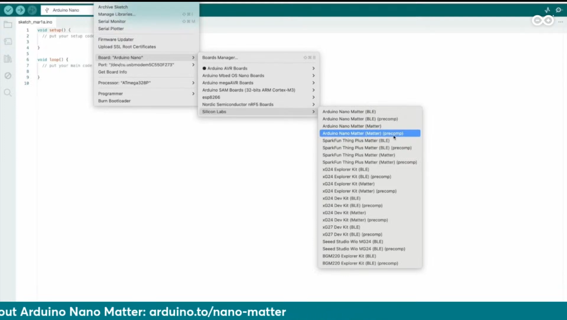
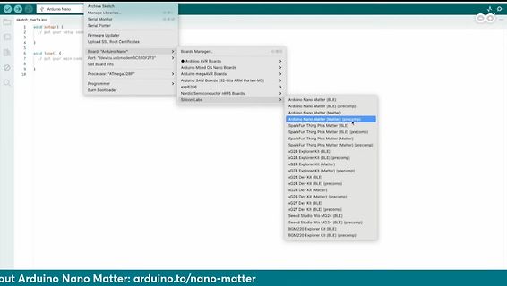
Arduino Nano
sketch_marta.ino
void setup() {
}
void loop() {
}
Board: "Arduino Nano"
Processor: "ATmega 328 P"
Boards Manager...
Arduino AVR Boards
Arduino Mbed OS Nano Boards
Arduino megaAVR Boards
Arduino SAM Boards (32-bits ARM Cortex-M3)
ESP32
Nordic Semiconductor nRF5 Boards
Arduino Nano Matter (BLE
in
„Arduino Days: Neuer Matter-Arduino, Erweiterungen für Arduino-SPS und Cloud“
·
Mikrocontroller und Digitale Elektronik
·
27.03.2024 23:01
·
Screenshots
Bild
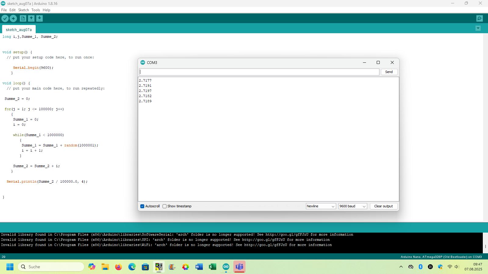
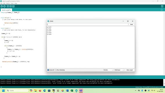
\Program Files (x86)\Arduino\libraries\WiFi: 'arch' folder is no longer supported!
Arduino Nano, ATmega 328 P (Old Bootloader) on COM
in
„Physikprojekte“
·
Offtopic
·
07.08.2025 09:58
·
Screenshots
************ Beispiel Funktion für SerialComInstruments mit dem Arduino Duemilanove avr.device = atmega 328 p avr.clock = 16000000 uart.baud = 38400 Datum : 06.11.2013 Autor : Dipl.Ing. gatsby *******************************************************************************/ // Senden eines Telegramms an
in
„Projekt: Virtuelle Instrumente an serielle Schnittstelle“
·
Projekte & Code
·
06.11.2013 15:09
#include <avr/io.h> // die Arduino typische LED an PB5 // UNO, Nano und ProMini (alle ATMega 328 P) // bei 16MHz Takt wird mit ca 0,5Hz an PB5 gewackelt outpin = PB5 // Arduino LED_BUILTIN work = 24 // Arbeitsregister .section .text,"ax",%progbits // https://www.nongnu.org/avr-libc/user-manual
in
„Einfache CPU, einfacher Rechner, nur zum Lernen, Erfahrung?“
·
Mikrocontroller und Digitale Elektronik
·
21.10.2024 12:42
/* Name: Test "key-routines.h" µC: ATmega 328 P Date: Nov 2017 */ #define F_CPU 16000000 #include <avr/io.h> #include <avr/interrupt.h> #include "key-routines.h" int main(void) { KEY_DDR &= ~ALL_KEYS; // configure key port for input KEY_PORT
in
„[C] Einbindung der Entprellroutine als Header-Datei?“
·
Mikrocontroller und Digitale Elektronik
·
21.11.2017 20:19
set -e; avr-gcc -MM -mmcu=atmega 328 p -I. -g -Os -funsigned-char -funsigned-bitfields -fpack-struct -fshort-enums -Wall -Wstrict-prototypes -Wa,-adhlns=main.lst -std=gnu99 -fno-inline-small-functions main.c \ | sed 's,\(.*\)\.o[ :]
in
„ADC in C unter WinAVR ärgert“
·
Mikrocontroller und Digitale Elektronik
·
21.09.2014 09:59
Bild
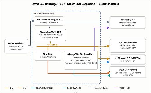
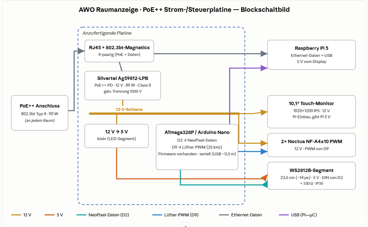
10,1" Touch-Monitor
1920x1200 IPS · 12 V
Pi-Einbau, gibt Pi 5 V
12 V -> 5 V
klein (LED-Segment)
ATmega 328 P / Arduino Nano
D2 -> NeoPixel-Daten
D9 -> Lüfter-PWM (25 kHz)
Firmware vorhanden · seriell (USB ~0,5 m)
2x Noctua NF-A4x10 PWM
12 V · PWM von D9
WS2812B-Segment
23,5 cm (~14 px) · 5 V · DIN von
in
„Projekt AWO-Raumanzeige — Hilfe/Umsetzung einer PoE++ Strom- & Steuerplatine gesucht (Raspberry Pi)“
·
Platinen
·
14.06.2026 18:38
·
Diagramme
// Timer 1 für ATmega 328 . #define F_CPU 3686400 #include <avr\io.h> #include <avr\interrupt.h> //-------------------------------------------------------------------- // INT1_vect - INT1 Interrupt an Eingang PORTD3 bei
in
„Fehler beim Kompilieren“
·
Mikrocontroller und Digitale Elektronik
·
23.06.2012 17:13
// Atmega 328 p intern 1 Mhz #define F_CPU 1000000UL #include <avr/io.h> #include <util/delay.h> #include <avr/interrupt.h> #include <avr/power.h> #include <avr/wdt.h> #include <avr/sleep.h> #include "rfm69.c"
in
„Atmega328p in Sleep und mit Watchdog wecken“
·
Mikrocontroller und Digitale Elektronik
·
28.09.2017 19:34
2016 06:38 AM (UTC) by Nick Gammon Message This article discusses interrupts on the Arduino Uno (Atmega 328 ) and similar processors, using the Arduino IDE. The concepts however are very general. The code examples provided should compile on the Arduino IDE (Integrated Development Environment). This page
in
„Verständnis AVR Interrupts“
·
Mikrocontroller und Digitale Elektronik
·
22.09.2020 23:22
Tasteninterface. Geeignet fuer: TM1651, TM1637 MCU : alle AVR ( getestet ATtiny85, ATtiny2313, ATtiny44, ATmega 8, ATmega 328 p ) F_CPU : 8 MHz intern Pinbelegung Controller TM16xx --------------------------- PB1 CLK PB0 DIO CLK und DIO sind mit jeweils 2,2 kOhm Pop-Up Wider- staenden nach +5V zu versehen 10.01.2019
in
„Siebensegment und Tasten ansteuern mit TM1651 \ TM1637“
·
Projekte & Code
·
15.01.2019 19:28
**************************************************************************** // //Initalisierung ATmega 328 // //**************************************************************************** #include <avr/io.h> #include <stdint.h> #include <avr/wdt.h> #include <avr/interrupt.h> //**********************
in
„Initialisierung EADOGS 204-N via SPI“
·
Mikrocontroller und Digitale Elektronik
·
13.07.2026 11:34
// for Atmega 328 P - Arduino Nano //int readVcc() { // int result; // Read 1.1V reference against AVcc // ADMUX = _BV(REFS0) | _BV(MUX3) | _BV(MUX2) | _BV(MUX1); // delay(2); // Wait for Vref to settle // ADCSRA
in
„Messen der uC_eigenen Ub mit Arduino Nano“
·
Analoge Elektronik und Schaltungstechnik
·
10.07.2020 16:23
/* Test des Free run mode im ADC ATmega 328 P, aka Arduino Uno/Micro/Nano */ #define F_CPU 16000000UL #include <avr/io.h> #include <avr/interrupt.h> #include <avr/sleep.h> #define FREERUN // ADC initialisieren void adc_init(void) { ADMUX =
in
„ADC-Kanäle sukzessive abfragen“
·
Mikrocontroller und Digitale Elektronik
·
24.05.2025 13:07
Apfelmaennchen 160x128 Pixel Optimierung -Os 62,9s / 6388 Byte -O3 62,8s / 7664 Byte Benchmark Ergebnisse ATmega 328 Compiler: avr-gcc Version 7.3.0 | Zeit [s] | Optimierung | int8 | int16 | int32 | float | Codegroesse | --------------------------------------------------------------------------- -Os | 15,0 | 46,0
in
„CH32V003, float wirklich langsam?“
·
Mikrocontroller und Digitale Elektronik
·
21.11.2025 00:00
Apfelmaennchen 160x128 Pixel Optimierung -Os 62,9s / 6388 Byte -O3 62,8s / 7664 Byte Benchmark Ergebnisse ATmega 328 Compiler: avr-gcc Version 7.3.0 | Zeit [s] | Optimierung | int8 | int16 | int32 | float | Codegroesse | --------------------------------------------------------------------- -Os | 16,81 | 48,2 |
in
„CH32V003, float wirklich langsam?“
·
Mikrocontroller und Digitale Elektronik
·
21.11.2025 01:04
Apfelmaennchen 160x128 Pixel Optimierung -Os 62,9s / 6388 Byte -O3 62,8s / 7664 Byte Benchmark Ergebnisse ATmega 328 Compiler: avr-gcc Version 7.3.0 | Zeit [s] | Optimierung | int8 | int16 | int32 | float | Codegroesse | --------------------------------------------------------------------- -Os | 16,81 | 48,2 |
in
„CH32V003, float wirklich langsam?“
·
Mikrocontroller und Digitale Elektronik
·
21.11.2025 01:25
// SLdt 180820 // 1 s-Impuls per "Uhrenquarz" 32 KiHz an TOSC1&2 // ATmega 328 P Werksfuses #define F_CPU 1000000UL #include <avr/io.h> #include <avr/sleep.h> #include <avr/interrupt.h> uint8_t tmp; int main (void) { DDRB = 1; // Kontroll-LED an B0 ASSR = (1<<AS2); // asynchron
in
„Mit Uhrenquarz Takt vorgeben“
·
Mikrocontroller und Digitale Elektronik
·
20.08.2018 07:02

 Bild
Bild
 Bild
Bild
 Bild
Bild
 Bild
Bild
 Bild
Bild
 Bild
Bild
 Bild
Bild
 Bild
Bild
 Bild
Bild
 Bild
Bild
 Bild
Bild
 Bild
Bild
 Bild
Bild
 Bild
Bild
 Bild
Bild
 Bild
Bild
 Bild
Bild
 Bild
Bild
 Bild
Bild
 Bild
Bild