-
Datei
A.txt
von Impulsen mit variabler Frequenz (von ADC abhängig) aber konstantem Tastverhältni (50%) ///// //ATmega8///// #ifndef F_CPU /* prevent compiler error by supplying a default */ #define F_CPU 1000000UL #endif #include <util/delay.h> #include <avr/interrupt.h> #include <avr/io.h> char pulselength; char
in „Interupt Routine leicht gemacht?“ · Mikrocontroller und Digitale Elektronik ·
-
Datei
waterdrop-experiment.c
/ all low DDRB = 0x00; // switches PORTB = 0xff; // enable internal pullups // With a prescaler of 64, the ADC clock results to 8MHz/64 = 125Khz. // A single conversion takes from 13-260us due to the successive approximation // (depending on the actual voltage level at the ADC input channel). ADCSRA = (1 << ADEN) | (1 << ADPS1) | (1 << ADPS2) | (1 << ADIE); // prescaler: 64 ADMUX = 0; // select ADC0 as source and choose AREF as reference ADCSRA |= (1 << ADSC) | (1 << 5); sei(); // enable interrupts }
in „LED als Sensor“ · Mikrocontroller und Digitale Elektronik ·
-
Datei
Pulsweite_messen.txt
'Testprogramme mit T6963C graphic display 160 x 64 Dot 'Pulsweite von DCF77 Ausgang messen und ausgeben 'µC Atmega32 / Takt 1Mhz / Flash 32Kb '----------------------------------------------------------------- 'Pinbelegung 'LCD pin Signal Verbunden Portbelegung
in „Falsche Werte bei Pulsweite messen“ · Mikrocontroller und Digitale Elektronik ·
-
Datei
avr_oscilloscope_1_.htm
MARGIN-BOTTOM: 0px">12V DC</P> <P style="LINE-HEIGHT: 100%; MARGIN-TOP: 0px; MARGIN-BOTTOM: 0px">128x64 pixels</P> <P style="LINE-HEIGHT: 100%; MARGIN-TOP: 0px; MARGIN-BOTTOM: 0px">100x64 pixels</P> </TD> </TR> </TBODY></TABLE> </TD> </TR> </TBODY></TABLE> <P style="LINE-HEIGHT: 100%; MARGIN-TOP: 0px;
in „AVR-OZZI_fuses_help“ · Mikrocontroller und Digitale Elektronik ·
-
Datei
Makefile.txt
SCANF_LIB_FLOAT = -Wl,-u,vfscanf -lscanf_flt SCANF_LIB = MATH_LIB = -lm # External memory options # 64 KB of external RAM, starting after internal RAM (ATmega128!), # used for variables (.data/.bss) and heap (malloc()). #EXTMEMOPTS = -Wl,-Tdata=0x801100,--defsym=__heap_end=0x80ffff # 64 KB of external RAM, starting after internal RAM (ATmega128!), # only used for heap (malloc()). #EXTMEMOPTS = -Wl,--defsym=__heap_start=0x801100,--defsym=__heap_end=0x80ffff EXTMEMOPTS = # Linker flags. # -Wl,...: tell GCC to pass this to linker. # -Map:
in „Hilfe bei Programmierung“ · Mikrocontroller und Digitale Elektronik ·
-
Datei
Makefile.txt
SCANF_LIB_FLOAT = -Wl,-u,vfscanf -lscanf_flt SCANF_LIB = MATH_LIB = -lm # External memory options # 64 KB of external RAM, starting after internal RAM (ATmega128!), # used for variables (.data/.bss) and heap (malloc()). #EXTMEMOPTS = -Wl,-Tdata=0x801100,--defsym=__heap_end=0x80ffff # 64 KB of external RAM, starting after internal RAM (ATmega128!), # only used for heap (malloc()). #EXTMEMOPTS = -Wl,--defsym=__heap_start=0x801100,--defsym=__heap_end=0x80ffff EXTMEMOPTS = # Linker flags. # -Wl,...: tell GCC to pass this to linker. # -Map:
in „Programmers notepad - probleme bei make all“ · Mikrocontroller und Digitale Elektronik ·
-
Datei
lcd.h
for Enable line */ #elif defined(__AVR_AT90S4414__) || defined(__AVR_AT90S8515__) || defined(__AVR_ATmega64__) || \ defined(__AVR_ATmega8515__)|| defined(__AVR_ATmega103__) || defined(__AVR_ATmega128__) || \ defined(__AVR_ATmega161__) || defined(__AVR_ATmega162__) || defined(__AVR_AT90S4433__) /* * memory
in „winziges Problem“ · Mikrocontroller und Digitale Elektronik ·
-
Datei
lcd.h
#if LCD_IO_MODE #elif defined(__AVR_AT90S4414__) || defined(__AVR_AT90S8515__) || defined(__AVR_ATmega64__) || \ defined(__AVR_ATmega8515__)|| defined(__AVR_ATmega103__) || defined(__AVR_ATmega128__) || \ defined(__AVR_ATmega161__) || defined(__AVR_ATmega162__) /* * memory mapped mode is only supported
in „DCF auf INT0“ · Mikrocontroller und Digitale Elektronik ·
-
Datei
mw_lcd.h
#if LCD_IO_MODE #elif defined(__AVR_AT90S4414__) || defined(__AVR_AT90S8515__) || defined(__AVR_ATmega64__) || \ defined(__AVR_ATmega8515__)|| defined(__AVR_ATmega103__) || defined(__AVR_ATmega128__) || \ defined(__AVR_ATmega161__) || defined(__AVR_ATmega162__) /* * memory mapped mode is only supported
in „DCF auf INT0“ · Mikrocontroller und Digitale Elektronik ·
-
Datei
ohne_kontrollausgabe.asm
to be called before setup() or some functions won't // work there sei(); 4b8: 78 94 sei // on the ATmega168, timer 0 is also used for fast hardware pwm // (using phase-correct PWM would mean that timer 0 overflowed half as often // resulting in different millis() behavior on the ATmega8 and ATmega168)
in „AVR Inline Optimierung kaputt?“ · Mikrocontroller und Digitale Elektronik ·
-
PDF
AdvancedUseAVRASM2_de_20171104.pdf
wird.. 13. Beispiel für eine Entwicklung-Umgebung unter Windows Ich entwickle unter Windows 10 Pro 64-Bit und nutze AVRASM2 von der Kommandozeile oder aus EMACS heraus. Dazu habe ich das zugehörige Unterverzeichnis im passenden Ordner von "Program Files" "installiert" (bzw. Program Files (x86) bei 64
in „Advanced Use of AVRASM2“ · Mikrocontroller und Digitale Elektronik ·
-
PDF
AdvancedUseAVRASM2_de_20171104.pdf
wird.. 13. Beispiel für eine Entwicklung-Umgebung unter Windows Ich entwickle unter Windows 10 Pro 64-Bit und nutze AVRASM2 von der Kommandozeile oder aus EMACS heraus. Dazu habe ich das zugehörige Unterverzeichnis im passenden Ordner von "Program Files" "installiert" (bzw. Program Files (x86) bei 64
in „Doku zu AVR Assembler für komplexe Projekte (deutsch)“ · Projekte & Code ·
-
PDF
readme_131206.pdf
Lib in Python3.2 (für XBee ZB Module im API-Modus) Bislang sind meine Router und der Coordinator anATMega's angeschlossen und die Software ist in C geschrieben. Zumindest der Coordinator soll in Zukunft direkt an der serielle Schnittstelle eines PC's oder RaspberryPi's seinen Dienst tun, damit dort Daten
-
Datei
dude54arduino_mit_vvvv.txt
= ATMEGA64 avrdude: Recv: F [46] Device code: 0x46 = (unknown) avrdude: Recv: G [47] Device code: 0x47 = (unknown) avrdude: Recv: H [48] Device code: 0x48 = (unknown) avrdude: Recv: I [49] Device code: 0x49
in „avrdude - Probleme unter Mac OS X 10.7 (Lion)“ · Mikrocontroller und Digitale Elektronik ·
-
Datei
Zeit_T0_T2_01.c
//Zeitmessung mit Timer0 für INT0 und Timer2 für INT2 //AVR ATMega8 mit 11,0592 MHz-Quarz //64-Teiler=172800 Impulse pro Sekunde //Bei 50 Hz (20 msec) =3456 Impulse //Entspricht bei 2 msec 345 Impulse //*************************************************************
in „Timer0 und Timer2 verschiedene Werte.“ · Mikrocontroller und Digitale Elektronik ·
-
Datei
ADC_USART_Read_adc.c
+++++++++++++++++++++++++++++++++++++++++++++++++++++++ 8-Bit-Analog-Digital-Converter mit ATMEL ATmega8 to STK500 board, output on (PortB) --> LEDs Description: The ADC converts an analog input voltage to a 10-bit digital value through successive approximation. The minimum value represents GND and the
in „warnung:"[variable]may be used uninizialized"“ · Mikrocontroller und Digitale Elektronik ·
-
Datei
main.c
articles/AVR-Tutorial:_Timer //https://sites.google.com/site/qeewiki/books/avr-guide/timer-on-the-atmega8 //1MHz/64 = 15625 //1Mhz/64/15625 = 1s // CTC Mode | Prescaler 64 TCCR1B |= (1<<WGM12) | (1<<CS11) | (1<<CS10); OCR1A = 15624; //Vorladewert TIMSK |= (1<<OCIE1A); sei(); while (1) { Berechnen(); Zeigen
in „Interrupt Frage ATMEGA8535“ · Mikrocontroller und Digitale Elektronik ·
-
Datei
erase.txt
avrdude.conf" Using Port : \\.\COM2 Using Programmer : arduino Overriding Baud Rate : 19200 AVR Part : ATMEGA128 Chip Erase delay : 9000 us PAGEL : PD7 BS2 : PA0 RESET disposition : dedicated RETRY pulse : SCK serial program mode : yes parallel program mode : yes Timeout : 200 StabDelay : 100 CmdexeDelay :
in „ATMega128a verflasht Turigy 9xr“ · Mikrocontroller und Digitale Elektronik ·
-
Datei
t6963c.h
#define DDR(x) (*(&x - 1)) /* address of data direction register of port x */ #if defined(__AVR_ATmega64__) || defined(__AVR_ATmega128__) /* on ATmega64/128 PINF is on port 0x00 and not 0x60 */ #define PIN(x) ( &PORTF==&(x) ? _SFR_IO8(0x00) : (*(&x - 2)) ) #else #define PIN(x) (*(&x - 2)) /* address
-
Datei
t6963c.h
#define DDR(x) (*(&x - 1)) /* address of data direction register of port x */ #if defined(__AVR_ATmega64__) || defined(__AVR_ATmega128__) /* on ATmega64/128 PINF is on port 0x00 and not 0x60 */ #define PIN(x) ( &PORTF==&(x) ? _SFR_IO8(0x00) : (*(&x - 2)) ) #else #define PIN(x) (*(&x - 2)) /* address
-
PDF
doc8377.pdf
1284P Xplained kit. 3.1 Preprogrammed firmware The MEGA-1284P Xplained kit comes with both the Atmel ATmega1284P and the Atmel AT32UC3B1256 pr eprogrammed. The preprogrammed firmware in the ATmega1284P is set up with example code that allows the user to choose different sleep modes, and provides an example
in „[V] MEGA-1284P-XPLAINED“ · Markt ·
-
PDF
nRF24L01plus.pdf
2.4GHz-HowTo von der Beschreibung abweichend sind die folgenden Verbindungen: • nRF24L01+ CE → Arduino D8 (ATMega8 PB0) • nRF24L01+ CSN → Arduino D4 (ATMega8 PD4) • nRF24L01+ IRQ → Arduino D3 (ATMega8 PD3) Gaaaanz wichtig der 100µF Kondensator nahe bei der 3,3V Versorgung für den nRF24L01+ nicht vergessen. Die
in „Repeating und Routing Netzwerk mit Arduino und nRF24L01+“ · Projekte & Code ·
-
Datei
polli_rfm12_rx_tx_an_PC.c
include "onboard.h" #include "rfm12.h" #include "UART.h" // RFM12 Interrupt volatile uint8_t RFM_TX[64]; volatile uint8_t flTX_on=0; volatile uint8_t RFM_RX[64]; volatile uint8_t flRX_on=0; volatile uint8_t flRX_rec=0; volatile uint8_t flRX_ready=0; volatile uint8_t RX_crc=0; volatile uint8_t RX_count
in „RFM12 Statusabfrage“ · Mikrocontroller und Digitale Elektronik ·
-
 Bild
Bild
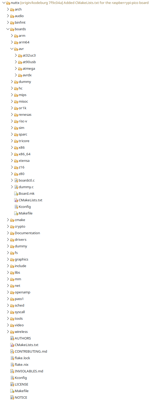
Verzeichnisstruktur eines Software-Projekts
7f9c04a] Added CMakeLists.txt for the raspberrypi-pico board arch audio binfmt boards arm arm64 avr at32uc3 at90usb atmega avrdx dummy hc mips misoc or1k renesas risc-v sim sparc tricore x86 x86_64 xtensa z80 boardctl.c dummy.c Board.mk CMakeLists.txt Kconfig Makefile
in „upyOS Betriebssystem Mikrocontroller“ · Mikrocontroller und Digitale Elektronik · · Screenshots
-
 Bild
Bild
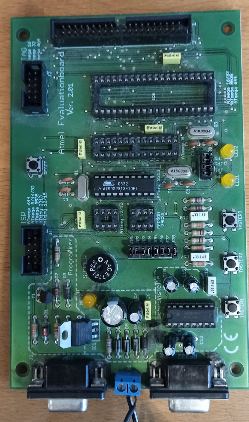
Atmel Evaluationboard Ver. 2.01 Leiterplatte
Atmel Evaluationboard Ver. 2.01 TAG ATmega 8/32 64 128 ISP ATmega 8/32 128/256 AT90S2313-10PI P22 AAC E121 PROGRAMMER ISP RS232
in „(V) Testboard“ · Markt · · Platinenfotos
-
Datei
ini.asm
; Bernhard.Erfurt@gmx.de ; 01/2021 ; ; ; 128 x 64 Pixel=8.192 Pixel :8=1024 ; ATmega328P ; 8MHz ;.include "m328pdef.inc" .include "MACROS.asm" .equ TAKT = 8000000 ; 8 MHz ; ERROR CODES .equ ERROR_TWI_MT_START =0x20 .equ ERROR_TWI_MT_SLA =0x21 .equ ERROR_TWI_MT_DATA
in „DEBO OLED2 0.96 0,96" OLED-Display SSD1306 SSD1312 Initialisierung TWI I2C AVR ATmeg8 Assembler ASM“ · Projekte & Code ·
-
Datei
ini.asm
; Bernhard.Erfurt@gmx.de ; 01/2021 ; ; ; 128 x 64 Pixel=8.192 Pixel :8=1024 ; ATmega328P ; 8MHz ;.include "m328pdef.inc" .include "MACROS.asm" .equ TAKT = 8000000 ; 8 MHz ; ERROR CODES .equ ERROR_TWI_MT_START =0x20 .equ ERROR_TWI_MT_SLA =0x21 .equ ERROR_TWI_MT_DATA
in „DEBO OLED2 0.96 0,96" OLED-Display SSD1306 SSD1312 Initialisierung TWI I2C AVR ATmeg8 Assembler ASM“ · Projekte & Code ·
-
Datei
uart.h
int baudrate); /** @brief Get received byte of USART1 from ringbuffer. (only available on selected ATmega) @see uart_getc */ extern unsigned int uart1_getc(void); /** @brief Put byte to ringbuffer for transmitting via USART1 (only available on selected ATmega) @see uart_putc */ extern void uart1_putc(unsigned
in „ATmega328p fehlerhafte UART-Anzeige mit bootloader“ · Mikrocontroller und Digitale Elektronik ·
-
Datei
TV.asm
; ; TV-PROJEKT (ATmega8) ; Bernhard.Erfurt@gmx.de ; 09/2006 ; Anschlussbelegung PINS ; PB0 ==> 900 Ohm BAS-SIGNAL ; PB1 ==> 450 Ohm BAS-SIGNAL ; PB2 ==> ; PB3 ==> ; PB4 ==> ; PB5 ==> ; PB6 ==> QUARZ ; PB7 ==> QUARZ ; ; PC0
in „TV Bild mit AVR“ · Mikrocontroller und Digitale Elektronik ·
-
Datei
vga.vhd
Bemerkung -- 0000-0FFF 4096 VGA Character Table, 16 bytes pro ASCII -- 1000-10FF 256 interner SRAM ATMega128 -- 1100-1FFF 3840 externer SRAM frei für ATMega128, immer fest -- 2000-38FF 6400 VGA Display RAM -- 3900-39FF 256 VGA Controller Register -- 3A00-3AFF 256 externes Device 1 -- 3B00-3BFF 256 externes
in „Wie aussagekräftig ist die Timinganalyse“ · FPGA, VHDL & Co. ·
-
Datei
lcd_gfx.c
include <math.h> #include <stdlib.h> #if PSC_I2C != 1 && PSC_I2C != 4 && PSC_I2C != 16 && PSC_I2C != 64 #error "Wrong prescaler for TWI at ATMega328p!" #elif SET_TWBR < 0 || SET_TWBR > 255 #error "TWBR out of range, change PSC_I2C or F_I2C !" #endif static uint8_t displayBuffer[DISPLAYSIZE]; uint8_t displayIsInverted
in „RS485 von ms - immer noch Einschaltprobleme“ · Mikrocontroller und Digitale Elektronik ·
-
Datei
code.c
// Einbinden der erforderlichen Bibliotheken #include <avr/io.h> // Atmega32 Register #include <util/delay.h> // Verzögerungs Routinen #include <i2cmaster.h> // I2C Master Library #include <stdlib.h> // Sonstige Funktionen #include <math.h> // Mathematische Funktionen //
in „String an LCD ausgeben“ · Mikrocontroller und Digitale Elektronik ·
-
PDF
ElektronikBauteile.pdf
, 12-polig WAGO 233-512 3,05 € 3,05 € 10 4 Wannenstecker, 10-polig, Schneidklemmtechnik WSL 10SK 0,64 € 2,56 € 11 23 Elektrolytkondensator, 6,3x11mm, RM 2,5mm RAD 100/25 0,05 € 1,17 € 12 5 DIL-GLEICHRICHTER B500C1000DIP 0,12 € 0,60 € 13 23 Keramik-Kondensator 100N KERKO 100N 0,07 € 1,66 € 14 1 D-SUB-Buchse
in „[V] - Elektroniksammlung“ · Markt ·
-
Datei
timertest.c
) { //PORTD^=(1<<PD6); /*Pin toggeln*/ //_delay_ms(1000); } return 0; } void initTimer(void) { /*Atmega16, F_CPU = 16MHz*/ TCCR0 = (1<<WGM01) | (1<<CS01) | (1<<CS00); /*CTC, prescaler 64*/ OCR0 = 250; /*16MHz/64=250kHz; 250kHz/250=1kHz -> 1ms*/ TIMSK |= (1<<OCIE0); /*Interrupt aktivieren*/ } ISR(TIMER0
in „Timer will nicht wie ich will“ · Mikrocontroller und Digitale Elektronik ·
-
Datei
adc.h
/*####################################################################################### ATmega8,16,32,64 and 128 ADC Functions Copyright (C) 2005 Branko Golubovic branko.golubovic@gmx.at #######################################################################################*/ #ifndef _ADC_H
in „ATmega32 ADC differentiell“ · Mikrocontroller und Digitale Elektronik ·
-
Datei
adc.h
/*####################################################################################### ATmega8,16,32,64 and 128 ADC Functions Copyright (C) 2005 Branko Golubovic branko.golubovic@gmx.at #######################################################################################*/ #ifndef _ADC_H
in „Win AVR adc ansprechen“ · Mikrocontroller und Digitale Elektronik ·
-
Datei
Basic-Programm.txt
, 148 , 2 , 191 , 248 , 0 , 1 , 0, Data 0 , 144 , 0 , 0 , 64 , 5 , 80 , 18 , 0 , 4, Data 0 , 129 , 2 , 68 , 190 , 237 , 111 , 126 , 234 , 64, Data 64 , 109 , 245 , 0 , 0 , 0 , 32 , 0 , 128 , 0, Data 0 , 16 , 0 , 0 , 64 , 0 , 82 , 20 , 40 , 16, Data 235 , 191 ,
in „Grafikfähiger LCD Controller für 320x240 LCD mit 4 Graustufen“ · Projekte & Code ·
-
Datei
makefile.txt
MATH_LIB = -lm 228. 229. 230. 231. #---------------- External Memory Options ---------------- 232. 233. # 64 KB of external RAM, starting after internal RAM (ATmega128!), 234. # used for variables (.data/.bss) and heap (malloc()). 235. #EXTMEMOPTS = -Wl,-Tdata=0x801100,--defsym=__heap_end=0x80ffff 236. 237. # 64 KB of external RAM, starting after internal RAM (ATmega128!), 238. # only used for heap (malloc()). 239. #EXTMEMOPTS = -Wl,--defsym=__heap_start=0x801100,--defsym=__heap_end=0x80ffff 240. 241. EXTMEMOPTS
in „Problem mit compilen mit headerdatei usw“ · Mikrocontroller und Digitale Elektronik ·
-
Datei
ssd1305-oled-neu.bas
, 0, Data 0 , 127 , 8 , 8 , 8 , 127 , 0 , 0, Data 0 , 0 , 65 , 127 , 65 , 0 , 0 , 0, Data 0 , 48 , 64 , 64 , 64 , 63 , 0 , 0, Data 0 , 127 , 8 , 20 , 34 , 65 , 0 , 0, Data 0 , 127 , 64 , 64 , 64 , 64 , 0 , 0, Data 0 , 127 , 2 , 4 , 2 , 127 , 0 , 0, Data 0 , 127 , 2 , 4 , 8 , 127 , 0 , 0, Data 0 , 62
in „OLED Display mit ssd1305 Chip“ · Mikrocontroller und Digitale Elektronik ·
-
PDF
2m_ReceiverFUNKAMATEUR_DRA818V.pdf
UART-Modul (Universal Asyncronous Receiver Trans R15 C';J. mitter)dieseAufgabe. 10k 470n LC01 IC2 1 ATmegaBL (2x16Zeichen) • Versuchsmuster RES Poweo- 1- - .. PBO PCO 3 1104 Fürden erstenAufbau besorgte ich mir die PTo- +- - .. PB1 PC1 24 1205 von [4] angebotene PlatineAS806-DORJI 7JZ 16 2 1 TRX und das
in „2m-Receiver mit DRA818 nach FUNKAMATEUR“ · Mikrocontroller und Digitale Elektronik ·
-
PDF
2m_ReceiverFUNKAMATEUR_DRA818V.pdf
UART-Modul (Universal Asyncronous Receiver Trans R15 C';J. mitter)dieseAufgabe. 10k 470n LC01 IC2 1 ATmegaBL (2x16Zeichen) • Versuchsmuster RES Poweo- 1- - .. PBO PCO 3 1104 Fürden erstenAufbau besorgte ich mir die PTo- +- - .. PB1 PC1 24 1205 von [4] angebotene PlatineAS806-DORJI 7JZ 16 2 1 TRX und das
in „JR 78 von DF5FC Schaltbild gesucht“ · HF, Funk und Felder ·
-
Datei
code.c
// Einbinden der erforderlichen Bibliotheken #include <avr/io.h> // Atmega32 Register #include <util/delay.h> // Verzögerungs Routinen #include <i2cmaster.h> // I2C Master Library #include <stdlib.h> // Sonstige Funktionen #include <math.h> // Mathematische Funktionen //
in „String an LCD ausgeben“ · Mikrocontroller und Digitale Elektronik ·
-
Datei
rfm70.h
/********************************************************* Title: RFM70 definitions based on ATMega Current version: v1.0 Function: RFM70 2.4GHz Module processor: ATMega16 Clock: 8M internal 64ckl startup Author: HopeRF(18.06.10)// edited (13.09.11) TB ********************************************
in „RFM70 und ATMega16 benötige Hilfe!!“ · Mikrocontroller und Digitale Elektronik ·
-
Datei
Counter.txt
+++++ On Timer0 7segment 'Interrupt-Routine für Timer0-Overflow Config Timer0 = Timer , Prescale = 64 'Takt: Quarz/Prescale (möglich: 1, 8, 64, 256, 1024) Enable Timer0 'Timer0-Overflow-Interrupt einschalten '+++++++++++++++++++++++++++++++++++++++++++++++++++++++++++++++++++++++++++++++ ' Timer 1 als
in „Countdown (Zähler)“ · Mikrocontroller und Digitale Elektronik ·
-
Datei
lcd.h
for Enable line */ #elif defined(__AVR_AT90S4414__) || defined(__AVR_AT90S8515__) || defined(__AVR_ATmega64__) || \ defined(__AVR_ATmega8515__)|| defined(__AVR_ATmega103__) || defined(__AVR_ATmega128__) || \ defined(__AVR_ATmega161__) || defined(__AVR_ATmega162__) /* * memory mapped mode is only supported
in „Display geht immernoch nicht.“ · Mikrocontroller und Digitale Elektronik ·
-
Datei
fuses.txt
# Fuses für ATmega32, Projekt: IBIS VDV300 Wandler # Low Fuse Byte: # Externer Quarz 8 MHz (Full Swing), Start-up time: 16K CK + 64 ms # BODEN (Brown-Out Detection Enable) # Default SUT/CKSEL für 8 MHz Quarz: 1111 1110
in „Codecontrolle und Fragen zu Microchip Studio“ · Mikrocontroller und Digitale Elektronik ·
-
Datei
Makefile.txt
SCANF_LIB = $(SCANF_LIB_FLOAT) MATH_LIB = -lm #---------------- External Memory Options ---------------- # 64 KB of external RAM, starting after internal RAM (ATmega128!), # used for variables (.data/.bss) and heap (malloc()). #EXTMEMOPTS = -Wl,--section-start,.data=0x801100,--defsym=__heap_end=0x80ffff # 64 KB of external RAM, starting after internal RAM (ATmega128!), # only used for heap (malloc()). #EXTMEMOPTS = -Wl,--defsym=__heap_start=0x801100,--defsym=__heap_end=0x80ffff EXTMEMOPTS = #---------------- Linker Options ---------------- # -Wl,...: tell GCC
in „Fehler beim Linken (WinAVR)“ · Mikrocontroller und Digitale Elektronik ·
-
Datei
lcd.h
for Enable line */ #elif defined(__AVR_AT90S4414__) || defined(__AVR_AT90S8515__) || defined(__AVR_ATmega64__) || \ defined(__AVR_ATmega8515__)|| defined(__AVR_ATmega103__) || defined(__AVR_ATmega128__) || \ defined(__AVR_ATmega161__) || defined(__AVR_ATmega162__) || defined(__AVR_ATmega32__) /* * memory
in „LCD Problem“ · Mikrocontroller und Digitale Elektronik ·
-
Datei
lcd.h
for Enable line */ #elif defined(__AVR_AT90S4414__) || defined(__AVR_AT90S8515__) || defined(__AVR_ATmega64__) || \ defined(__AVR_ATmega8515__)|| defined(__AVR_ATmega103__) || defined(__AVR_ATmega128__) || \ defined(__AVR_ATmega161__) || defined(__AVR_ATmega162__) || defined(__AVR_ATmega8535__) /* * memory
in „LCD Atmega8535 fehler beim Programm erstellen mit AVR-Studio“ · Mikrocontroller und Digitale Elektronik ·
-
Datei
mocolock_rotor.bas
( * 64) 64 ' 1,048 s ( * 256) ' 4,194 s ( *1024) Config Timer1 = Timer , Prescale = 64 Enable Timer1 On Timer1 Tim1_isr ' ----- Config Timer0 (8 Bit = 256), Takt = 16Mhz = 0,0625 us ----- ' Interrupt nach 16
in „Propeller Uhr“ · Mikrocontroller und Digitale Elektronik ·