-
 Bild
Bild
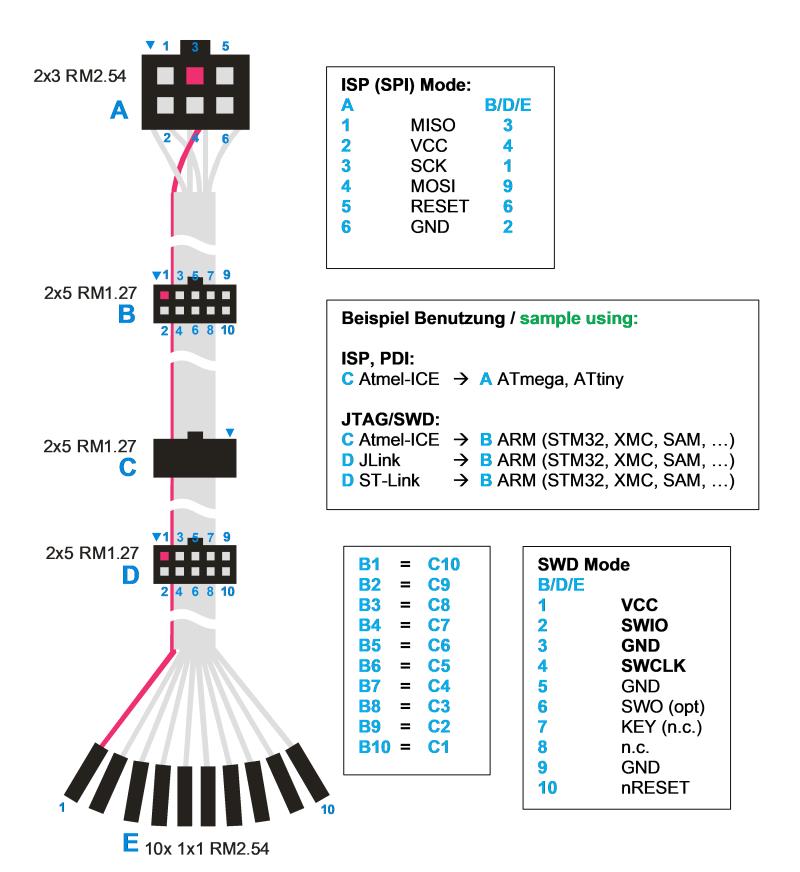
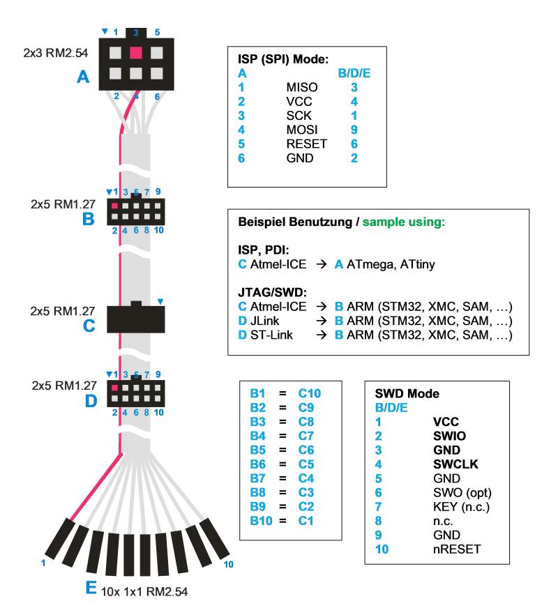
Pinbelegung ISP und SWD Adapter
2x3 RM2.54 A 1 MISO 3 2 VCC 4 3 SCK 1 4 MOSI 9 5 RESET 6 6 GND 2 2x5 RM1.27 B 1 3 5 7 9 2 4 6 8 10 Beispiel Benutzung / sample using: ISP, PDI: C Atmel-ICE -> ATmega, ATtiny JTAG/SWD: C Atmel-ICE -> B ARM (STM32, XMC, SAM, ...) D JLink -> B ARM (STM32, XMC, SAM, ...) D ST-Link -> B ARM (STM32, XMC, SAM, ...) 2x5 RM1.27 C 1 3 5 7 9 2 4 6 8 10 2x5 RM1.27 D 1 3 5 7 9 2 4 6 8 10 B1 = C10 B2 = C9 B3 = C8 B4 = C7 B5 = C6 B6 = C5 B7 = C4 B8 = C3 B9 = C2 B10 = C1 SWD Mode B/D/E 1 VCC 2 SWIO 3 GND 4 SWCLK 5 GND 6 SWO (opt) 7 KEY (n.c.) 8 n.c.
in „Atmel ICE Programmer und UPDI“ · Mikrocontroller und Digitale Elektronik · · Diagramme
-
PDF
MINI_STM32-V3.0_SCH.pdf
1 2 3 4 5V P1 U1 1 2 PA8 3 4 PA9 KEY1 PA0 14 PA0/WKUP/USART2_CTS/ADC12_IN0/TIM2_CH1_ETR PC0/ADC12_IN10 8 PC0 DB00 PA10 5 6 PA11 KEY2 PA1 15 PA1/USART2_RTS/ADC12_IN1_TIM2_CH2 PC1/ADC12_IN11 9 PC1 DB01 C20 Y3 C21 PA12 7 8 PA13
in „ISP Bootloader über USART bei STM32 funktioniert nicht“ · Mikrocontroller und Digitale Elektronik ·
-
Datei
cj_gol.c
stdint.h> #include <string.h> #include <ctype.h> // Special Libs #include "defines.h" #include "tm_stm32f4_delay.h" #include "tm_stm32f4_ili9341_ltdc.h" #include "tm_stm32f4_fonts.h" #include "tm_stm32f4_rng.h" // Projekt Header #include "cj_gol.h" ///////////////////////////////////////////// // Conways
in „Bedarf an eigenbau STM32F429 Evaluation Board ?“ · Mikrocontroller und Digitale Elektronik ·
-
Datei
main.c
#include "stm32f2xx.h" #include "stm32_eval.h" void DMA_Config(void); void UART_vINIT(void); void NVIC_Configuration(void); uint16_t USART_Buffer_Tx[2]; uint16_t USART_Buffer_Rx[2]; void DMA1_Stream1_IRQHandler(void
in „STM32F207: USART + DMA“ · Mikrocontroller und Digitale Elektronik ·
-
 Bild
Bild
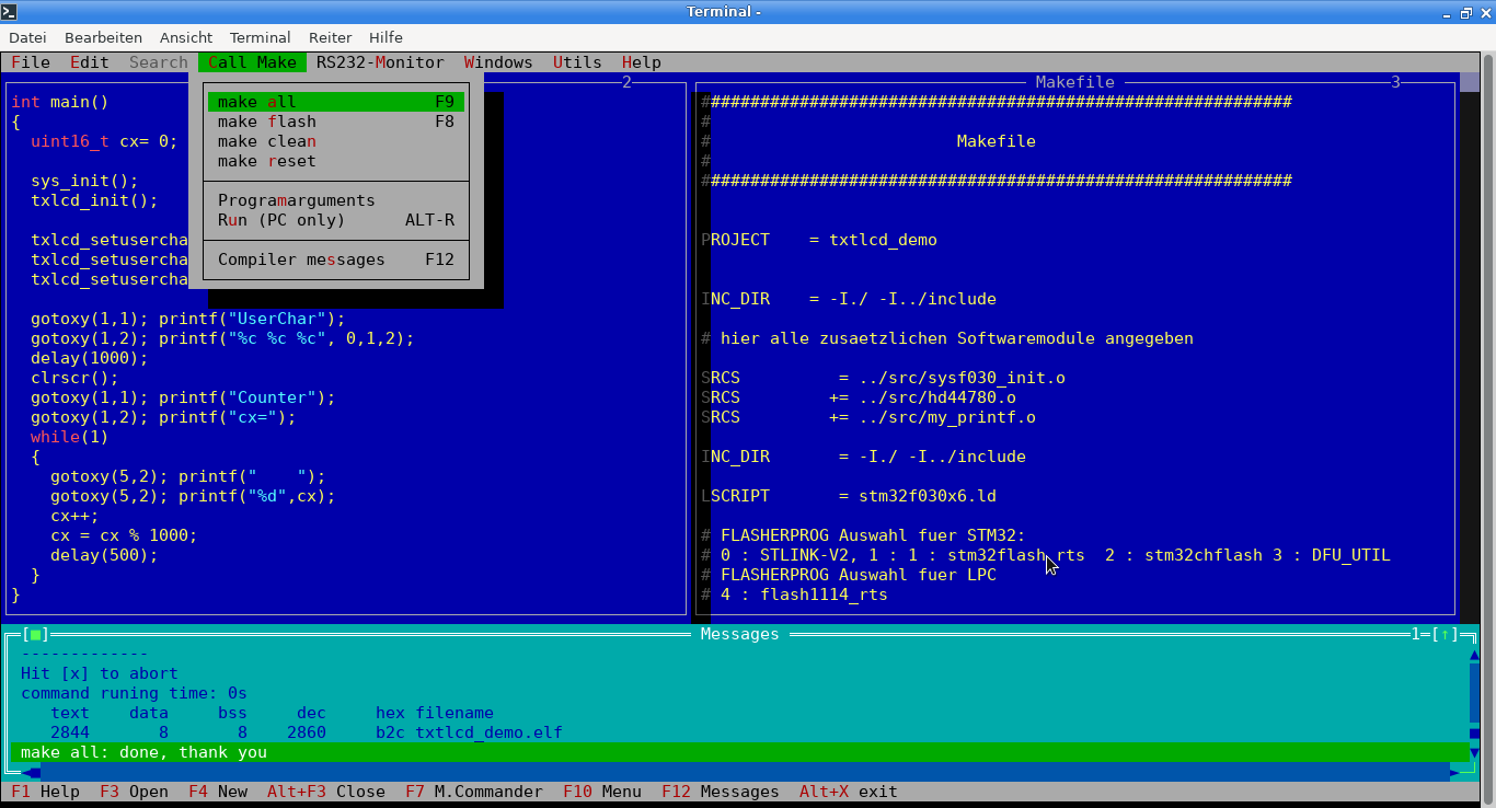
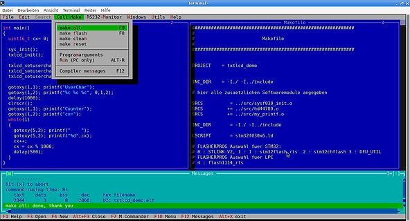
Terminal-Fenster mit C-Code und Makefile
../include SRCS = ./src/sysf03_init.o SRCS += ./src/my_printf.o INC_DIR = -I/-I../include SCRIPT = stm32f030x6.ld FLASHERPROG Auswahl fuer STM32: 0 : STLINK-V2, 1 : 1 : stm32flash 2 : stm32chflash 3 : DFU_UTIL 4 : flash1114_rts Hit [x] to abort command running time: 0s text data bss dec hex filename 2844 8 8 2860 b2c txtlcd demo.elf make all: done, thank you
in „Live-Linux: Anleitung schreiben“ · PC Hard- und Software · · Screenshots
-
 Bild
Bild
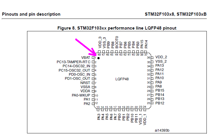
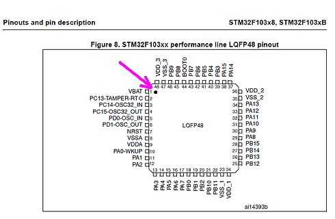
Pinbelegung STM32F103xx LQFP48 Mikrocontroller
Pinouts and pin description STM32F103x8, STM32F103xB Figure 8. STM32F103xx performance line LQFP48 pinout VBAT 1 PC13-TAMPER-RTC 2 PC15-OSC32_OUT 3 PD1-OSC_OUT 4 NRST 7 VSSA 8 VDDA 9 PA0-WKUP 10 PA1 11 PA2 12 PA3 13 PA4 14 PA5 15 PA6 16 PA7 17 PB0 18 PB1 19 PB2 20 PB10 21 PB11 22 VSS_1 23 VDD_1 24 PB12 25 PB13 26 PB14 27 PA8 28 PB15 29 PA9 30 PA10 31 PA11 32 PA12 33 PA13 34 VSS_2 35 VDD_2 36 PA14 37 PB3 38 PB4 39 PB5 40 PB7 41 PB8 42 BOOT0 43 VSS_3 44 VDD_3 45 46 47 48 LQFP48 ai14393b
in „STM32F103C6T6A Lässt sich nicht programmieren“ · Mikrocontroller und Digitale Elektronik · · Screenshots
-
Datei
max7219.c
Treibers Autor : Christian Julius 12.2015 ******************************************** */ #include "stm32f4xx.h" #include "stm32f4xx_spi.h" #include "stm32f4xx_rcc.h" #include "stm32f4xx_gpio.h" /* -------------- Standard Include Files ----------------- */ #include <stdio.h> #include <stdint.h> #include
in „Codearchiv: STM32F4xx MAX7219 7-Segment Ansteuerung“ · Projekte & Code ·
-
Datei
max7219.c
Treibers Autor : Christian Julius 12.2015 ******************************************** */ #include "stm32f4xx.h" #include "stm32f4xx_spi.h" #include "stm32f4xx_rcc.h" #include "stm32f4xx_gpio.h" /* -------------- Standard Include Files ----------------- */ #include <stdio.h> #include <stdint.h> #include
in „Organisation der Header und Includes“ · Mikrocontroller und Digitale Elektronik ·
-
Datei
max7219.c
Treibers Autor : Christian Julius 12.2015 ******************************************** */ #include "stm32f4xx.h" #include "stm32f4xx_spi.h" #include "stm32f4xx_rcc.h" #include "stm32f4xx_gpio.h" /* -------------- Standard Include Files ----------------- */ #include <stdio.h> #include <stdint.h> #include
in „NRF24L01: Handauflegen hilft?“ · Mikrocontroller und Digitale Elektronik ·
-
Datei
stm32f4xx_spi.h
SPI_Direction_Tx)) /** * @} */ /** @defgroup SPI_I2S_interrupts_definition * @{ */ #define SPI_I2S_IT_TXE ((uint8_t)0x71) #define SPI_I2S_IT_RXNE ((uint8_t)0x60) #define SPI_I2S_IT_ERR ((uint8_t)0x50) #define I2S_IT_UDR ((uint8_t)0x53) #define SPI_I2S_IT_TIFRFE ((uint8_t)0x58) #define IS_SPI_I2S_CONFIG_IT(IT) ((
in „STM32F4XX SPI Slave“ · Mikrocontroller und Digitale Elektronik ·
-
Datei
bitbang_spi.h
14 #define bb_mosi_port B #define bb_mosi_pin 15/**/ #endif #if bb_port==7 #define bb_sck_port B//stm-spi3 #define bb_sck_pin 3 #define bb_miso_port B #define bb_miso_pin 4 #define bb_mosi_port B #define bb_mosi_pin 5/**/ #endif #if bb_port==8 #define bb_sck_port C//stm sdio #define bb_sck_pin 12 #define
in „LPC1758 und PN532 über SPI“ · Mikrocontroller und Digitale Elektronik ·
-
Datei
irmp.h
) # elif defined (ARM_STM32F10X) # define IRMP_PORT_RCC CONCAT(RCC_APB2Periph_GPIO, IRMP_PORT_LETTER) # elif defined (ARM_STM32F4XX) # define IRMP_PORT_RCC CONCAT(RCC_AHB1Periph_GPIO, IRMP_PORT_LETTER) # endif # define IRMP_BIT
in „IRMP - Infrared Multi Protocol Decoder“ · Projekte & Code ·
-
Datei
USART_Print.c
#include "stm32f10x.h" #include "stm32f10x_gpio.h" #include "stm32f10x_rcc.h" #include "stm32f10x_usart.h" #include <stdio.h> /***************************************************************************//** * Declare
in „USART --- UART“ · Mikrocontroller und Digitale Elektronik ·
-
PDF
Atollic_Develop_Debug_BootloaderApps_ARMCortex.pdf
STM32F4-Discovery • STM32F4_Discovery_Bootloader_APP • STM32F4_Discovery_Bootloader_BL BL = Bootloader. APP = Application. Both must be downloaded. 2016-04-20 6 Memory map • Bootloader and application
in „GDB - ARM, Debug mit Offset“ · Mikrocontroller und Digitale Elektronik ·
-
Datei
ARM-STM32F4-Serie-Daten.txt
Anzahl der Timer/Zähler: 14 Timer Prozessor-Serie: ARM Cortex-M Art des Programmspeichers: Flash Serie: STM32F4 STM32F407VGT6 ============= ARM Mikrocontroller - MCU ARM M4 1024 FLASH 168 Mhz 192kB SRAM Kern: ARM Cortex M4 Datenbus-Weite: 32 bit Maximale Taktfrequenz: 168 MHz Programmspeichergröße: 1024 kB
in „STM32F407VGT6 Pinkompatibilität zu den F427/F437 Typen ?“ · Mikrocontroller und Digitale Elektronik ·
-
 Bild
Bild
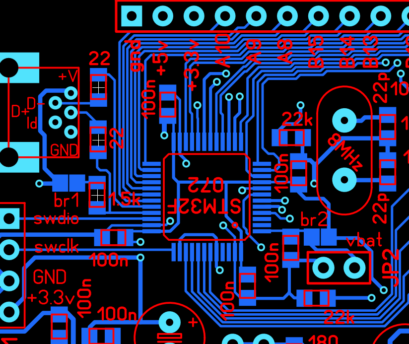
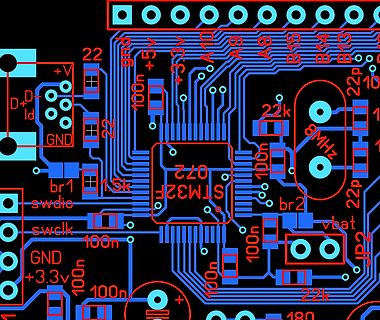
PCB-Layout eines STM32-Mikrocontrollers
+V, D+, Id, GND, 22, 100n, +3.3V, br1, swdio, swclk, 1.5k, STM32F, 072, br2, 100n, 8MHz, 22p, 22k, vbat, JP2, 100n, 22k, 180, 100n, +3.3V, GND
in „USB Problem bei STM32F072C8“ · Mikrocontroller und Digitale Elektronik · · Layouts
-
Datei
stm32f103r8_rom.ld
/* Linker script for lm3s6730 * * Version:Sourcery G++ 4.2-62 * BugURL:https://support.codesourcery.com/GNUToolchain/ * * Copyright 2007 CodeSourcery. * * The authors hereby grant permission to use, copy, modify, distribute, * and license this software and its documentation for any purpose, provided * that existing copyright notices are retained in all copies and that this * notice is included verbatim in any distributions. No written agreement, * license, or royalty fee is required for any of the authorized uses. * Modifications to this software may be copyrighted by their authors * and need
in „Bibliotheken nur teilweise Linken“ · Mikrocontroller und Digitale Elektronik ·
-
Datei
stm32f103c8_flash.ld
--------------------------------------------- * Linker script for running in internal FLASH on the STM32F103C8 *----------------------------------------------------------------------------*/ OUTPUT_FORMAT("elf32-littlearm", "elf32-littlearm", "elf32-littlearm") OUTPUT_ARCH(arm) SEARCH_DIR(.) /* Memory
in „uint64_t auf STM32F103“ · Mikrocontroller und Digitale Elektronik ·
-
Datei
u8g_com_arm_stm32.c
/** \author Wojciech Domski */ #include "u8g_com_arm_stm32.h" #include "hw_config.h" uint8_t control = 0; void u8g_Delay(uint16_t val) { HAL_Delay(val); } void u8g_xMicroDelay(uint16_t val) { static uint32_t i, j; static uint32_t freq; freq =
in „STM32 F103 - I2C Probleme“ · Mikrocontroller und Digitale Elektronik ·
-
Datei
STM32F334K8_FLASH.ld
/* ***************************************************************************** ** ** File : stm32_flash.ld ** ** Abstract : Linker script for STM32F334K8 Device with ** 64KByte FLASH, 12KByte RAM ** ** Set heap size, stack size and stack location according ** to application requirements. ** ** Set memory bank area and size if external memory is used. ** ** Target : STMicroelectronics STM32 ** ** Environment : Atollic TrueSTUDIO(R) ** ** Distribution: The file is distributed as is, without any warranty ** of any kind. ** ** (c)Copyright Atollic AB. ** You may use this file as-is or modify
in „CCMRAM richtig einsetzen“ · Mikrocontroller und Digitale Elektronik ·
-
PDF
penhub.pdf
15 RTC-C 1 T2.2 T5.2PA1 TEMP R25 LTN 10 T 0 X1:2 PC2 ADC.3 36 ESYN N 1 X1:1 15k RTCREF T1.3N T15.2 T8.3PB15 C8 C7 C27 5 k 2u2 10n 10n 4 5 R 1 12 VSSA D1 STM32L496 +3.3V D5 NOR-Flash +3.3V 9 WPROT 1 HOLD/DNU 16 SCK Q 8 1 1 2 2 2 15 C17 C16 C20 C18 7 D D12 D11 D10 D9 D5 CS +5V V+ 100n 7 8 100n 0 100n 0
in „Datenlogger Pendeluhr“ · Mikrocontroller und Digitale Elektronik ·
-
PDF
FK723M1-ZGT6.zh-CN.en.pdf
PD5 119 PD5 Trigger MCU reset when power is turned on or SW2 is pressed PD6 122 PD6 RST PD7 123 PD8 77 PD7 C PD9 78 PD8 C PD10 79 PD9 T1 PD10 R2 8050 SW2 PD11 80 PD11 C1 PD12 81 PD12 10K 0.1uF PD13 82 PD13 PD14 85 PD14 R3 C3 PD15 86 10K PD15 0.1uF STM32H723ZE/G GND In normal state, the two transistors
in „Neues Blackboard mit STM32H723“ · Mikrocontroller und Digitale Elektronik ·
-
Datei
stm32_ub_i2c1.c
Funktion : I2C-LoLevel-Funktionen (I2C-1) // // Hinweis : mögliche Pinbelegungen // I2C1 : SCL :[PB6, PB8] // SDA :[PB7, PB9] // externe PullUp-Widerstände an SCL+SDA notwendig //-------------------------------------------------------------- // Edited: 15.04.2015 // CPU STM32F10x // CoIDE 1.7.8 // GCC 4_
in „STM32F105 bei I2C Read ein Byte zu viel“ · Mikrocontroller und Digitale Elektronik ·
-
Datei
main.h
#ifndef __MAIN_H_ #define __MAIN_H_ #include <libopencm3/stm32/rcc.h> #include <libopencm3/stm32/gpio.h> #include <libopencm3/stm32/i2c.h> #include <libopencm3/stm32/exti.h> #include <libopencm3/cm3/systick.h> #include <libopencm3/cm3/nvic.h> #include <stdint.h
in „STM32F0 EXTI“ · Mikrocontroller und Digitale Elektronik ·
-
Datei
eeprom.c
I2C_EVENT_MASTER_RECEIVER_MODE_SELECTED) != SUCCESS) return ERROR; /* Wichtiger Hinweis, bzgl der Reihenfolge des Bit Setzens, Manual. STM32F407, S834 Die Konfiguration muss VOR dem Buszugriff erfolgen, d.h. das Datenbyte wird erst ganz zum Schluss ausgelesen */ uint8_t foo; for (uint16_t i = 0; i < (nrBytes-1); i++) { foo = I2C_ReceiveData
in „Lebensdauer von lokalen Variablen“ · Softwareentwicklung ·
-
Datei
sccb.c
I2C_InitStructure; // Code from: http://www.urel.feec.vutbr.cz/MPOA/2014/cam-ov7670 // https://github.com/g4lvanix/STM32F4-examples/blob/master/I2C%20Master/main.c // and: https://github.com/erikandre/stm32-ov7670 -> stm32-ov7670/src/OV7670_control.c void I2C_Config() { // enable APB1 peripheral clock for I2C1 RCC_APB1PeriphClockCmd
in „OV7670 blockiert Bus nach senden des Registers“ · Mikrocontroller und Digitale Elektronik ·
-
PDF
Cactus_NeuroStim_Eval_Board_EB1CSI021_Datasheet.pdf
Neurostimulation / NeuroModulation Applications • Contains Two Synchronizable CSI021 ICs • Onboard Low-Power 8-bit MCU (STM- 8L151G6) With Preloaded Firmware to Program CSI021 • ST-Link V2 Dongle Provided to Communicate and Program the MCU for Customization • Onboard Adjustable Power Management APPLICATIONS Circuitry
in „Cactus Semiconductor EB1CSI021“ · Mikrocontroller und Digitale Elektronik ·
-
Datei
startup_stm32f10x_hd.c
IRQHandler(void); void WEAK RTCAlarm_IRQHandler(void); void WEAK USBWakeUp_IRQHandler(void); void WEAK TIM8_BRK_IRQHandler(void); void WEAK TIM8_UP_IRQHandler(void); void WEAK TIM8_TRG_COM_IRQHandler(void); void WEAK TIM8_CC_IRQHandler(void); void WEAK ADC3_IRQHandler(void); void WEAK FSMC_IRQHandler(void)
in „STM32F10x mit Eclipse, yagarto (GCC) und J-Link (GDB)“ · Mikrocontroller und Digitale Elektronik ·
-
 Bild
Bild
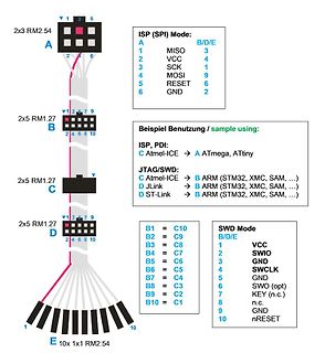
Pinbelegung ISP und SWD Adapter
2x3 RM2.54 A 1 MISO 3 2 VCC 4 3 SCK 1 4 MOSI 9 5 RESET 6 6 GND 2 2x5 RM1.27 B 1 3 5 7 9 2 4 6 8 10 Beispiel Benutzung / sample using: ISP, PDI: C Atmel-ICE -> ATmega, ATtiny JTAG/SWD: C Atmel-ICE -> B ARM (STM32, XMC, SAM, ...) D JLink -> B ARM (STM32, XMC, SAM, ...) D ST-Link -> B ARM (STM32, XMC, SAM, ...) 2x5 RM1.27 C 2x5 RM1.27 D B1 = C10 B2 = C9 B3 = C8 B4 = C7 B5 = C6 B6 = C5 B7 = C4 B8 = C3 B9 = C2 B10 = C1 SWD Mode B/D/E 1 VCC 2 SWIO 3 GND 4 SWCLK 5 GND 6 SWO (opt) 7 KEY (n.c.) 8 n.c. 9 GND 10 nRESET 10x 1x1 RM2.54 E
in „Atmel ICE Programmer und UPDI“ · Mikrocontroller und Digitale Elektronik · · Diagramme
-
Datei
usart.c
#include "stm32f0xx.h" #include "stm32f0xx_rcc.h" #include "stm32f0xx_gpio.h" #include "stm32f0xx_usart.h" inline void delay_ms(uint32_t dtime) { volatile uint32_t n = (dtime * 3750); while(n > 0) n--; } void serial_init
in „STM32F030F4P6 und USART1“ · Mikrocontroller und Digitale Elektronik ·
-
Datei
stm32f2xx_rcc.h
RCC_HCLK_Div16)) /** * @} */ /** @defgroup RCC_Interrupt_Source * @{ */ #define RCC_IT_LSIRDY ((uint8_t)0x01) #define RCC_IT_LSERDY ((uint8_t)0x02) #define RCC_IT_HSIRDY ((uint8_t)0x04) #define RCC_IT_HSERDY ((uint8_t)0x08) #define RCC_IT_PLLRDY ((uint8_t)0x10) #define RCC_IT_PLLI2SRDY ((uint8_t)0x20
in „STM32F2xx USART weigert sich“ · Mikrocontroller und Digitale Elektronik ·
-
Datei
serialAccelerometer.ino
// read accelaration sensor and print serial // TX pin is PD8 // STM32F4 Discovery // accelerometer: LIS203DL ( included in STM32F4, some boards may have the LIS3DSH ) // example from http://stm32duino.com/viewtopic.php?t=282 /* // serial interfaces // the serial
in „STM32F4 Discovery Arduino“ · Mikrocontroller und Digitale Elektronik ·
-
Datei
CRC.o.lst
1 "../CRC.cpp" 1:../CRC.cpp **** 2:../CRC.cpp **** #include "CRC.hpp" 3:../CRC.cpp **** #include <stm32f4xx_crc.h> 4:../CRC.cpp **** #include "Constants.hpp" 5:../CRC.cpp **** #include "App.hpp" 6:../CRC.cpp **** 7:../CRC.cpp **** 8:../CRC.cpp **** 9:../CRC.cpp **** TZApp::CCrc Crc; 10:../CRC.cpp **
in „Problem mit GCC-Optimierung“ · Mikrocontroller und Digitale Elektronik ·
-
Datei
blinky_bluepill.ino
/* STM32 BluePill blinky Funktioniert mit einem unveränderten BluePill und ST-Link Programmierung. Auf den Pins PA0 bis PA12, PA15 und PB0 bis PB1, PB3 bis PB15 und PC13 bis PC15. Nur PB13 hat noch Einschränkungen. Vorraussetzung ist Arduino 1.8.5 in Voreinstellung eingetragen: https://github.com/stm32duino/BoardManagerFiles/raw/master/STM32/package_stm_index.json und mit dem Boardverwalter (Boardmanager) dann dazugeladen: STM32 Cores by ST-Microelektronics
in „stm32f103-bluepill-peripherie“ · Mikrocontroller und Digitale Elektronik ·
-
Datei
gdbswim_stlink.ini
loaded by STVD for SWIM # COPYRIGHT STMicroelectronics (c) 2002-2008, all rights reserved # VERSION STM8 V4.1.0 gdb.ini for SWIM # # # emulator reset port # define emulator-reset-port target gdi -dll swim\stm_swim.dll -stlink3 -port $arg0 end # # emulator reset port and MCU # define emulator-reset-port-mcu target gdi -dll swim\stm_swim.dll -stlink3 -port $arg0 -mcuname $arg1 mcuname -set $arg1 end # # emulator reset port with hot plug connection # define emulator-reset-hotplug-port target gdi -dll swim\stm_swim.dll -stlink3 -
in „GDB Experten gesucht für Eclipse integration“ · Mikrocontroller und Digitale Elektronik ·
-
Datei
HWMonitor.txt
LDT3 [ ] UCFG _CRS PICM APIC _PRT HUB0 _ADR _STA PICM APIC _PRT _PRW SAT1 _ADR PRI0 _ADR SPTM _GTM _STM MAST _ADR _GTF SEC0 _ADR SSTM _GTM _STM MAST _ADR _GTF DRMP SAT2 _ADR PRI0 _ADR SPTM _GTM _STM MAST _ADR _GTF SEC0 _ADR SSTM _GTM _STM MAST _ADR _GTF DRMP IDE0 _ADR A090 [ ] ID20 [ ] IDTS IDTP ID22 UMSS UMSP IDEP IDES GTM_ U2T_ T2U_ T2D_ STM_ GTF_ PRI0 _ADR _GTM _STM MAST _ADR _GTF SLAV _ADR _GTF SEC0 _ADR _GTM _STM MAST _ADR _GTF SLAV _ADR _GTF DRMP IGPU _ADR GPUR XVR0 _ADR PCV0 _PRW XVR1 _ADR PCV1 _PRW XVR2 _ADR PCV2 _PRW SMB0 _ADR SMCF
in „CPU Temperatursensor defekt => Absturz“ · PC Hard- und Software ·
-
Datei
adc.h
#ifndef STM32F1_ADC_H_ #define STM32F1_ADC_H_ /* ########################################################################################################################################################## */ /*
in „STM32F103 und ADC DMA mehrere Kanäle“ · Mikrocontroller und Digitale Elektronik ·
-
Datei
usart_stm32f4xx.c
/* * usart_stm32f4xx.c * * USART/UART-Treiber * * $Date: 2019-03-24 09:25:14 +0100 (So, 24 Mrz 2019) $ * $Revision: 578 $ * * 15.05.2019 Nicolas */ #ifdef STM32F4XX #include "usart.h" #include "hw_config.h" #include
in „STM32: Sendepuffer für USART“ · Mikrocontroller und Digitale Elektronik ·
-
Datei
edm_adc_multiplex_stm32.c
* Created: 28.02.2014 * Author: Nicolas */ #include <stdio.h> #include "../../ioMapping.h" #ifdef STM32F10x #include "stm32f10x_adc.h" #include "stm32f10x_gpio.h" #include "stm32f10x_rcc.h" #include "stm32f10x_adc.h" #include "stm32f10x_dma.h" #include "misc.h" #elif defined(STM32F4xx) #error "only for STM32F10x implemented yet" #else #error "unknown MCU" #endif #define NCHANNEL 10 uint16_t ADC1ConvertedValues[NCHANNEL]; /* Alle GPIO-Ports, an denen benutzte ADC-Kanaele haengen, passend einstellen */
in „STM32: Suche Hilfe zu ADC“ · Mikrocontroller und Digitale Elektronik ·
-
Datei
main.c
------------------- // File : main.c // Datum : 09.09.2014 // Version : 1.0 // Autor : AJ // CPU : STM32F4 // IDE : CooCox CoIDE 1.7.0 // Module : CMSIS_BOOT, M4_CMSIS_CORE // Hinweis : Diese zwei Files muessen auf 8MHz stehen // "cmsis_boot/stm32f4xx.h" // "cmsis_boot/system_stm32f4xx.c" //---------
in „STM32F4 DISCOVERY und SainSmart 3.2″ Display“ · Mikrocontroller und Digitale Elektronik ·
-
Datei
HWMonitor.txt
PMIO PMDM PSIO PSDM SMIO SMDM SSIO SSDM MODP MODS SDE0 _ADR _GTM _STM DRV0 _ADR _GTF DRV1 _ADR _GTF SDE1 _ADR _GTM _STM DRV0 _ADR _GTF DRV1 _ADR _GTF PEX5 _ADR _STA _PRW PIC5 API5 _PRT PEX6 _ADR _STA _PRW PIC6 API6 _PRT PEX7 _ADR _STA _PRW PIC7 API7 _PRT HUB0 _ADR _STA
in „Gibt Festplatte langsam Geist auf?“ · PC Hard- und Software ·
-
 Bild
Bild
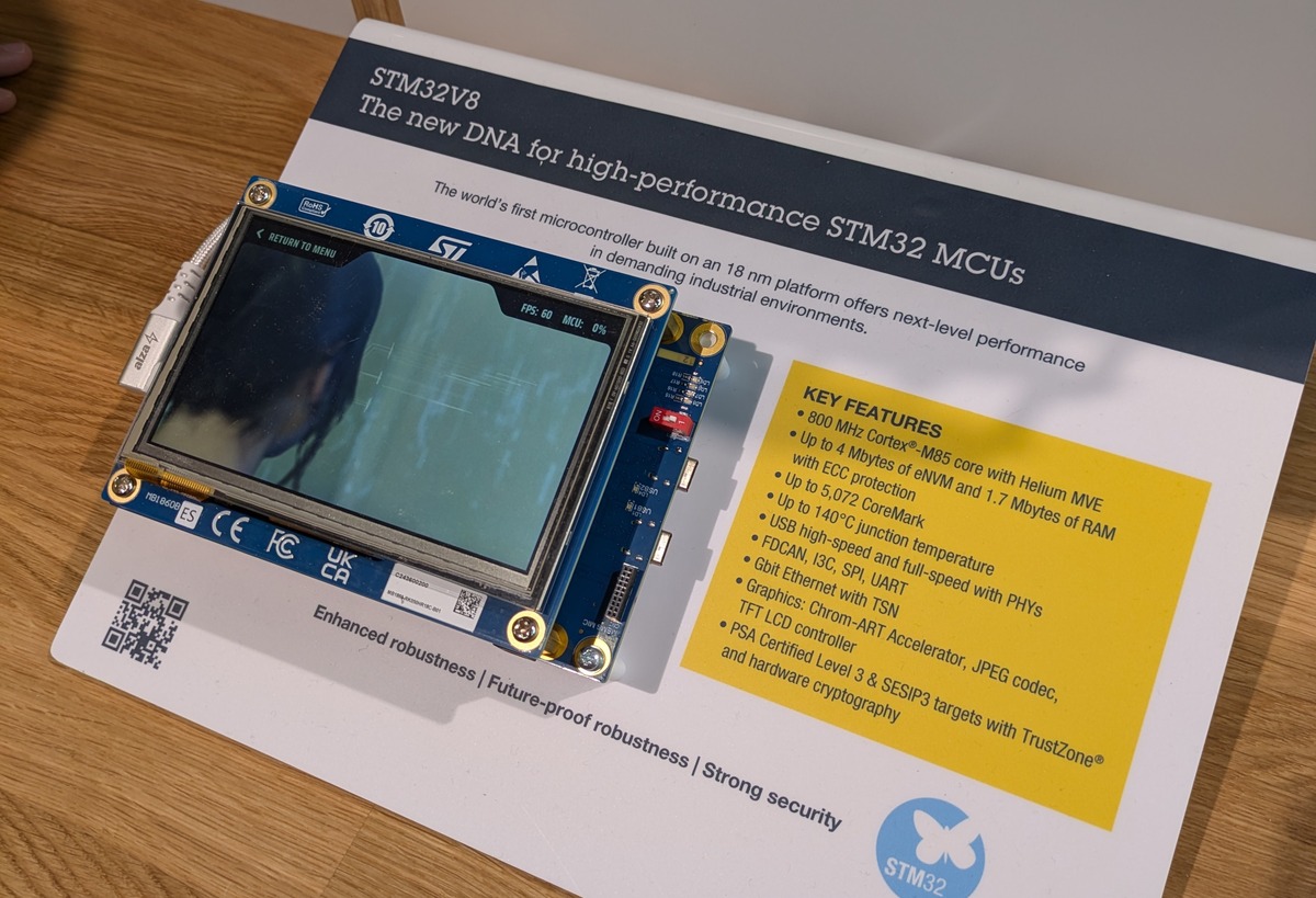
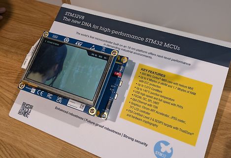
STM32V8 Mikrocontroller Display auf Informationsblatt
STM32V8 The new DNA for high-performance STM32 MCUs The world's first microcontroller built on an 18 nm platform offers next-level performance in demanding industrial environments KEY FEATURES 800 MHz Cortex-M85
in „EmbeddedWorld 2026, Tag 1 – AI fressen Elektronik auf“ · Mikrocontroller und Digitale Elektronik · · Fotos
-
PDF
rm0444-stm32g0x1-advanced-armbased-32bit-mcus-stmicroelectronics.pdf
disabled. . Table 7. SRAM size SRAM with parity enabled SRAM with parity disabled Device (Kbyte) (Kbyte) STM32G0B1xx and STM32G0C1xx 128 144 STM32G071xx and STM32G081xx 32 36 STM32G051xx and STM32G061xx 16 18 STM32G031xx and STM32G041xx 8 8 RM0444 Rev 5 65/1391 68 RM0444 The SRAM can be accessed by bytes,
in „Problem mit Clock Configuration beim STM32G031“ · Mikrocontroller und Digitale Elektronik ·
-
 Bild
Bild
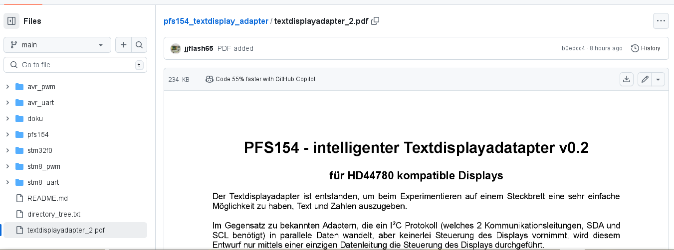
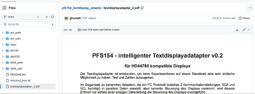
Screenshot einer Dateiansicht in einem Repository
Files pfs154_textdisplay_adapter / textdisplayadapter_2.pdf main + Q jjflash65 PDF added b0edcc4 8 hours ago History 234 KB Code 55% faster with GitHub Copilot avr_pwm avr_uart doku pfs154 stm32f0 stm8_pwm stm8_uart README.md directory_tree.txt textdisplayadapter_2.pdf PFS154 - intelligenter Textdisplayadapter
in „"Intelligenter" Textdisplayadapter mit Padauk PFS154“ · Projekte & Code · · Screenshots
-
Datei
stm32_eval_sdio_sd.c
SDIO_CmdInitTypeDef SDIO_CmdInitStructure; SDIO_DataInitTypeDef SDIO_DataInitStructure; /** * @} */ /** @defgroup STM32_EVAL_SDIO_SD_Private_Function_Prototypes * @{ */ static SD_Error CmdError(void); static SD_Error CmdResp1Error(uint8_t cmd); static SD_Error CmdResp7Error(void); static SD_Error CmdResp3Error(void
in „STM3210E EVAL SD-Controller SDIO + HiTOP“ · Mikrocontroller und Digitale Elektronik ·
-
Datei
simple.s
of range" .endif @ PLL output divider DIVP (allowed values: 2, 4, 6, or 8) @ DIVP must be chosen so that f_VCO falls in the range 192 - 432 MHz .set DIVP, 2 .if DIVP != 2 && DIVP != 4 && DIVP != 6 && DIVP != 8 .error "DIVP out of range" .endif @ VCO frequency (allowed range
in „STM32CubeIDE Debug View, Threads, Breakpoints“ · Mikrocontroller und Digitale Elektronik ·
-
Datei
versuche_int.c
/* ------------------------------------------------------- versuche_int.c Versuche zum STM8. zur Fehlersuche ohne jegliche Einbindung eines Softwaremoduls oder einer Headerdatei. Hier : Timer- und Interruptprogrammierung MCU : STM8S103F3 28.06.2016 R. Seelig ------------------------------
in „STM8S - Systemclock und Timer“ · Mikrocontroller und Digitale Elektronik ·
-
Datei
main.c
-----------------*/ /** * @brief Main program * @param None * @retval None */ int main(void) { uint8_t lcd_status = LCD_OK; CPU_CACHE_ENABLE(); /* STM32F7xx HAL library initialization: - Configure the Flash prefetch, instruction and Data caches - Configure the Systick to generate an interrupt each 1
in „Discovery_STM32F746 Linking Problem“ · Mikrocontroller und Digitale Elektronik ·
-
Datei
irsnd.c
---------------- */ void irsnd_init (void) { #ifndef ANALYZE # if defined(PIC_C18) // PIC C18 or XC8 compiler # if ! defined(__12F1840) // only C18: OpenTimer; # endif irsnd_set_freq (IRSND_FREQ_36_KHZ); // default frequency IRSND_PIN = 0; // set IO to outout PWMoff(); # elif defined (ARM_STM32) //
in „IRMP - Infrared Multi Protocol Decoder“ · Projekte & Code ·
-
Datei
irsnd.c
---------------- */ void irsnd_init (void) { #ifndef ANALYZE # if defined(PIC_C18) // PIC C18 or XC8 compiler # if ! defined(__12F1840) // only C18: OpenTimer; # endif irsnd_set_freq (IRSND_FREQ_36_KHZ); // default frequency IRSND_PIN = 0; // set IO to outout PWMoff(); # elif defined (ARM_STM32) //
in „IRMP - Infrared Multi Protocol Decoder“ · Projekte & Code ·