-
Datei
main.c
// Atmega328p intern 1 Mhz #define F_CPU 1000000UL #include <avr/io.h> #include <util/delay.h> #include <avr/interrupt.h> // #include <avr/power.h> #include <avr/sleep.h> #include "rfm69.c" uint8_t array[MAX_ARRAYSIZE
in „Atmega328p in Sleep und mit Watchdog wecken“ · Mikrocontroller und Digitale Elektronik ·
-
PDF
pbwake.pdf
R2 PB3 10k 3 PB4 Microcontroller 1 ATTiny-13 RESET/PB5 ATTiny-25 ATTiny-45 C N ATTiny-85 C R 0 G (ATMega-328P different pinout) 1 4 GND GND J3 1 V DEBUG + GND Michael Buesch <m@bues.ch> Sheet: / D File: pbwake.sch D Title: pbwake Size: A4 Date: 2020-07-17 Rev: 1.0 KiCad E.D.A. kicad 5.1.6+dfsg1-1 Id:
in „Powerbank-Wecker für neue ANKER Powerbank“ · Analoge Elektronik und Schaltungstechnik ·
-
 Bild
Bild
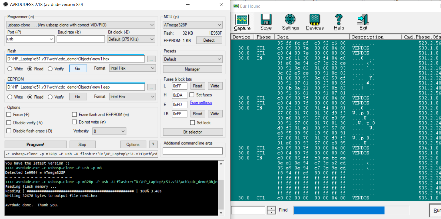
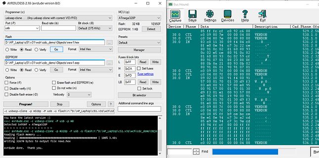
Software-Screenshot von AVRDUDE und Bus Hound
AVRDUDESS 2.18 (avrdude version 8.0) Programmer (c) usbasp-clone ... MCU (ATmega328P) Port (P) usb ... Baud rate (375 kHz) Flash 32 KB 1E950F EEPROM 1K Detect Bus Hound Capture Save Settings Devices Help Exit Device Data Description Cad Phase 30.0 CTL 85 ff c0 c9 02 cc 530.1 30.0
in „uC für 0,20€ CH552 / CH554 von WCH Billig Micro mit USB Funktion, Chip vorstellung“ · Mikrocontroller und Digitale Elektronik · · Screenshots
-
Datei
Main_c.txt
Define BAUD rate and F_CPU in #UART.h /* * Main.c * * Created: 06.12.2021 14:57:48 */ //controller: ATMEGA328P (same mikrocontroller as on Arduino UNO) #include <stdio.h> #include <avr/io.h> #include "UART.h" #include <util/delay.h> #include <avr/interrupt.h> #include <string.h> #include <util/twi.h> #include
in „Atmega328p + AS7261 I2C kein Ack vom slave“ · Mikrocontroller und Digitale Elektronik ·
-
PDF
Pinbelegung_Atmega.pdf
Atmega 328p / Pinbelegung Projekt ---------------- Stand: --------- Pin Port Funktion Erl. 1Funktion Erl. 2 Modul PIN 1 2 Header 1 PD3 OC2B Timer 2INT1 Hardw. 2 PD4 T0 Timer 0XCK UART 3 GND 4 VCC GND 5 6
in „Anschlussbelegung Atmega 328p TQFP-32 / MLF-32“ · Mikrocontroller und Digitale Elektronik ·
-
PDF
Pinbelegung_Atmega.pdf
Atmega 328p / Pinbelegung Projekt --------------- Stand: ------------ Pin Port Funktion Erl. 1Funktion Erl. 2 Modul PIN 1 2 Header 1 PD3 OC2B Timer 2INT1 Hardw.I. 2 PD4 T0 Timer 0XCK UART 3 GND 4 VCC 5 GND
in „Anschlussbelegung Atmega 328p TQFP-32 / MLF-32“ · Mikrocontroller und Digitale Elektronik ·
-
 Bild
Bild
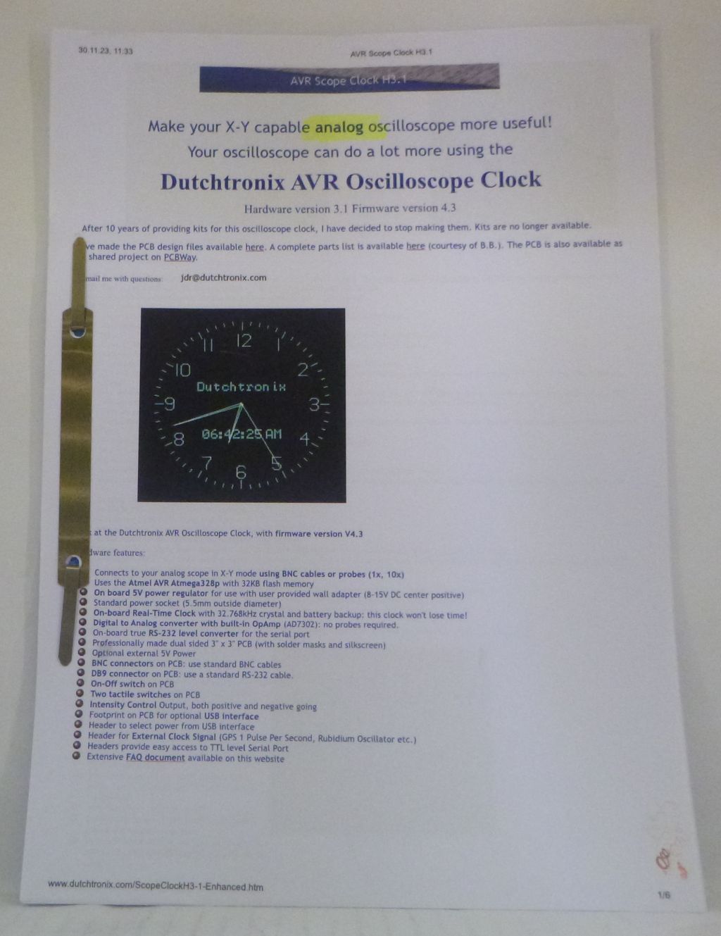
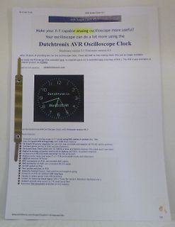
Webseite für DUTCHTRONIX AVR Oszilloskop-Uhr
dutchtronix.com Connects to your analog scope in X-Y mode using BNC cables or probes (1x, 10x) Use the Atmega328p with 236K flash memory Standard power regulator for your user provided wall adapter (8-15V DC center positive) On-board Real-Time Clock with 32.768kHz crystal and battery backup; clock won't lose
in „[V] Platine für Uhrenanzeige für analoge Oszilloskope“ · Markt · · Screenshots
-
PDF
nRF24L01plus.pdf
2.4GHz-HowTo von der Beschreibung abweichend sind die folgenden Verbindungen: • nRF24L01+ CE → Arduino D8 (ATMega8 PB0) • nRF24L01+ CSN → Arduino D4 (ATMega8 PD4) • nRF24L01+ IRQ → Arduino D3 (ATMega8 PD3) Gaaaanz wichtig der 100µF Kondensator nahe bei der 3,3V Versorgung für den nRF24L01+ nicht vergessen. Die
in „Repeating und Routing Netzwerk mit Arduino und nRF24L01+“ · Projekte & Code ·
-
Datei
ExternalTick.ino
AtomicSection ATOMIC_BLOCK(ATOMIC_RESTORESTATE) // http://ww1.microchip.com/downloads/en/DeviceDoc/ATmega48A-PA-88A-PA-168A-PA-328-P-DS-DS40002061A.pdf volatile uint16_t overflowCount; uint32_t getTicks() { union // AVR only hack { uint32_t ticks; struct { uint16_t lower; uint16_t upper; }; } t; AtomicSection
in „Arduino Interrupt Drehzahlmessung Faulhaber Motor“ · Mikrocontroller und Digitale Elektronik ·
-
PDF
nRF24L01_.pdf
2.4GHz-HowTo von der Beschreibung abweichend sind die folgenden Verbindungen: • nRF24L01+ CE → Arduino D8 (ATMega8 PB0) • nRF24L01+ CSN → Arduino D4 (ATMega8 PD4) • nRF24L01+ IRQ → Arduino D3 (ATMega8 PD3) Gaaaanz wichtig der 100µF Kondensator nahe bei der 3,3V Versorgung für den nRF24L01+ nicht vergessen. Die
in „Repeating und Routing Netzwerk mit Arduino und nRF24L01+“ · Projekte & Code ·
-
Datei
GraphicConsole2.txt
avr.device = atmega328p avr.clock = 16000000 avr.stack = 100 uart.baud = 115200 uart.Send.enable Dim x, y as integer Dim oldStr, newStr as string do print "§CG<"; print "§PC3<"; print "§PR200;90;500;99<"; print "§PC2<
in „Projekt: Virtuelle Instrumente an serielle Schnittstelle“ · Projekte & Code ·
-
 Bild
Bild
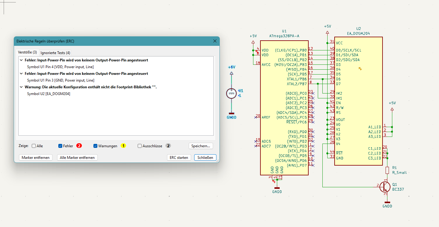
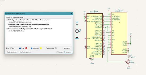
Schaltplan mit Fehlermeldung aus der ERC-Prüfung
Warnung: die aktuelle Konfiguration enthält nicht die Footprint Bibliothek. Symbol U2 [EA_DOGM204] U1 ATmega328PA-A U2 EA_DOGM204 VDD, VDD, AVCC, GND, GND, GNDD, +5V, +6V, +5V, 5V, 31, 39, 35, 36, 37, 34, 33, 32, 30, 29, 28, 27, 26, 25, 24, 23, 22, 21, 20, 19, 18, 17, 16, 15, 14, 13, 12, 11, 10, 9, 8, 7,
in „KiCAD 9.06: ERC mit unberechtigten Fehlern ?“ · Platinen · · Screenshots
-
PDF
Rollladensteuerung.pdf
Ports des Atmega16 angesteuert werden. Es wird der Stromlaufplan für beide AVR- Lösungen beigefügt, der Code ist ebenfalls für beide Lösungen generierbar. Zum Vergleich: Punkt Atmega168 Atmega16 HMI Über TWI angesteuert
-
 Bild
Bild
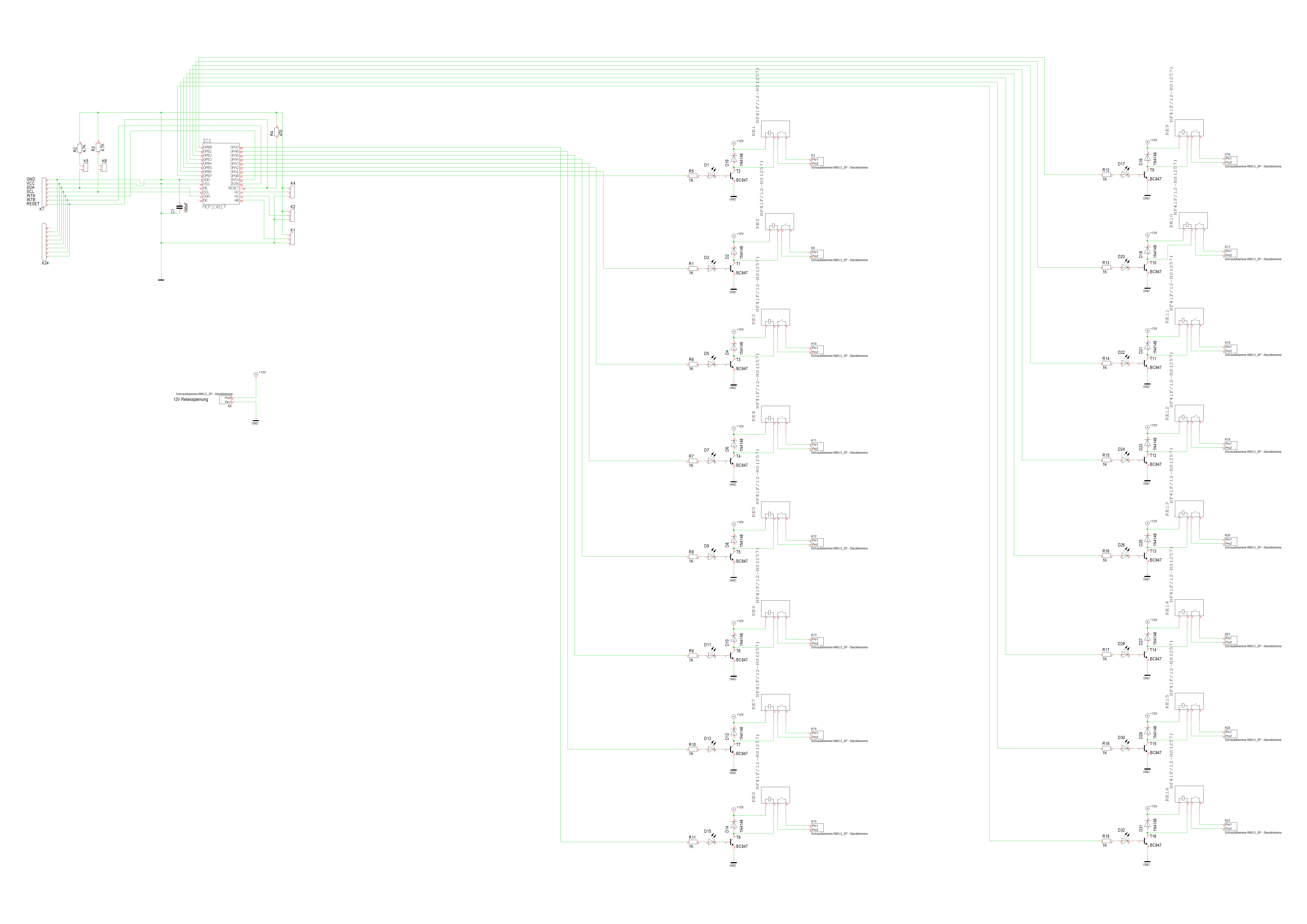
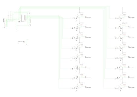
Schaltplan mit Mikrocontroller und mehreren Transistoren
ATMEGA328P, R1, R2, R3, R4, R5, R6, R7, R8, R9, R10, R11, R12, R13, R14, R15, R16, R17, R18, R19, R20, R21, R22, R23, R24, R25, R26, R27, R28, R29, R30, R31, R32, R33, R34, R35, R36, R37, R38, R39, R40, R41
in „MCP23017 und UDN2981A“ · Mikrocontroller und Digitale Elektronik · · Schaltpläne
-
 Bild
Bild
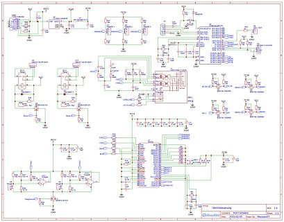
Schaltplan einer Mikrocontroller-Schaltung
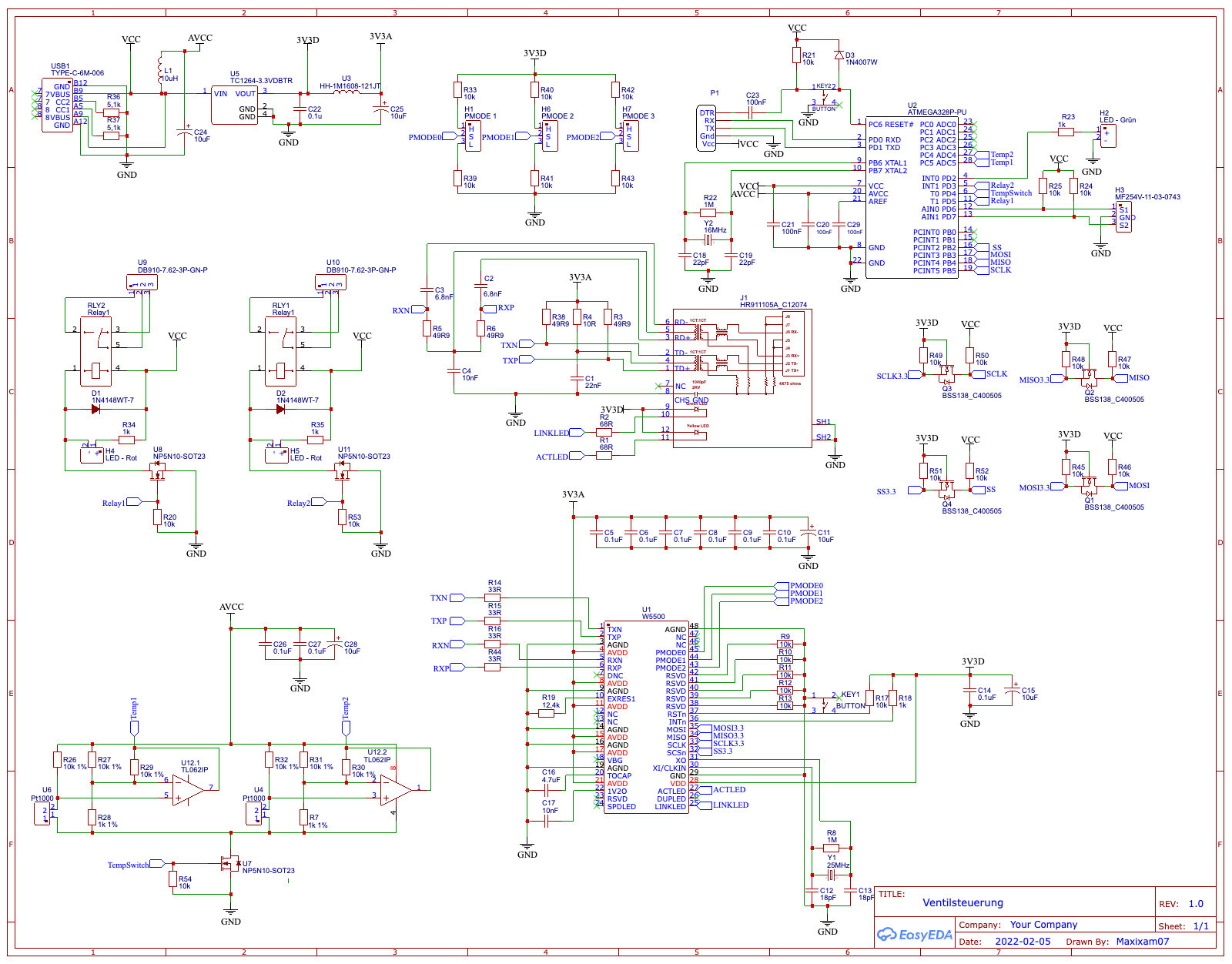
C4, 100nF, U1, TC126A, 3.3VDBTR, VOUT, C5, 100nF, 3V3D, 3V3A, R33, 10k, HTD1, MODE1, PMODE1, U2, ATMEGA328P-PU, VCC, GND, R23, 10k, R24, 10k, R25, 10k, R26, 10k, R27, 10k, R28, 10k, R29, 10k, R30, 10k, R31, 10k, R32, 10k, C23, 100nF, C22, 100nF, C21, 100nF, C20, 100nF, C19, 100nF, C18, 100nF, C17, 100nF
in „Funktioniert diese Atmega328 Schaltung?“ · Mikrocontroller und Digitale Elektronik · · Schaltpläne
-
PDF
AC_Board.pdf
GND/ANALOG DIGITAL_10(PWM) 16 Q I G 17 1K 8 DIGITAL_11(PWM) 18 GND DIGITAL_12 19 R8 DIGITAL_13 GND ATMEGA328-PU GND 3 R 8 4 D 4 5 Q E C t B e T D R5 G C LED1 330 V
in „GND Probleme beim Mosfet“ · Mikrocontroller und Digitale Elektronik ·
-
PDF
071148-D_CC2-AVR-board-2.pdf
einem natürlich der I C- beregister 4094 (siehe Bild 1). Statt ei- Aufgabe aber als schwierig. Man ATmega328 und erzeugt Code bis zu einer Größe von 4 KB. C-Compiler Eine 16-KB-Version kostet etwa 60 €, eine mit 32 KB ca. 75 €. Damit Für fortgeschrittene C-Programmierer wird die LCD-Ansteuerung über ist
in „Schaltung für Schrittmotor mit I2C“ · Mikrocontroller und Digitale Elektronik ·
-
PDF
RL-Extender.pdf
Rollladen-Extender Beschreibung Copyright (c) BBC-Hörer 2016-2018 - 18 - 12 Quellenangaben 1. AVR Atmega16, Atmel, Rev 2466T–AVR–07/10 2. AVR Atmega48-328, Atmel, Atmel8271J-AVR-Atmega-Datasheet_11/2015 3. AVR Atmega8515, Atmel, 2512K–AVR–01/10 4. AVR Codestyling, Atmel, AVR4027, Rev. 8453A-AVR-11/11
-
PDF
Inline_AVR8ASM_arduino.pdf
festgestellt werden, um welchen Port des µC es sich handelt. PIN 13 des Uno-Boards ist direkt mit PB5 des ATmega 328P verbunden, gehört also zum Port B des µC [Atmel Datenblatt 2009, Figure 2-1, S.5]. Alle Porteinstellungen sind in 8bit-Registern (8-bit Architektur, bit 0 bis 7) organisiert [Atmel Datenblatt
in „Mit dem ATMEL STUDIO 7 klarkommen“ · Mikrocontroller und Digitale Elektronik ·
-
PDF
assembler_arduino.pdf
festgestellt werden, um welchen Port des µC es sich handelt. PIN 13 des Uno-Boards ist direkt mit PB5 des ATmega 328P verbunden, gehört also zum Port B des µC [Atmel Datenblatt 2009, Figure 2-1, S.5]. Alle Porteinstellungen sind in 8bit-Registern (8-bit Architektur, bit 0 bis 7) organisiert [Atmel Datenblatt
in „Arduino Timerprobleme - suche programmierbaren Oszillator“ · Mikrocontroller und Digitale Elektronik ·
-
Datei
Bauelemente-Liste_v5_1_5.txt
Menge Bezeichnung Bezugsquelle Bestellnummer 1 LCD-Anzeigemodul 2x16 Zeichen Pollin 120 422 1 µC ATmega 328 Programmiert 1.04k 1 Low-Drop Festspannungsregler MCP1702 5V Reichelt MCP 1702-5002 1 Praezisionsspannungsquelle LM4040 2,5V Reichelt LM 4040 AIZ2,5 1 pnp-Transistor BC 557C Reichelt BC 557C 2
in „Info Platinen Bauteiletester / Transistortester“ · Markt ·
-
Datei
Bauelemente-Liste_v5_2_3.txt
Menge Bezeichnung Bezugsquelle Bestellnummer 1 LCD-Anzeigemodul 2x16 Zeichen Pollin 120 422 1 µC ATmega 328 Programmiert vers. 1.04k 1 Low-Drop Festspannungsregler MCP1702 5V Reichelt MCP 1702-5002 1 Praezisionsspannungsquelle LM336 2,5V Reichelt LM 336-Z2,5 1 pnp-Transistor BC 557C Reichelt BC 557C
in „Info Platinen Bauteiletester / Transistortester“ · Markt ·
-
Datei
UART.h
/* * uart.h * * UART example for ATMega328P clocked at 16 MHz * * TODO :- * - Implement string read function * - Optimize for size * - Add helper routines and compile to .a file * * Created on: 22-Jan-2014 * Author: Shrikant Giridhar */
in „expected declaration specifiers or '.' before '(' token“ · Mikrocontroller und Digitale Elektronik ·
-
Datei
Analog_Wandler.txt
Schaltung : //------------------------------------------------------------------------- // Prozessor : ATmega328P // Takt : 3686400 Hz // Sprache : C // Datum : 19.7.2017 // Version : 1.0 // Autor : Peter // Programmer: // Port : //------------------------------------------------------------------------- /
in „Fehler im Programm zum steuern von ATmega 328p Microcontroller“ · Mikrocontroller und Digitale Elektronik ·
-
Datei
adc.c
Schaltung : //------------------------------------------------------------------------- // Prozessor : ATmega328P // Takt : 3686400 Hz // Sprache : C // Datum : 19.7.2017 // Version : 1.0 // Autor : Peter // Programmer: // Port : //------------------------------------------------------------------------- /
in „Fehler im Programm zum steuern von ATmega 328p Microcontroller“ · Mikrocontroller und Digitale Elektronik ·
-
PDF
SMD_Thermometer.pdf
1206-D D16/D17 7 D18/D19/ SMD-LED_GELB 1206-D D20/D21 8 D22/D23/ SMD-LED_ROT 1206-D D24/D25 9 IC1 ATmega328P-PU DIL28 10 Sockel DIL28 11 PT100 PT100 MKDS1,5 12 9V Block Clip 13 K4 bis K13 Durchkontaktierung 14 R1 160 Ohm 0805 15 R2/R17/R20/ 1k 0805 R21/R24/R28/ R29 16 R3 1,5k 0805 17 R4 1,2k 0805 18 R5
in „Gibt es jemanden der mir ein Layout ertsellt?“ · Platinen ·
-
Datei
millisek_demo.c
----------- millisek_demo.c --------------------------- Demo fuer Zeitmessung Millisekunde MCU : ATmega48 .. ATmega328 10.08.2016 R. Seelig -------------------------------------------------------------------- */ #include <avr/io.h> #include <avr/pgmspace.h> #include <avr/interrupt.h> #include <stdarg.h
in „Arduino Zeitmessung mit externes Modul das ms messen kann?“ · Mikrocontroller und Digitale Elektronik ·
-
PDF
UpdateLoader___leo-andres.de_-_Wiki.pdf
altes UpdateLoader-Projekt 2.1 von 2009) 2.2.1.63 (11/2012): RC1 für 2.2.1: Neue Signaturen für ATmega328P, ATmega168P; UNC/UTF8-Pfade; Reset-Impuls auf der DTR-Leitung (kein Download) 2.2.1.72 (08/2013): Release 2.2.1: Neuer Programmpaket-Modus, Veröffentlichung der vorigen Änderungen 2.2.2.0 (11/2013
in „UpdateLoader: Benutzeroberfläche für FastBoot AVR-Bootloader“ · Projekte & Code ·
-
PDF
ttester-eps-converted-to.pdf
VCC VCC Ubat Reset 3 k 2 1 0 ATmega8/88/168/328 1 1 2 R 1 R 1 23 PC6(RESET) PC0(ADC0) TP1 C3 PC1(ADC1) 24 TP2 20 25 9V 100n AVCC PC2(ADC2) 26 TP3 PC3(ADC3) 21 27 2 0 4 0 6 0 AREF PC4(ADC4/SDA) 28 R 4 R 4 R 4 C1 1n PC5(ADC5/SCL) R12 22
-
Datei
uart.h
/* * Library to provide serial access on atmega328p and compatible parts. */ /* * Copyright 2015 Martyn Welch <martyn@welchs.me.uk> * All rights reserved. * * Redistribution and use in source and binary forms, with or without * modification, are
in „ATMEGA328 Led-Fader Projekt instabil“ · Mikrocontroller und Digitale Elektronik ·
-
Datei
CMakeLists.txt
BlinkExample NONE) # <-- Prjektname enable_language(C) SET(FILES main.c) # <-- Quelldatei(en) SET(DEVICE atmega328p) # <-- MCU SET(FREQ 16000000) # <-- MCU-Frequenz set(AVR_H_FUSE 0xDB) SET(AVRBIN /usr/bin) # <-- Toolchain SET(AVROBJCOPY avr-objcopy) # <-- "" SET(AVRSIZE avr-size) # <-- "" SET(AVRDUDE avrdude
in „No rule to make target CLion“ · Mikrocontroller und Digitale Elektronik ·
-
PDF
Client_1.pdf
3,3V 7805TV 3 1 1 5 VO VI L1 1 GND +5V K F 2 C3 + C5 7 n 4 0 100nF L2 C 1 0 1 1 1 R L3 GND ATMEGA328-20P JP3 1 PC6(/RESET/PCI14) (PCI8/ADC0)PC0 23 1 (PCI9/ADC1)PC1 24 2 L4 22 25 3 F 21 AGND (PCI10/ADC2)PC2 26 4 1 2 20 AREF (PCI11/ADC3)PC3 27 5 C 2 AVCC (PCI12/ADC4/SDA)PC4 (PCI13/ADC5/SCL)PC5 28
in „Größe einer char wird überschritten?“ · Mikrocontroller und Digitale Elektronik ·
-
 Bild
Bild
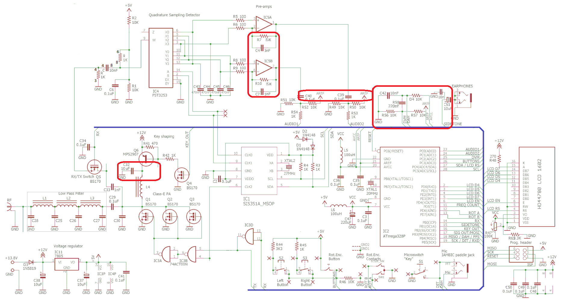
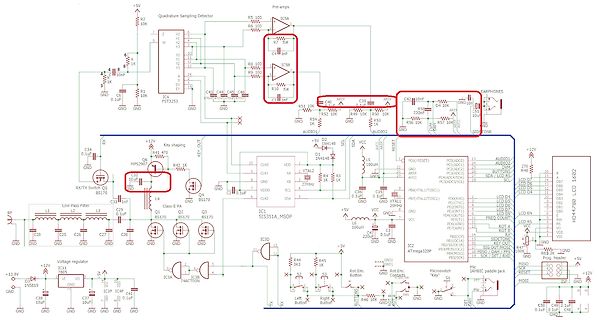
Schaltplan einer Audio-Schaltung mit Mikrocontroller
regulator, +13.8V, IC1 SI5351A MSOP, CLK0, CLK1, X2, XTAL2, 27MHz, VDD, VSS, VCLO, SCL, SDA, I2C, IC2 ATmega328P, RESET, VCC, GND, PB0 bis PB7, PC0 bis PC5, PD0 bis PD7, ADC0 bis ADC7, RESET, PORTB, PORTC, PORTD, LCD CS, LCD EN, LCD RS, LCD RW, LCD D0 bis D7, LCD D, LCD C, LCD B, LCD A, LCD R, LCD G, LCD
in „Alternativer SSB-TX Ansatz => QRP“ · HF, Funk und Felder · · Schaltpläne
-
PDF
ch32v003_getting_started.pdf
Ardudino UNO / nano oder eines AVR-Systems mit zugänglichen GPIO-Pins und einer USB2UART Bridge. ATmega328, ATmega168, ATmega8 und ATtiny2313 sind in der Lage, die Firmware in den Programmer zu flashen. Übersicht der Schritte zum Aufbau des Selbstbauprogrammers und „erste Schritte“ bei der Programmierung
in „CH32V003: Selbstbauprogrammer und "Getting started"“ · Projekte & Code ·
-
Datei
main.c
/* * ATMEGA328_clockgen.c * * Created: 02.01.2022 02:58:26 * Author : tboes Generate clock on PB0 / D8 */ #include <avr/io.h> #include <util/delay.h> void resetstring(void); void sendpulse(void); void sendcmd(
-
Datei
ADC_Trigger.c
/* Testprogramm für Timer-triggert-ADC * Hardware: Arduino Uno (ATMega328p) * + Olimex Proto-shield für LEDs * Compiler AVR-GCC 4.9.2 * Stand 13.06.2017 / AG */ #define F_CPU 16000000UL #include <avr/io.h> #include <avr/sleep.h> #include <avr/interrupt.h> #define VERSION
in „ATMega328P ADC Fehler im Datenblatt?“ · Mikrocontroller und Digitale Elektronik ·
-
PDF
ttester_relais.pdf
VCC BC547 VCC Ubat VCC 7 Reset 4 3 k 2 5 C10 10u 1 0 ATmega8/168/328 R 1 2 R 100k R 1 1 PC6(RESET) PC0(ADC0) 23 TP1 24 C3 20 PC1(ADC1) 25 TP2 9V AVCC PC2(ADC2) TP3 100n PC3(ADC3) 26 LT1004 21 27 2 0 4 0 6 0 AREF PC4(ADC4/SDA) 28 R 4 R 4 R 4 C1 1n PC5(ADC5/SCL
-
PDF
ttester2.pdf
Ubat VCC VCC Reset C10 10u 3 k serial 1 0 k 1 R 1 ATmega8/168/328 R 1 2 R 1 23 PC6(RESET) PC0(ADC0) TP1 C3 PC1(ADC1) 24 TP2 20 25 9V 100n AVCC PC2(ADC2) 26 TP3 21 PC3(ADC3) 27 LT1004 k k k AREF PC4(ADC4/SDA) R 7 R 7 R 7 C1 1n PC5(ADC5/SCL) 28 R12 2.5V 4
-
PDF
Server_1.pdf
1 OUT IN 2 2 R ADJ 3 2 +5V C3 +C5 4 IC2 100nF 47u 0 0 0 k 1 JP12 F3 R 0 R 1 1 R 1 0 1 2 4 0 GND ATMEGA328-20P T1 k 2 C 1 1 1 1 23 R PC6(/RESET/PCI14) (PCI8/ADC0)PC0 24 22 (PCI9/ADC1)PC1 25 JP2 JP3 F AGND (PCI10/ADC2)PC2 1 p 21 AREF (PCI11/ADC3)PC3 26 1 1 C 2 20 AVCC (PCI12/ADC4/SDA)PC4 27 2 2 (PCI13
in „Größe einer char wird überschritten?“ · Mikrocontroller und Digitale Elektronik ·
-
PDF
Server1.pdf
1 OUT IN 2 2 R ADJ 3 2 +5V C3 +C5 4 IC2 100nF 47u 0 0 0 k 1 JP12 F3 R 0 R 1 1 R 1 0 1 2 4 0 GND ATMEGA328-20P T1 k 2 C 1 1 1 1 23 R PC6(/RESET/PCI14) (PCI8/ADC0)PC0 24 22 (PCI9/ADC1)PC1 25 JP2 JP3 F AGND (PCI10/ADC2)PC2 1 p 21 AREF (PCI11/ADC3)PC3 26 1 1 C 2 20 AVCC (PCI12/ADC4/SDA)PC4 27 2 2 (PCI13
in „Größe einer char wird überschritten?“ · Mikrocontroller und Digitale Elektronik ·
-
PDF
PT100-Node.pdf
U1 U3 J1 VCC 1 ATMEGA328P-PU RFM95W-868S2 2 RXD RXD 2 PD0/RXD ADO/PC0 23 AN0 MISO 2 MISO 3_3V 13 3 TXD TXD 3 24 SCK 4 4 PD1/TXD AD1/PC1 25 ~{EMS} NSS 5 SCK 9 1 PD2/INT0 AD2/PC2 NSS ANT J3 5 PD3/INT1 AD3/PC3 26 ~{CSMCP}
in „Wassertemperatur Logger mit Lora?“ · Mikrocontroller und Digitale Elektronik ·
-
PDF
PT100-Node.pdf
U1 U3 J1 VCC 1 ATMEGA328P-PU RFM95W-868S2 2 RXD RXD 2 PD0/RXD ADO/PC0 23 AN0 MISO 2 MISO 3_3V 13 3 TXD TXD 3 24 SCK 4 PD1/TXD AD1/PC1 SCK 4 PD2/INT0 AD2/PC2 25 EMS NSS 5 NSS ANT 9 1 J3 5 PD3/INT1 AD3/PC3 26 CSMCP RES 6
in „Bitte um Schaltplan-Review“ · Mikrocontroller und Digitale Elektronik ·
-
Datei
RFM01_RX.asm
general device setup ; this is for the Arduino ; .NOLIST ; Disable listfile generation .include "m328def.inc" .LIST ; ****************************************************************** ; todays project: ; control The RFM01 RX Module with an ATMega 48/168/328 ; Receive an FSK data stream with it ; constants
in „RF01 und RF02 433 MHz Funkmodul“ · Mikrocontroller und Digitale Elektronik ·
-
Datei
RFM01_RX.asm
general device setup ; this is for the Arduino ; .NOLIST ; Disable listfile generation .include "m328def.inc" .LIST ; ****************************************************************** ; todays project: ; control The RFM01 RX Module with an ATMega 48/168/328 ; Receive an FSK data stream with it ; constants
in „RFM 01 empfängt Daten sehr verzöger“ · Mikrocontroller und Digitale Elektronik ·
-
Datei
main.c
/* Test des Free run mode im ADC ATmega328P, aka Arduino Uno/Micro/Nano */ #define F_CPU 16000000UL #include <stdbool.h> #include <avr/io.h> #include <avr/interrupt.h> #include <avr/sleep.h> #include <util/delay.h> #define ADC_CHANNELS 3
in „ADC-Kanäle sukzessive abfragen“ · Mikrocontroller und Digitale Elektronik ·
-
Datei
CMakeLists.txt
PATH}) ADD_LIBRARY( enc28j60 ${ENC28J60_PATH}/enc28j60.c ${ENC28J60_PATH}/network.c ) SET(DEVICE atmega328p) # <-- MCU SET(FREQ 16000000) # <-- MCU-Frequenz set(AVR_H_FUSE 0xDB) SET(AVRBIN /usr/bin) # <-- Toolchain SET(AVROBJCOPY avr-objcopy) # <-- "" SET(AVRSIZE avr-size) # <-- "" SET(AVRDUDE avrdude
in „No rule to make target CLion“ · Mikrocontroller und Digitale Elektronik ·
-
Datei
fuse.txt
Using Port : com39 Using Programmer : avrisp Overriding Baud Rate : 57600 AVR Part : ATMEGA328P Chip Erase delay : 9000 us PAGEL : PD7 BS2 : PC2 RESET disposition : dedicated RETRY pulse : SCK serial program mode : yes parallel program mode : yes Timeout : 200 StabDelay : 100 CmdexeDelay
in „Codekonvertierung von ATmega32u4 auf ATmega328p“ · Mikrocontroller und Digitale Elektronik ·
-
PDF
Schaltplan.pdf
V 6 + 6 R 1 + IN OUT C3 ADJ 3 M C4 IC3 R 1 0.1uF C5 0.1uF 1 1 0.1uF 2 2 3 3 4 4 0V ATMEGA328-20P 10k 1 23 RESET NC PC6(/RESET/PCI14) (PCI8/ADC0)PC0 24 RESET NC R4 (PCI9/ADC1)PC1 22 AGND (PCI10/ADC2)PC2 25 DIO0 DIO0 NSS NSS 21 AREF (PCI11/ADC3)PC3 26 20 AVCC (PCI12/ADC4/SDA)PC4 27 V DIO1
in „Schaltung überprüfen“ · Mikrocontroller und Digitale Elektronik ·
-
PDF
Schematic_LCMetr_for_Transistor_tester_2023-05-03__1_.pdf
you can use others. The measurement range is approximately the same as on the LM311. LC Meter with ATmega328 works in reduced menu, PWM generator is disabled, inductance measurement is disabled (inductance is measured only through the LC Meter menu) D D TITLE: LC-Metre for Transistor Tester REV: 1.0 Company
-
Datei
tm16xx.c
Tasteninterface. Geeignet fuer: TM1651, TM1637 MCU : alle AVR ( getestet ATtiny85, ATtiny2313, ATtiny44, ATmega8, ATmega328p ) F_CPU : 8 MHz intern Pinbelegung Controller TM16xx --------------------------- PB1 CLK PB0 DIO CLK und DIO sind mit jeweils 2,2 kOhm Pop-Up Wider- staenden nach +5V zu versehen 10.01.2019
in „Siebensegment und Tasten ansteuern mit TM1651 \ TM1637“ · Projekte & Code ·