levels of the cells at the coarser granularity of a block. (THGBMBG6D1KBAIL eMMC 5.0 [132]) Ubuntu 16.04 This process of writing (or programming) and erasing is called a eMMC 16GB (iNAND 7030 eMMC 5.0 [123]) (kernel 3.14.79) Program/Erase cycle, or P/E cycle. µSD 16GB (Kingston SDC4/16GB [90]) Because
• Ability to Transmit and Receive Frames up to 2000 Bytes • Supports Flexible Byte (8-bit), Word (16-bit) and Double Word (32-bit) Read/Write Access to Inter- Network Features nal Registers • 10BASE-T and 100BASE-TX Physical Layer Sup- • Larger Internal Memory with 12K Bytes for RX port FIFO and 6K
Hier ist der PCB DRC der gezeigten Bord: Protel Design System Design Rule Check PCB File : BaseBoardPB_R104\MotherboardPB.pcb Date : 17-Jul-2019 Time : 06:21:44 Processing Rule : Clearance Constraint (Gap=12mil) (Is a Polygon ),(On the board ) Rule Violations :0 Processing Rule
Prefered=10mil) (On the board ) Rule Violations :0 Processing Rule : Hole Size Constraint (Min=16mil) (Max=150mil) (On the board ) Rule Violations :0 Violations Detected : 0 Time Elapsed : 00:00:03
Art und Weise wie er angesteuert wird, nur die Pins, die sind eben nicht die selben wie im ComputerBase Artikel. Wo in diesem steht: USB UART Adapter ------------ SFP 20pins Molex connector 3.3V ------------- red -----------pin #15 und #16 TX --------------- orange --------pin #2 RX --------
TXFault". Und Pin 7 ist auch abweichend "Rate Select". Pin 10 ist "VeeR", kein Ground und Pin 15 und 16 sind kongruent, also Versorgungsspannung (VCCR und T - Versorgungsspannung recieve und transmit). Kann mich jemand diesbezüglich aufklären? MfG Freewarehookie
, units of meters 19 1 Reserved 20-35 16 Vendor name SFP transceiver vendor name (ASCII) 36 1 Reserved 37-39 3 Vendor OUI SFP transceiver vendor IEEE company ID 40-55 16 Vendor PN Part number provided by SFP transceiver vendor (ASCII) 56-59
Geht das nicht besser Sicher. > oder habe ich den falschen Regler erwischt? Zumindest das bas billigste aus Amazonien. Wer billig kauft, kauft 2 x.
(die erste Messung ist meine Anwendung): Input: 13,10V / 1,56A = 20,4W Output: 3,34V / 5,00A = 16,7W Wirkungsgrad: 82% Und hier ein optimales Setup: Input: 12,00V / 1,34A = 16,1W Output: 10,00V / 1,53A = 15,3W Wirkungsgrad: 95% Da sind sie, die beworbenen 95% und beide Kühlkörper bleiben
machines as well. 3 x 8 mm S 2 x 8 mm S 12/16 mm S 24/32 mm S 44 mm S 56 mm S 72 mm S 88 mm S Tape Feeder Modules S 18 Component Supply: Bulk Case Feeders, Stick Magazine Feeders Technical Data Description Bulk Case feeder a Bulk Case The SIPLACE
Considerations: ● 10/100/1000 relates to the data rate in Mbps (i.e. 10Mbps, 100Mbps, and 1000Mbps) •For 10 Base-T, data is transmitted over 2 UTP (unshielded twisted pairs) using a 10MHz clock •For 100 Base-TX, data is transmitted over 2 UTP using a 125MHz clock •For 1000 Base-T data is transmitted over 4 UTP
WAN-Port: WAN Port: SHDSL.bis: ITU-T G.991.2 (2004) Anhang A/B/F/G Modulierung: TC-PAM 4/8/16/32/64/128 Datenübertragungsgeschwindigkeit: N x 64kbps (N= 1 – 239/ 64-30592 kbit/s) Widerstand: 135 Ohm Das würde aber schon so zur Leitungsimpedanz passen denk ich, oder habe ich einen Denkfehler
einstellbar) SHRM-08-s ATM-Modemkarte - Modemkarte für 4-Draht Anwendungen inkl. 1 Port Ethernet 10/100Base Tx Für mich liest sich das Problem damit erklärt an der Technik dieser spez. Baugruppe. Der Hersteller oder eher Vertrieb gibt aber wohl keinen wirklichen Support dazu.
NC D2+ 10 29 D0+B D2– 11 28 D0–B D3+ 12 27 D1+B D3– 13 26 D1–B HPD 14 25 D2+B CEC 15 24 D2–B SEL1 16 23 D3+B 8 9 0 1 SEL2 17 1 1 2 2 22 D3–B Not to scale _ _ _ _ C D C D C H C H Pin Functions PIN TYPE DESCRIPTION NAME NO. VCC 1 Power Supply Voltage SEL1 16 I Select Input 1 SEL2 17 I Select Input 2 EN
lang) als Drop-in? Selber an 60 LEDs rumfummeln, wäre mir auch zu stressig. Ich hab mal son größeren 16 x 10 LED Rahmen gebastelt. Ich kann Da schon mitfühlen, wie es ist (hier in dem Fall auch "nur") 160 LEDs zu belöten und "zu tun".
Freilaufdiode zwischen die Pins geloetet aus, weil eine negative Spitze die LED kaputt macht. So eine BAS/BAV/BAW laesst sich ganz gut dazwischen klemmen und anloeten.
setChsp(199.95); // The channel spacing is multiplied by the channel number CHAN and added to the base frequency in kHz. Value from 25.39 to 405.45. Default is 199.95 kHz. ELECHOUSE_cc1101.setRxBW(812.50); // Set the Receive Bandwidth in kHz. Value from 58.03 to 812.50. Default is 812.50 kHz
ELECHOUSE_cc1101.setSyncMode(2); // Combined sync-word qualifier mode. 0 = No preamble/sync. 1 = 16 sync word bits detected. 2 = 16/16 sync word bits detected. 3 = 30/32 sync word bits detected. 4 = No preamble/sync, carrier-sense above threshold. 5 = 15/16 + carrier-sense above threshold. 6 = 16/16
LINEAR AND SWITCHING INDUSTRIAL 1 EQUIPMENT TO-220 DESCRIPTION The BDX53F is a silicon Epitaxial-Base NPN power transistor in monolithic Darlington configuration, mounted in Jedec TO-220 plastic package. It is intented for use in power linear and switching applications. The complementary PNP type is
Direktive "USER" hinzufügt, hier den Benutzer "build" mit (meiner) UID 1000: [pre] FROM archlinux:base RUN <<EOS useradd --uid 1000 --no-create-home --home-dir /build build pacman --sync --refresh --noconfirm avr-gcc avr-libc make mkdir /build EOS WORKDIR /build VOLUME /build USER
von /root . Output locations for built toolchains . target dir - modify to keep results BASE=${BASE:-/media/ab/Linux-HDD/avr-toolchain__/}
write operations. Each 16-bit timer has a single 8-bit register for temporary storing of the high byte of the 16-bit access. The same temporary register is shared between all 16-bit registers within each 16-bit timer. Accessing
For 60 min rpm and 10 poles motor //31250 // Use this MACRO when using floats to initialize signed 16-bit fractional // variables #define SFloat_To_SFrac16(Float_Value) \ ((Float_Value < 0.0) ? (SFRAC16)(32768 * (Float_Value) - 0.5) \ : (SFRAC16)(32767 * (Float_Value) + 0.5)) void InitADC10(void); //
controller requested to generate such protocol technology) DesignCon 2003 TecForum I C Bus Overview 16 DesignCon 2003 TecForum I C Bus Overview 17 Slide 16 Slide 17 2 2 Like I C, the CAN bus wires are pulled by resistors to IC products from many manufacturers are all their resting state called a ‘recessive
Specifications High performance 32-bit processor Part Number Description On–board memory • 8MB SDRAM/16MB Flash or 16MB SDRAM/16MB Flash XPort Pro RoHS Extended Temperature XPP1002000-02R w/encryption w/Evolution OS w/16MB Serial Interface SDRAM, Bulk • Software selectable data rates from 300 to 921kbps
2017 Microchip Technology Inc. Datasheet Preliminary DS40001893B-page 113 8-bit AVR Microcontroller 16.3.2 Operation 16.3.2.1 Basic Functions Each I/O pin Pxn can be controlled by the registers in PORT x. Each pin group x has its own set of PORT registers, the base address of the register set for pin
Compare Match per Compare Channel • Two 8-Bit Timer/Counters in Split Mode 21.2 Overview The flexible 16-bit PWM Timer/Counter type A (TCA) provides accurate program execution timing, frequency and waveform generation, and command execution. A TCA consists of a base counter and a set of compare channels
Draht auflöten)! Im Mittelpunkt der Schaltung steht ein Auch bei der Bedienung haben die Auto- PIC16F628 (es ist auch ein PIC16F628A ren an den Verwendungszweck „Motor- verwendbar). Zwei parallel geschaltete steuerung“ gedacht. Ein nützliches Featu- Leistungs-FETs sowie kräftige Freilauf- re istdie
VS-E5PH6006L-N3 www.vishay.com Vishay Semiconductors ® Hyperfast Rectifier, 60 A FRED Pt G5 FEATURES Base cathode • Hyperfast and optimized Q rr 2 • Best in class forward voltage drop and switching losses trade off 2 • Optimized for high speed operation 1 • 175 °C maximum operating junction temperature
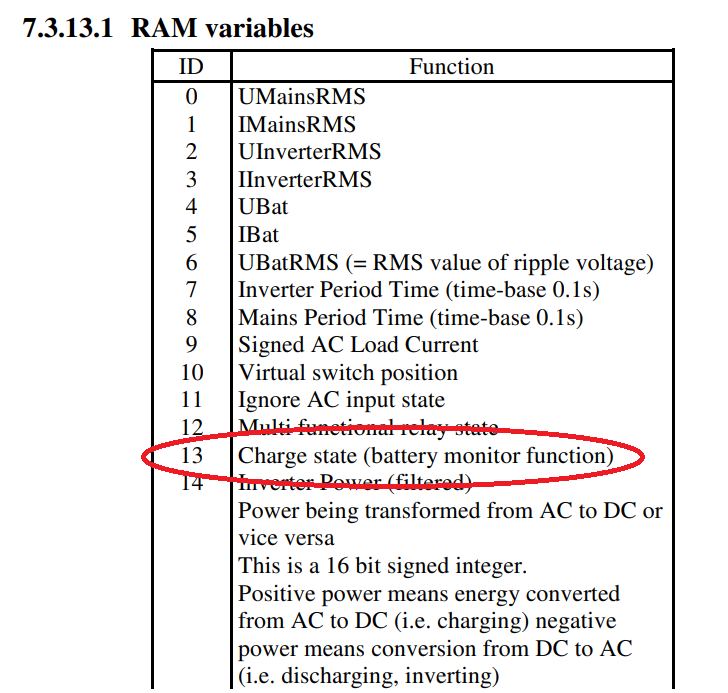
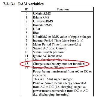
IInverterRMS
4 UBat
5 IBat
6 UBatRMS (= RMS value of ripple voltage)
7 Inverter Period Time (time-base 0.1s)
8 Mains Period Time (time-base 0.1s)
9 Signed AC Load Current
10 Virtual switch position
11 Ignore AC input state
12 Multi functional relay state
13 Charge state (battery monitor function)
14 Inverter Power (filtered)
Power being transformed from AC to DC or vice versa
This is a 16 bit signed integer.
Positive power means energy converted from AC to DC (i.e. charging) negative power means conversion from DC to AC (i.e. discharging, inverting)
Offenbar langsame Drift beim Aufwärmen nach oben; ansonsten 5V = 10cm. Ja, und gleiche Spannung an den Basen ist ziemlich genau Bildschirmmitte.
@Giuseppe Schaltplan in Irfanview geöffnet, Farben von 16 auf 16Millionen (4 auf 3x8bit) erhöht, Zeichendialog geöffnet, Textfunktion gewählt, Farbe rot, Größe 22pixel, bold gewählt und die Zahlen nacheinander eingefügt. Dann auf 44% verkleinert als JPG abgespeichert
close to 99% is removed from the output 1 of the chip 222 and is fed through the resistor R3 to the base of the transistor VT1. A PWM signal with a frequencyfrom0.7 to 4.1 kHz is removed from pin 4 (adjustment by the potentiometer R1) with the possibility of adjusting Figure 5: The multichannel PWM controller
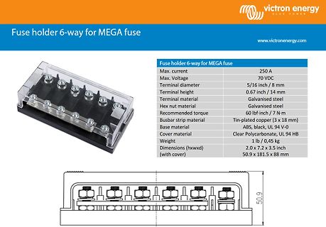
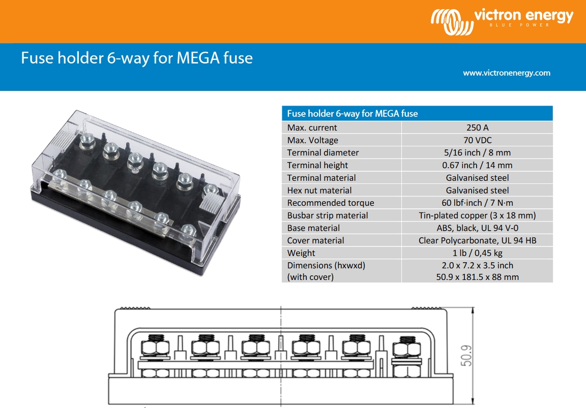
www.victronenergy.com
Fuse holder 6-way for MEGA fuse
Max. current 250 A
Max. Voltage 70 VDC
Terminal diameter 5/16 inch / 8 mm
Terminal height 0.67 inch / 14 mm
Terminal material Galvanised steel
Hex nut material Galvanised steel
Recommended torque 60 lbf-inch / 7 N·m
Busbar strip material Tin-plated copper (3 x 18 mm)
Base material ABS, black, UL 94 V-0
Cover material Clear Polycarbonate, UL 94 HB
Weight 1 lb / 0,45 kg
Dimensions (hxwxd) (with cover) 2.0 x 7.2 x 3.5 inch
50.9 x 181.5 x 88 mm
50.9
user population of about a dozen, most of them friends, and I didn't want to screw up my embedded base. The rest, sadly, is history." https://retrocomputing.stackexchange.com/questions/20292/why-does-make-only-accept-tab-indentation
darin dauern schon etwas. Im ernst? Das kann ich kaum glauben. Hast du schonmal ein make linux -j16 gemacht und gesehen was da abgeht? Die Vorstellung das soetwas banales wie eine Mikrocontrolleranwendung wahrnehmbar lange dauert ist auf aktueller Hardware doch absurd zumal make ja auch dafuer da ist

 Bild
Bild
 Bild
Bild
 Bild
Bild

 Bild
Bild