daher biete ich sie hier zum Verkauf an: SMD Widerstände, alle Größe 0603: Alles zusammen für 20€ zzgl. Versand [code] Wert Anzahl 15R0 380 61R9 362 82R5 363 100R 165 300R 100 1k 327 4k7 182 6k8 267 8k66 310 10k 420 31k6 347 47k 520 100k 617 191k 342 220k 77 470k
384 Stück: 6€ Diode B140, SMA, 431 Stück: 8€ Suppressor Diode SMDJ26CA, SMC, 69 Stück: 8€ Diode BAS70-04, SOT23, 899 Stück: 8€ [/code] Die Teile kommen in verschieden langen Gurtabschnitten und teilweise auf Rollen daher, als Zugabe zu den angegebenen Stückzahlen gibt es immer noch ein paar lose
Jörg aber korrekt beschrieben, denn er bezieht sich auf die meisten Produkte, die in den vergangenen 20 Jahren angeboten wurden.
meinst du genau mit "Outlook"? Hier liest es sich jedenfalls anders: https://keytalk.com/knowledge-base/smime/s-mime-certificates-seem-not-trusted Da steht, die gesamte Kette müsse zugreifbar sein. Dann wird sie wohl auch geprüft werden können und müssen.
Icke ®. schrieb im Beitrag #7745288: > Ja, und in 20 Jahren haben die Windradbürger ~60 Tonnen schwer > recyclebaren Müll wo steht das? Die Dinger werden heute schon zu 100% recycelt. Wobei recycelt hierbei nicht meint, man zerlegt sie in die Einzelteile
Vor 20 Jahren hatte ich mal die Frage gestellt was passiert wenn wir die Sahara vollständig mit Solarpaneels voll pflastern und diese Energie nach Europa per Kabel schicken. Wie wird sich das Klima verschieben
Typical VCOM is only a reference value. It must be optimized according to each LCM. Please use VR and base on below application circuit. Item Symbol Min Typ. Max Unit Remark IG H 3.0 0.2 1.0 mA VG H=16.0V IG L 10.2 0.2 1.0 mA VG L= -7.0V Current for Driver IDV DD 15 4.0 10 mA DV DD =3.3V IAVDD -9.0 20 50
Typical VCOM is only a reference value. It must be optimized according to each LCM. Please use VR and base on below application circuit. Item Symbol Min Typ. Max Unit Remark IG H 3.0 0.2 1.0 mA VG H=16.0V IG L 10.2 0.2 1.0 mA VG L= -7.0V Current for Driver IDV DD 15 4.0 10 mA DV DD =3.3V IAVDD -9.0 20 50
Characteristics (Ta=25˚C) Parameter Symbol Conditions MIN. TYP. MAX. Unit V Input Forward voltage F IF20mA − 1.2 1.4 V Reverse current IR VR=3V − − 100 µA Repetitive peak OFF-state current IDRM VD=V DRM − − 100 µA ON-state voltage V Trms) IT(rms)=2A, Resistance loaF, I =20mA − − 1.5 V Output Holding current
229476.html?term=%2A&sort=relevance&facet=facet.CommonLibraryType&facet.CommonLibraryType=Knowledge%20Base Alle Links zeigen auf cdn.rohde-schwarz.com/hameg-archive/<FILE> und sind heute noch erreichbar, unter den bekannten Firmware-Dateinamen liegt dort aber nichts. Ich nehme an, dass die Firmware-Files
F n 0.1 g t r P.C.B. Mounted on t T = 50 °C v 0.51 x 0.51" (13 x 13 mm) n J A Copper Pads I 0 0.01 20 40 60 80 100 120 140 160 0 20 40 60 8 0 100 Ambient Temperature (°C) Percent of Rated Peak Reverse Voltage (%) Fig. 1 - Derating Curve Output Rectified Current Fig. 4 - Typical Reverse Leakage Characteristics
1000 N A A 25°C T G N TJ= 100°C 25°C N TJ= 100°C R R U R C 100 C100 D C -25°C ,E -25°C , hF F h VCE= 20 V VCE= 20 V 10 10 0.1 1.0 10 100 0.1 1.0 10 100 C , COLLECTOR CURRENT (AMPS) C, COLLECTOR CURRENT (AMPS) Figure 3. DC Current Gain, V = 20 V Figure 4. DC Current Gain, V = 20 V CE CE PNP MJW1302A NPN
=3.~ 5.0【 Note】-5 OH2 - - 100 μ A I 【Note7-1】 3.0V Vcc 3.0V Vcc-turn-on conditions 0.3V data 0 < ≦20ms 0 < ≦50ms t1 t2 t3 0 < ≦1s Vcc Vcc-dip conditions Vcc-dip conditions should also V 0 follow the Vcc-turn-on conditions 2 3 td≦20ms td LCY-99073B-6 【Note7-2】Vcc=3.3V, V/Q= S T Typical current situation
> Nimm ein geeignetes Netzteil. > Du hast 18W Last und dein Netzteil geht erst ab 20W laut Hersteller. Sorry, ich habe mich unklar ausgedrückt. Ich hatte drei verschiedene Netzteile (Maximallast Netzteil 1: 20W, Netzteil 2: 40W, Netzteil 3: 100W). Minimallasten stehen nicht drauf.
Beitrag #7734920: >> Nimm ein geeignetes Netzteil. >> Du hast 18W Last und dein Netzteil geht erst ab 20W laut Hersteller. > > Sorry, ich habe mich unklar ausgedrückt. Ich hatte drei verschiedene > Netzteile (Maximallast Netzteil 1: 20W, Netzteil 2: 40W, Netzteil 3: > 100W). Minimallasten stehen
in any given applicationdepends on the user's specific board design. B. The power dissipatDonP is basJ(MAX)50°C, using ≤ 10s junction-to-ambient thermalresistance. C. Repetitive rating, pulse width limitedby junctioJ(MAX)0°C. Ratings are based on low frequency and duty cycles to keep initiJlT =25°C.
2.70V r BOTTOM2.25VV r BOTTOM2.25VV u u C C c 2.25V c u u 2.25V S 10 S 10 o o - - a a r r , , D D I I 20μs PULSE WIDTH 20μs PULSE WIDTH T = 25 C T = 150 C 1 J 1 J 0.1 1 10 100 0.1 1 10 100 V , Drain-to-Source Voltage (V) V , Drain-to-Source Voltage (V) DS DS Fig 1. Typical Output Characteristics Fig 2.
each MDI trace should be less than 2 inches, or 2000 mils. The traces should be length-matched within 20 mils for 1G transmissions and within 50 mils for 100M or 10M transmissions. The number of vias and stubs on the MDI traces should be kept to a minimum." 50 mil sind 1.27mm, 20 mil sind 0.5mm. Ich
> aufwendig, die Kabel gegeneinander und das komplette Bündel mit Folie + > Geflecht. Das 100BASE-TX um was es hier geht, erfordert entsprechend Norm Cat5 Kabel. Cat5 ist nach der Norm her UTP, Nix Folie, Nix Geflecht. Mit Cat5e gehen auch 1000BASE-T. Die Abschirmung ist aber auch hier ein netter
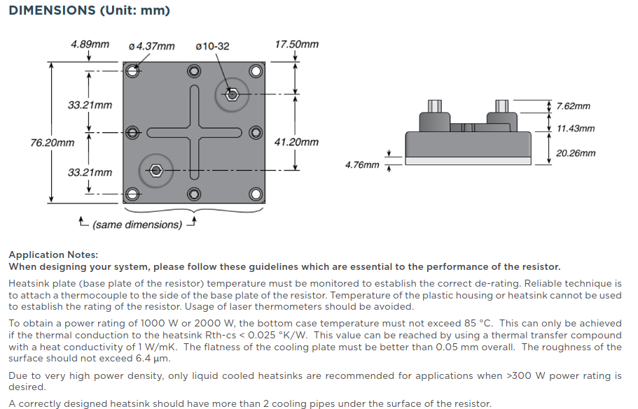
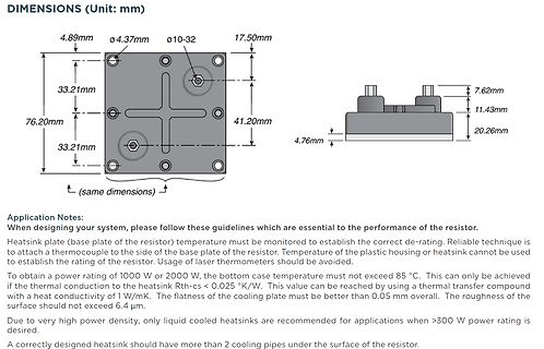
DIMENSIONS (Unit: mm)
4.89mm
ø4.37mm
ø10-32
17.50mm
33.21mm
7.62mm
76.20mm
11.43mm
41.20mm
33.21mm
4.76mm
20.26mm
Application Notes:
When designing your system, please follow these guidelines which are essential to the performance of the resistor.
Heatsink plate (base plate
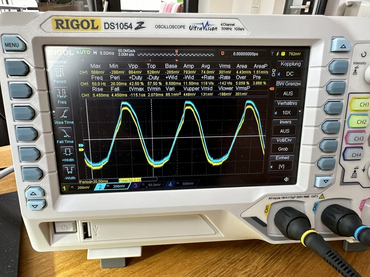
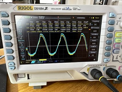
UltraVision 50MHz 1GSa/s MENU AUTO 50.0Ms/s 3.00M pts D 0.0000000ps CH1 568mV -206mV Vpp 528mV -265mV Base Amp 74.0mV 301mV Area 4.43us 1.51ms Kopplung DC Period 20.00ms 50.0Hz 42.50% 57.50% 8.500ms 11.50ms 116V -142V 5.059% 3.866% Rise Fall tvmax tvmin Vupper Vmid Vlower Vrms Vp Rise Time Fall Time +Width
sei denn die Bude brennt. Temperaturänderungen sind i.d.R. langsam. Für Temperaturen sind DS 18B20 genauer https://www.analog.com/en/products/ds18b20.html suche auch DHT22 oder BME280 https://draeger-it.blog/arduino-lektion-44-bme280-temperatur-luftfeuchtigkeit-und-luftdruck-sensor/ während
Karton legt. Dann hat man die nach 1-2h auf sicher 0.5 Grad Temperaturunterschied gebracht (mit DS18B20 und SHT35 gemesssen)
is programmed by accessing a large data- remote starts to flash, and then releasing the buttons. base of product codes on the Internet.The TC 30 is also capable of “learning” codes from your device’s original remote. 23 20 AVR145 harman/kardon INSTALLATION Most of the button labels on the remote describe
import sleep_us po = Pin(0, Pin.OUT, value=0) pi = Pin(3, Pin.IN, pull=None) po.on() sleep_us(20) po.off() sleep_us(100) Pin(3, Pin.OUT, value=0) [/code] Mit dem 30k Widerstand bleibt GPIO 3 nach dem Herunterschalten des Ausgangs bei gut 2V hängen bis ich GPIO 3 als Ausgang auf 0 schalte
.png) 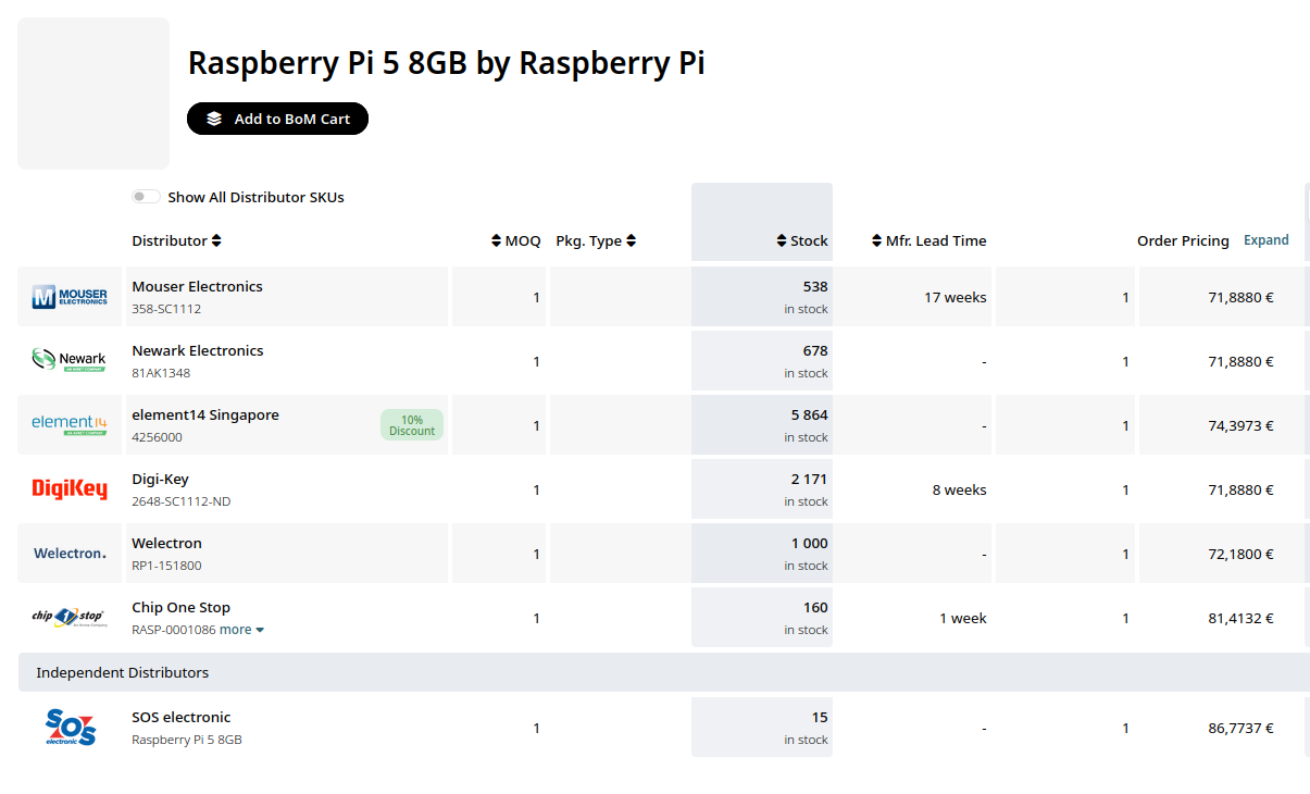 Bildquelle: https://www.oemsecrets.com/compare/RASPberry%20PI%205%23 ### Seeed Studio XIAO auf Basis des vom Arduino Uno R4 bekannten Renesas RA4M1 angekündigt Die Ankündigung des Raspberry Pi RP2350 erfuhren viele Personen dadurch, dass man im Hause Seeed
aufweist und per SCPI mit einem Host kommuniziert: [c] 6½ digit resolution • ±0.2 V, ±2 V, and ±20 V range • Dual channel • 90 days accuracy: <17 ppm of reading range at 2 V range • <0.225 ppm RMS noise of 2 V range at 1 NPLC, 1000 samples • Up to 1 kSPS data rate [/c]
various types of logic. z Package type-APG: DIP-18 pin z Package type-AFG: SOP-18 pin Weight Type Input Base Resistor Designation DIP18-P-300-2.54D: 1.47 g (typ.) SOP18-P-375-1.27 : 0.41 g (typ.) TD62083APG/AFG 2.7 kΩ TTL, 5 V CMOS TD62084APG/AFG 10.5 kΩ 6 V to 15 V PMOS, CMOS Pin Connection (top view) O1
Non-Glare (M-9009A) ° (M-12021NB/M°K12001NB) ° Visual 9" 90 def. Visual 12" 90 def. Visual 12" 90 def. 20mm dia. 20mm dia. 20mm dia. TiltAngle: 10° 10 * Not applicable to Kit 10 ° Type -3- M-900 x: X X Series M-1200 X x X Series COMPOSITE TYPE MODEL ELECTRICAL CHARACTERISTICS 9" M-C9004N M-C9001N 12" M-C12001N
kHz, and SYSCLK = 384 f S unless otherwise noted OUTPUT SPECTRUM FULL-SCALE FFT –60 dBFS FFT 0 0 −20 −20 −40 −40 B B − −60 − −60 e e d d l l p −80 p −80 m m A A −100 −100 −120 −120 −140 −140 0 5 10 15 20 0 5 10 15 20 f − Frequency − kHz G010 f − Frequency − kHz G011 Figure 10. Figure 11. TOTAL HARMONIC
Wenn ich raten müsste, würde ich etwas vermuten, wie ich es vor 20 Jahren (oder so) auch mal installiert hatte: Mehrere TAE-Dosen in der Wohnung, Router und Telefon sollen aber an verschiedenen Orten aufgestellt werden. Dort wo der Router aufgestellt wurde habe
endlos zu diskutieren? Wem soll das was nützen? Meine Anlage oder "Hausinstallation" läuft schon 20 Jahre. Einiges musste nach der Digitalisierung geändert werden, das hat mal ein Telekom-Techniker eingerichtet. Zu behaupten, wie einige es hier tun, "das könne gar nicht funktionieren" und sich hier
es stimmt einfach nicht, eine Verküpfung von H- & V- Sync ist kein Normenwandler und so wird aus BAS oder FBAS Composite kein VGA!
wir ja auf das Thema: der GBS-8200 kann weder PAL, noch NTSC oder SECAM decodieren. Er versteht aber BAS-Signale der o.g. Videonormen, wenn man den Sync entsprechend abtrennt.
ist das mal mit einem IR betrachtet worden während dieser 20min ?
den anderen Bausteinen jeweils gleich? Gibt es überhaupt Signalveränderungen während den toten 20 Minuten? Gibt es beim erneuten Einschalten eine Minuten nach der ersten Totzeit wieder eine 20minütige Totzeit?
Electric Industrial Co., LtTE (16 V, 22 F tantalum type) Transistor: Toshiba Corporation 2SA1213 Base resistance (Rb: 0.68 k Base capacitor (Cb: 2200 pF (Ceramic type) Unless otherwise indicated, connect the recommended components to the IC. When V IN = VOUT(S) 1.2 V (VIN= 2.5 V ______ when V OUT(
RATINGS DESCRIPTION SYMBOL BD433 BD435 BD437 BD439 BD441 UNIT BD434 BD436 BD438 BD440 BD442 Collector Base Voltage V CBO 22 32 45 60 80 V Collector Emitter Voltage V CES 22 32 45 60 80 V Collector Emitter Voltage V CEO 22 32 45 60 80 V Emitter Base Voltage V EBO 5.0 V Collector Current C 4.0 A Collector
water flow/return flow 1 °C / °C Up to 65 / above 18 Up to 65 / above 18 Up to 65 / above 18 Air °C -20 to +35 -20 to +35 -20 to +35 n g 3.2 Temperature spread 9.3 5.0 9.5 5.0 9.4 5.0 l of heating water at A7 / W35 s 2 3 h 3.3 Heat output / COP at A-7 / W35 kW / --- 6.7 / 2.5 6.4 / 2.4 7.7 / 2.4 7.5 /
anhaltend trüben Phasen ist eh der Akku leer und hat erst mal Priorität. Bleiben geschätzt weniger als 20 Tage / Jahr übrig. Wären dann mit den vom TE genannten 2.5kWh/Tag, 20 Tagen/Jahr und 2ct/kWh idealerweise ein satter Euro (1€) pro Jahr an Einsparmöglichkeit. Möglicherweise auch 5€/Jahr, wenn man
der Widerstandswert sich mit der Temperatur nicht linear verhält. Zur Sicherheit rechnen wir mit 20 Ohm. Somit ergibt sich folgendes: Leistung zu diesem Zeitpunkt: 56² / 20 = 156 Watt (Momentanwert!) Stromfluss zu diesem Zeitpunkt: 56 / 20 = 2.8 Ampere (Spitzenwert). Das ist bei Weitem(!
in any given applicationdepends on the user's specific board design. B. The power dissipatDonP is basJ(MAX)50°C, using ≤ 10s junction-to-ambient thermalresistance. C. Repetitive rating, pulse width limitedby junctioJ(MAX)0°C. Ratings are based on low frequency and duty cycles to keep initiJlT =25°C.
data set-up time 250 - 100 [5] - 50 - ns n SU;DAT R o tr rise time of both SDA and SCL signals - 1000 20 300 - 120 ns e e . n tf fall time of both SDA and SCL - 300 20 × 300 20 × 120 [8] ns 6 i [3][6][7][8] [9] — o signals (VDD / 5.5 V) (VDD / 5.5 V) 4 m t set-up time for STOP condition 4.0 - 0.6 - 0.26
PC bzw. RX/TX bool digitalRead (pin) sin (rad) cos (rad) tan (rad) } * mal / geteilt sqrt (x) pow (base, exponent) begin (long speed)//bis 921600Bit/s void loop ( ) { % Modulo (Rest der GZ-Division) digitalWrite (pin, [HIGH, LOW]) int constrain(x, minval, maxval) begin (speed, config) //Config z.B. //
PC bzw. RX/TX bool digitalRead (pin) sin (rad) cos (rad) tan (rad) } * mal / geteilt sqrt (x) pow (base, exponent) begin (long speed)//bis 921600Bit/s void loop ( ) { % Modulo (Rest der GZ-Division) digitalWrite (pin, [HIGH, LOW]) int constrain(x, minval, maxval) begin (speed, config) //Config z.B. //

 Bild
Bild
 Bild
Bild
 Bild
Bild