-
Datei
display_test.c
0x3C,// g 0x7F, 0x08, 0x04, 0x04, 0x78,// h 0x00, 0x44, 0x7D, 0x40, 0x00,// i 0x20, 0x40, 0x44, 0x3D, 0x00,// j 0x00, 0x7F, 0x10, 0x28, 0x44,// k 0x00, 0x41, 0x7F, 0x40, 0x00,// l 0x7C, 0x04, 0x18, 0x04, 0x78,// m 0x7C, 0x08, 0x04, 0x04, 0x78,// n 0x38, 0x44, 0x44, 0x44, 0x38,// o 0x7C, 0x14, 0x14, 0x14, 0x08,// p 0x08, 0x14, 0x14, 0x18, 0x7C,// q 0x7C, 0x08, 0x04, 0x04, 0x08,// r 0x48, 0x54, 0x54, 0x54, 0x20,// s 0x04, 0x3F, 0x44, 0x40,
in „Hilfe bei Nokia 3310 Display“ · Mikrocontroller und Digitale Elektronik ·
-
Datei
Font2.c
Code for char l 0x7C, 0x04, 0x18, 0x04, 0x78, // Code for char m 0x00, 0x7C, 0x04, 0x04, 0x78, // Code for char n 0x38, 0x44, 0x44, 0x44, 0x38, // Code for char o 0xFC, 0x44, 0x44, 0x44, 0x38, // Code for char p 0x38, 0x44, 0x44, 0x44, 0xFC, // Code for char q 0x44, 0x78, 0x44, 0x04, 0x08, // Code for char r 0x08, 0x54, 0x54, 0x54, 0x20, // Code for char s 0x00, 0x04, 0x3E, 0x44, 0x24, // Code for char t 0x00, 0x3C, 0x40, 0x20, 0x7C, // Code for char u 0x1C, 0x20, 0x40
in „Mini-Farbdisplay (+mehr) für 1 Euro“ · Mikrocontroller und Digitale Elektronik ·
-
Datei
font6x8.h
, 0x09, 0x00, // "f" 0x00, 0x18, 0xA4, 0xA4, 0xA4, 0x7C, // "g" 0x00, 0x7F, 0x04, 0x04, 0x78, 0x00, // "h" 0x00, 0x00, 0x00, 0x7D, 0x00, 0x00, // "i" 0x00, 0x40, 0x80, 0x84, 0x7D, 0x00, // "j" 0x00, 0x7F, 0x10, 0x28, 0x44, 0x00, // "k" 0x00, 0x00, 0x00, 0x7F, 0x40, 0x00, // "l" 0x00, 0x7C, 0x04, 0x18, 0x04, 0x78, // "m" 0x00, 0x7C, 0x04, 0x04, 0x78, 0x00, // "n" 0x00, 0x38, 0x44, 0x44, 0x44, 0x38, // "o" 0x00, 0xFC, 0x44, 0x44, 0x44, 0x38, // "p" 0x00, 0x38, 0x44, 0x44, 0x44, 0xFC, // "q" 0x00, 0x44, 0x78, 0x44
in „Displaytech 64128A an ATMega8“ · Mikrocontroller und Digitale Elektronik ·
-
Datei
font6x8.h
, 0x09, 0x00, // "f" 0x00, 0x18, 0xA4, 0xA4, 0xA4, 0x7C, // "g" 0x00, 0x7F, 0x04, 0x04, 0x78, 0x00, // "h" 0x00, 0x00, 0x00, 0x7D, 0x00, 0x00, // "i" 0x00, 0x40, 0x80, 0x84, 0x7D, 0x00, // "j" 0x00, 0x7F, 0x10, 0x28, 0x44, 0x00, // "k" 0x00, 0x00, 0x00, 0x7F, 0x40, 0x00, // "l" 0x00, 0x7C, 0x04, 0x18, 0x04, 0x78, // "m" 0x00, 0x7C, 0x04, 0x04, 0x78, 0x00, // "n" 0x00, 0x38, 0x44, 0x44, 0x44, 0x38, // "o" 0x00, 0xFC, 0x44, 0x44, 0x44, 0x38, // "p" 0x00, 0x38, 0x44, 0x44, 0x44, 0xFC, // "q" 0x00, 0x44, 0x78, 0x44
in „STM32 C was passiert da?“ · Mikrocontroller und Digitale Elektronik ·
-
PDF
plan.pdf
14V V 2 0 C7 C8 TX1 {Cvar} 3 100n C9 R13 C12 1 BAV99 820pF 11.2k 100n D1 0 C10 COUPLING = 0.15 220pF L1_VALUE = 1.78uH L2_VALUE = 1.78uH Q1 Q2N2369 R11 R12 C11 100 1.7k 100n 0 0 0 0
-
Datei
lcdconser.asm
*** Bearbeitung der Parameter *** Next: sbi portd, Busy ;Busy Pin setzen cpi Nextop, SetCurL ;Lade Zeilenadresse brne skipn1 ldi ZeileL, YMin add ZeileL, temp brcs overflow ldi Nextop, SetCurH out sreg, regsave cbi portd, Busy reti overflow: ;Ungültiger Wert: Reset auf Beginn ldi ZeileL, YMin
in „LCD Controller für 640x480 LCD mit mega8515“ · Projekte & Code ·
-
Datei
lcdconser_.asm
*** Bearbeitung der Parameter *** Next: sbi portd, Busy ;Busy Pin setzen cpi Nextop, SetCurL ;Lade Zeilenadresse brne skipn1 ldi ZeileL, YMin add ZeileL, temp brcs overflow ldi Nextop, SetCurH out sreg, regsave cbi portd, Busy reti overflow: ;Ungültiger Wert: Reset auf Beginn ldi ZeileL, YMin
in „LCD Controller für 640x480 LCD mit mega8515“ · Projekte & Code ·
-
Datei
lcdconser640x480.txt
*** Bearbeitung der Parameter *** Next: sbi portd, Busy ;Busy Pin setzen cpi Nextop, SetCurL ;Lade Zeilenadresse brne skipn1 ldi ZeileL, YMin add ZeileL, temp brcs overflow ldi Nextop, SetCurH out sreg, regsave cbi portd, Busy reti overflow: ;Ungültiger Wert: Reset auf Beginn ldi ZeileL, YMin
in „LCD Controller für 640x480 LCD mit mega8515“ · Projekte & Code ·
-
Datei
test_.txt
;.BYTE $A2 ; ;.BYTE $FF ; 801D FF ;umbenannt von 801E 9A TXS ;.BYTE $9A ; 801E 9A ;byte_801C: 801F 78 SEI ;.BYTE $78 ; x 801F 78 ;auf Start_801C: 8020 D8 CLD ;.BYTE $D8 ; Ø 8020 D8 ;CODE XREF: 8021 18 CLC ;.BYTE $18 ; 8021 18 ;ROM:A9A0 A2 ;ROM:loc_A7A7 8022 A9 11 LDA #$11 ;.BYTE $A9 ; © 8022 A9 ;.BYTE
in „Frage an Assembler Programmierer 6502/c02“ · Mikrocontroller und Digitale Elektronik ·
-
PDF
TSR-1_Datenblatt.pdf
@ Vin min. @ Vin max. TSR 1-2412 4.6 – 36 VDC* 1.2 VDC 74 % 62 % TSR 1-2415 4.6 – 36 VDC* 1.5 VDC 78 % 65 % TSR 1-2418 4.6 – 36 VDC* 1.8 VDC 82 % 69 % TSR 1-2425 4.6 – 36 VDC* 2.5 VDC 87 % 75 % TSR 1-2433 4.75 – 36 VDC* 3.3 VDC 1.0 A 91 % 78 % TSR 1-2450 6.5 – 36 VDC* 5.0 VDC 94 % 84 % TSR 1-2465 9.0
in „Idee für ein ||transportables|| Handyladegerät“ · Analoge Elektronik und Schaltungstechnik ·
-
PDF
2450.pdf
@ Vin min. @ Vin max. TSR 1-2412 4.6 – 36 VDC* 1.2 VDC 74 % 62 % TSR 1-2415 4.6 – 36 VDC* 1.5 VDC 78 % 65 % TSR 1-2418 4.6 – 36 VDC* 1.8 VDC 82 % 69 % TSR 1-2425 4.6 – 36 VDC* 2.5 VDC 87 % 75 % TSR 1-2433 4.75 – 36 VDC* 3.3 VDC 1.0 A 91 % 78 % TSR 1-2450 6.5 – 36 VDC* 5.0 VDC 94 % 84 % TSR 1-2465 9.0
in „Power Supply für Raspberry Pi 3b“ · Mikrocontroller und Digitale Elektronik ·
-
 Bild
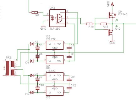
Ausschnitt eines Schaltplans
OK5, R6, 2, 3, 8, 6, 5, TLP 250, VDD, Q9, IRF540, S, R16, R18, Q10, GND, IC3, 78L12Z, 3, VI, + VO, 1, C5, C7, C6, 2, GND, C8, TR2, 10, D2, IC4, 5, D4, 2, VI, VO, 3, D3, C9, IC5, 78L12Z, 3, VI, + VO, 1, C11, C10, 2, GND, C12, D5, 2, VI, VO, 3, IC6
in „Cmos H-Brücken Inverter saugt Quelle leer“ · Analoge Elektronik und Schaltungstechnik · · Schaltpläne
-
PDF
PSMN8R7-80PS_MOSFET.pdf
symbol 1 G gate 2 D drain mb D 3 S source G mb D mounting base; connected to drain mbb076S 1 2 3 SOT78 (TO-220AB) 3. Ordering information Table 3. Ordering information Type number Package Name Description Version PSMN8R7-80PS TO-220AB plastic single-ended package; heatsink mounted; 1 mountinSOT78 hole
in „Motoransteuerung Pi und PWM“ · Mikrocontroller und Digitale Elektronik ·
-
Datei
lcdcon_ft245_4bit.asm
: cpi Nextop, SetCurL ;Lade Zeilenadresse brne skipn1 ldi ZeileL, YMin add ZeileL, temp brcs overflow ldi Nextop, SetCurH ret overflow: ;Ungültiger Wert: Reset auf Beginn ldi ZeileL, YMin ldi Nextop, SetCurH ret skipn1: cpi
in „LCD Controller für 640x480 LCD mit mega8515“ · Projekte & Code ·
-
PDF
ct202011_10.pdf
men App nicht feststellen kann, dass die MichaelGrosenick infiziertePersonderNachbarist,denman l wochenlangnichtgetroffenhat. Es handelt sich vermutlich um Apps, die Ihr t Geräteherstellervorinstallierthat.Einevoll l telyn ständige Liste der installierten Apps liefert l B zum Beispiel der Package
-
Datei
version_1p3_assembler.lst
ON STACK 2386: 0842 D2 11 SETB INPROG ;INTERRUPT IN PROGRESS 2387: ; 2388: 0844 12 05 73 ERL4: CALL L20DPI 2389: 0847 41 F8 AJMP D_L1 ;GET THE LINE NUMBER 2390: ; 2391: 0849 11 F8 I_L: ACALL ISTAT ;LOOP 2392: 084B F1 17 ACALL CLN_UP ;FINISH IT OFF 2393: 084D 50 C4 JNC ILOOP ;LOOP ON THE DRIVER 2394:
in „Basic für 80C31“ · Mikrocontroller und Digitale Elektronik ·
-
Datei
PDM_2SpgE.ino
Arduino Micro * Ausgang OCR1B muss invertiert sein */ #include <util/atomic.h> #define F_PWM 62500L //Hz #define PRESCALER 1 #define TIMER_RELOAD ((F_CPU / ( PRESCALER * F_PWM) -1)) //Fast PWM //Variablen volatile uint16_t Frequenz; volatile uint8_t Amplitude, Amplitude_inv; static uint16_t i; const
in „Arduino Micro SPWM“ · Mikrocontroller und Digitale Elektronik ·
-
PDF
sn74lvc1gx04.pdf
current backflow through the device when it is powered down. FUNCTION TABLE OUTPUTS INPUT X1 X2 Y H L H L H L LOGIC DIAGRAM (POSITIVE LOGIC) 6 Y 3 4 X1 X2 (1) Absolute Maximum Ratings over operating free-air temperature range (unless otherwise noted) MIN MAX UNIT V CC Supply voltage range –0.5 6.5 V
in „Was ist das für ein Chip?“ · Analoge Elektronik und Schaltungstechnik ·
-
PDF
opa128lm.pdf
90 120 dB ±1 ±100 ±1 ±32 ±1 ±32 ±1 ±32 V/V NOISE Voltage: f = 10Hz 92 92 92 92 nV/√Hz O fO= 100Hz 78 78 78 78 nV/√Hz fO= 1kHz 27 27 27 27 nV/√Hz f = 10kHz 15 15 15 15 nV/√Hz O fB= 10Hz to 10kHz 2.4 2.4 2.4 2.4 Vrms fB= 0.1Hz to 10Hz 4 4 4 4 Vp-p Current:Bf = 0.1Hz to 10Hz 4.2 3 2.3 3 fA, p-p fO= 0.1Hz
in „Verkaufe 15 x OPA128LM“ · Markt ·
-
Datei
FFT.asm
+wbH:wbL = waH:waL add @1L, @3L adc @1H, @3H adc @0L, @2L adc @0H, @2H .endmacro .macro cpcw cpc @0L, @1L cpc @0H, @1H .endmacro .macro cpiw cpi @0L, low(@1) ldi rtxdata, high(@1) cpc @0H,rtxdata .endmacro .macro
-
PDF
rd70hvf1c.pdf
Compliance, Silicon MOSFET Power Transistor, 175MHz 70W , 520MHz 50W TEST CIRCUIT(f=175MHz) Vds Vgs L4 22μF 1000pF 8.2kΩ 220μF 1000pF 2200pF L3 8.2kΩ 100pF 1kΩ 56Ω RF_OUT 2.2Ω RD70HVF1C 43pF 39pF 39pF L2 56pF RF_IN L1 LTML 2.2Ω LTML 56pF 2.2Ω 15pF 4pF 4pF 10pF 36pF 82pF 82pF 2.2Ω 56Ω 39pF 29pF 68pF3pF
in „HF Transistoren“ · Analoge Elektronik und Schaltungstechnik ·
-
PDF
RT9080-33GJ5_esp32_8622_low_quiescent_600mA.pdf
Current-Limit Protection Ordering Information Over-Temperature Protection RT9080/N- TSOT-23-5andZQFN-4L1x1(ZDFN-4L1x1) Packages Package Type J5 : TSOT-23-5 Available QZ : ZQFN-4L 1x1 (Z-Type) (ZDFN-4L 1x1) Lead Plating System Applications G : Green (Halogen Free and Pb Free) Portable,BatteryPoweredEquipment
-
PDF
MOS4543_SMD4543_STM.pdf
0.020 B 0.77 1.65 0.030 0.065 b 0.5 0.020 b1 0.25 0.010 D 20 0.787 E 8.5 0.335 e 2.54 0.100 e3 17.78 0.700 F 7.1 0.280 I 5.1 0.201 L 3.3 0.130 Z 1.27 0.050 P001C 8/12 HCC/HCF4543B Ceramic DIP16/1 MECHANICAL DATA mm inch DIM. MIN. TYP. MAX. MIN. TYP. MAX. A 20 0.787 B 7 0.276 D 3.3 0.130 E 0.38 0.015 e3 17.78 0.700 F 2.29 2.79 0.090 0.110 G 0.4 0.55 0.016 0.022 H 1.17 1.52 0.046 0.060 L 0.22 0.31 0.009 0.012 M 0.51 1.27 0.020 0.050 N 10.3 0.406 P 7.8 8.05 0.307 0.317 Q 5.08 0.200 P053D 9/12 HCC/HCF4543B SO16
in „Welcher Treiber zu 7 Segment LED mit Common Anode“ · Mikrocontroller und Digitale Elektronik ·
-
Datei
font.txt
; I .DB 20H, 40H, 41H, 3FH, 01H ; J .DB 7FH, 08H, 14H, 22H, 41H ; K .DB 7FH, 40H, 40H, 40H, 40H ; L .DB 7FH, 02H, 0CH, 02H, 7FH ; M .DB 7FH, 04H, 08H, 10H, 7FH ; N .DB 3EH, 41H, 41H, 41H, 3EH ; O .DB 7FH, 09H, 09H, 09H, 06H ; P .DB 3EH, 41H, 51H, 21H, 5EH ; Q .DB 7FH, 09H, 19H, 29H, 46H ; R .DB 26H
-
PDF
EMS_V2_Plan.pdf
3 7 2 R R R R 330 R19 8 D 1 8 D1 B 1 k 4 1 EMS_TX VIN VOUT EMS_5V C16 5 1N4148SMD B R 5 IC1B R C10 78L05SMD C11 2 k 7 100n R 1 D2 EMS_232_TX 6 330n GND 10n 4 1N4148SMD LM393D T1 2 3 6 7 Q2 BC847 EMS_GND BC857ASMD 5 7 EMS_GND EMS_GND 6 k R 4 R 4 4 0 EMS_GND R 2 RA5 GND k 5 1 + 1 VDD1 VDD2 8 EMS_5V RC7
in „Buderus EMS-"Gateway" mit PIC18F / Sammelbestellung“ · Haus & Smart Home ·
-
PDF
EMS_V2_Schaltplan.pdf
IC6 9 4 B R 5 IC1B R 330 R25 8 D 1 C14 MCLR/ R 7 EMS_TX VIN VOUT EMS_5V t4 3 2 1 EMS_232_TX 6 C12 78L05SMD C13 + C19 4 100n s4 3 2 1 S LM393D T2 e 7 6 k BC847 330n GND 10n 47µ / 50V e ON 2 5 1 9 7 EMS_GND 2 3 6 7 EMS_GND o5 6 7 8 R 4 EMS_GND M R R R EMS_GND GND V 5 1 8 + 2 VDD1 VDD2 7 EMS_5V RC7 3 VOA
in „Buderus EMS-"Gateway" mit PIC18F / Sammelbestellung“ · Haus & Smart Home ·
-
PDF
Schaltplan_PPS_11810.pdf
HDV D1 C7 47pF/1KV C14 NTC BR1 1N5408 220uF S R23 KBU1008 180K/0.5W JNR15S060 M1 250V C5 JVR14N471K L3 HALF 0.68uF 220uH D2 C15 275VAC C6 8ETX06 220uF R24 L2 1uF S 180K/0.5W 400V R14 S 250V R3 R4 5.05mH 240K R26 C21 +/-30% 1% * 10 220pF/250V 270K 270K S Q1 +12V S * S* * S R6 SIHG20N50C R15 S L4 10 240K
in „Voltcraft DPPS 60-10 defekt - Hilfestellung für Instandsetzung benötigt“ · Mikrocontroller und Digitale Elektronik ·
-
PDF
513910-SCHALTPLAN_VOLTCRAFT_PPS_11810.pdf
HDV D1 C7 47pF/1KV C14 NTC BR1 1N5408 220uF S R23 KBU1008 180K/0.5W JNR15S060 M1 250V C5 JVR14N471K L3 HALF 0.68uF 220uH D2 C15 275VAC C6 8ETX06 220uF R24 L2 1uF S 180K/0.5W 400V R14 S 250V R3 R4 5.05mH 240K R26 C21 +/-30% 1% * 10 220pF/250V 270K 270K S Q1 +12V S * S* * S R6 SIHG20N50C R15 S L4 10 240K
in „Ersatztyp für Diode und Mosfet gesucht“ · Analoge Elektronik und Schaltungstechnik ·
-
PDF
513910-SCHALTPLAN_VOLTCRAFT_PPS_11810.pdf
HDV D1 C7 47pF/1KV C14 NTC BR1 1N5408 220uF S R23 KBU1008 180K/0.5W JNR15S060 M1 250V C5 JVR14N471K L3 HALF 0.68uF 220uH D2 C15 275VAC C6 8ETX06 220uF R24 L2 1uF S 180K/0.5W 400V R14 S 250V R3 R4 5.05mH 240K R26 C21 +/-30% 1% * 10 220pF/250V 270K 270K S Q1 +12V S * S* * S R6 SIHG20N50C R15 S L4 10 240K
in „DC Netzteil: 2 FETs durchgebrannt, passiert das einfach so?“ · Analoge Elektronik und Schaltungstechnik ·
-
PDF
513910-SCHALTPLAN_VOLTCRAFT_PPS_11810.pdf
HDV D1 C7 47pF/1KV C14 NTC BR1 1N5408 220uF S R23 KBU1008 180K/0.5W JNR15S060 M1 250V C5 JVR14N471K L3 HALF 0.68uF 220uH D2 C15 275VAC C6 8ETX06 220uF R24 L2 1uF S 180K/0.5W 400V R14 S 250V R3 R4 5.05mH 240K R26 C21 +/-30% 1% * 10 220pF/250V 270K 270K S Q1 +12V S * S* * S R6 SIHG20N50C R15 S L4 10 240K
in „Voltcraft PPS-11810 Schaltnetzteil - Ursache von Fehlverhalten finden“ · Analoge Elektronik und Schaltungstechnik ·
-
PDF
nRF24L01plus.pdf
Adapter, nur HEX Adapter->Server Quickstart Hardwareaufbau https://arduino-info.wikispaces.com/Nrf24L01-2.4GHz-HowTo von der Beschreibung abweichend sind die folgenden Verbindungen: • nRF24L01+ CE → Arduino D8 (ATMega8 PB0) • nRF24L01+ CSN → Arduino D4 (ATMega8 PD4) • nRF24L01+ IRQ → Arduino D3 (ATMega8
in „Repeating und Routing Netzwerk mit Arduino und nRF24L01+“ · Projekte & Code ·
-
PDF
MBI5016.pdf
Datasheet MBI5016 Macroblock 16-bit Constant Current LED Sink Driver Features l 16 constant-current output channels MBI5016CNS l Output current adjustable through an external resistor MBI5016CNS l Serial data in/parallel data out l Output current: 5-90 mA l 20MHz clock frequency
in „Treiber für 12-stellige 7-Segment-LED-Anzeige (ohne Mux!)“ · Mikrocontroller und Digitale Elektronik ·
-
PDF
6N137.pdf
a n 0.390 (9.91) PIN 1 0.370 (9.40) l ID. 4 3 2 1 ID. 1 : 4 3 2 1 N 0.270 (6.86) 1 0.250 (6.35) 0.270 (6.86) 3 5 6 7 8 0.250 (6.35) , H 5 6 7 8 C 0.390 (9.91) P E 0.370 (9.40) L L 0.070 (1.78) 0.070 (1.78) 0.300 (7.62) 2 G 0.045 (1.14) 0.045
in „Optokoppler mit TTL/Schmitt-Trigger?“ · Mikrocontroller und Digitale Elektronik ·
-
PDF
HCPL-263.pdf
a n 0.390 (9.91) PIN 1 0.370 (9.40) l ID. 4 3 2 1 ID. 1 : 4 3 2 1 N 0.270 (6.86) 1 0.250 (6.35) 0.270 (6.86) 3 5 6 7 8 0.250 (6.35) , H 5 6 7 8 C 0.390 (9.91) P E 0.370 (9.40) L L 0.070 (1.78) 0.070 (1.78) 0.300 (7.62) 2 G 0.045 (1.14) 0.045
in „Logic Gate Optocoupler“ · Mikrocontroller und Digitale Elektronik ·
-
PDF
A500_6N137.pdf
a n 0.390 (9.91) PIN 1 0.370 (9.40) l ID. 4 3 2 1 ID. 1 : 4 3 2 1 N 0.270 (6.86) 1 0.250 (6.35) 0.270 (6.86) 3 5 6 7 8 0.250 (6.35) , H 5 6 7 8 C 0.390 (9.91) P E 0.370 (9.40) L L 0.070 (1.78) 0.070 (1.78) 0.300 (7.62) 2 G 0.045 (1.14) 0.045
in „Optokoppler Verstärkung“ · Mikrocontroller und Digitale Elektronik ·
-
PDF
Smartcard-Kode-Schloss_-_Zweites_leben_fuer_Chipkarten.pdf
LEARN high 5 if PIN3 = 0 then learn if PIN3 = 1 then check V+ 5V learn: * IC1 U T K D1 R10 T2 R11 78L05 R R C I for f = 0 to 31 22 22 e = 0 R7 K3 9 7 5 3 1 K1 1N4001 BC557 for g = 0 to 7 4 + C1 C3 C4 e = e * 2 R8 10 8 6 4 2 e = e + PIN4 0 47 k 10 10 63V 1 63V 63V C6 high 6 low 6 220n next g h = 32 *
in „Smartcard-Kode-Schloss mit PIC16F84“ · Mikrocontroller und Digitale Elektronik ·
-
PDF
dvm45_26_Rev1.1.pdf
1 100k 3 C9 V µ R R19 2 8 IC2 6 3 k 7 3 1 ICL7660CPA µ P 3 11µ/35V T 4 C A 15 14 BC337 1 T 1 - C6 78SIC1 0G BC327 k 4 B80C1500/1000 OC7 - I 1E 1 3 4 R TT 7 2 µ 0 Q1 , C 2200µ/25V 1 k 0 B1 0 A 2 , 1 K C A 4 R I 6 , 6 0 8 1 6 J - J µ 6 R 1 R G C 1 S 3 C2 7 1 D1 1 7 S 1 1 4 L ICL8069 J A 1 I I 5,6k - A
in „Projekt DVM 4,5 Digit aus Standardbauteilen mit automatischer Bereichsumschaltung“ · Analoge Elektronik und Schaltungstechnik ·
-
 Bild
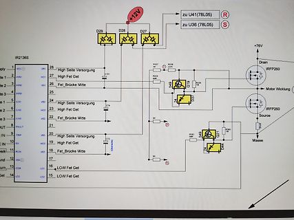
Schaltplan eines Leistungstreiber-Moduls
IR2136S, +12V, zu U41(78L05), R, zu U36(78L05), S, +76V, Drain, IRFP260, Motor Wicklung, Source, Masse, Q19, Q21, D37, D44, 549, 549, 56R, 56R, 15M, 15M, 237k, 237k, R237, R238, R235, R236, 5K, 5K, 5K, High Seite Versorgung,
in „IR2136 Motorendstufe spinnt“ · Analoge Elektronik und Schaltungstechnik · · Fotos
-
PDF
digitast.pdf
Switching Non-shorting Electrical Characteristics Distance Between Horizontal Min.: 12.7 (0.500) or 17.78 (0.700) Switiching Power Max. 240 mW DC Button Centers Vertical Min. 17.78 (0.700) SwitchingVoltage Max. 24 V DC Terminals PC pins Switching Current Max. 10 mA DC Mounting Soldering, centering pins Carrying
in „itt shadow digitast alt?“ · Markt ·
-
PDF
MOS40174_STM.pdf
0.020 B 0.77 1.65 0.030 0.065 b 0.5 0.020 b1 0.25 0.010 D 20 0.787 E 8.5 0.335 e 2.54 0.100 e3 17.78 0.700 F 7.1 0.280 I 5.1 0.201 L 3.3 0.130 Z 1.27 0.050 P001C 8/12 HCC/HCF40174B Ceramic DIP16/1 MECHANICAL DATA mm inch DIM. MIN. TYP. MAX. MIN. TYP. MAX. A 20 0.787 B 7 0.276 D 3.3 0.130 E 0.38 0.015 e3 17.78 0.700 F 2.29 2.79 0.090 0.110 G 0.4 0.55 0.016 0.022 H 1.17 1.52 0.046 0.060 L 0.22 0.31 0.009 0.012 M 0.51 1.27 0.020 0.050 N 10.3 0.406 P 7.8 8.05 0.307 0.317 Q 5.08 0.200 P053D 9/12 HCC/HCF40174B
in „[V] 50St. Latches Philips HEF40174BT SO16 HEX ”D” – TYPE FLIP–FLOP“ · Markt ·
-
PDF
Roland_G-70_Service_Notes_.pdf
8 1 D 9 9 XERES5V XERES5V L7 N2012Z601T02 10 10 D B10B-PH-SM3-TB + GRM39@ D 5 Data Buffers C78 0.1 D +3.3 BD[0..15] GRM39@ BD[0..15] CD[0..31] C73 0.1 3.3V 0 IC27 RA116 5V 2 22 D +3.3 D D 2 IC22 RA50 RA51 IOCT3 9 A8 C B8 11 16
in „Roland G-70 fährt nicht hoch.“ · Analoge Elektronik und Schaltungstechnik ·
-
PDF
Metrawatt-MA_5D.pdf
Spannungsabfiille der Schalttransistoren so aus jdaB am Emitter van V23 die Spannung UK liegt. R55 V23 U3 +S,lV U6 '2.45R49 UK > - - - " V 27" " '- . V78 L eo Nachdem die Ladung beendet ist, beginnt die Digitalanzeige die Taktimpulse zu ztihlen und 81eleheeitis wlrd d'er Kondenntor ex d\.lreh dh. meBberetehubh8
in „S: DMM mit dB-Anzeige“ · Markt ·
-
PDF
Metrawatt-MA_5D.pdf
Spannungsabfiille der Schalttransistoren so aus jdaB am Emitter van V23 die Spannung UK liegt. R55 V23 U3 +S,lV U6 '2.45R49 UK > - - - " V 27" " '- . V78 L eo Nachdem die Ladung beendet ist, beginnt die Digitalanzeige die Taktimpulse zu ztihlen und 81eleheeitis wlrd d'er Kondenntor ex d\.lreh dh. meBberetehubh8
in „Metrawatt MA5D Abgleichanleitung A DC Bereich“ · Analoge Elektronik und Schaltungstechnik ·
-
PDF
hct541.pdf
0.018 b1 0.25 0.010 D 25.4 1.000 E 8.5 0.335 e 2.54 0.100 e3 22.86 0.900 F 7.1 0.280 I 3.93 0.155 L 3.3 0.130 Z 1.34 0.053 P001J 8/12 M54/M74HCT540/541 Ceramic DIP20 MECHANICAL DATA mm inch DIM. MIN. TYP. MAX. MIN. TYP. MAX. A 25 0.984 B 7.8 0.307 D 3.3 0.130 E 0.5 1.78 0.020 0.070 e3 22.86 0.900 F
in „High Voltage Programmer“ · Mikrocontroller und Digitale Elektronik ·
-
PDF
MLCC_stacked_kmt1.pdf
Standard 0.250 Min 1.250 31.75 (6.35) 1.350 34.29 0.070 ± 0.010 1.450 36.83 J J (formed) Standard (1.78 ±0.25) 1.535 38.99 1.950 49.53 0.070 ± 0.010 2.075 52.70 L L (formed) Standard (1.78 ±0.25) 6 © KEMET Electronics Corporation • P.O. Box 5928 • Greenville, SC 29606 (864) 963-6300 • www.kemet.com MIL-PRF
in „Leistungs-Kermikkondensator gesucht“ · Analoge Elektronik und Schaltungstechnik ·
-
PDF
T-3.pdf
TAPING) 416-3113-007 1 Q105 TRANSISTOR(DTA124TS/2SA1589/DTA124TSATP,TAPING)416-KE200S-024 1 IC109 IC(LM78L05 TAPING TO-92) 417-PMSE1-161 1 D.D. MOTOR(198*150mm 94V0) 405-STR880-670B 1 R102,R112 CARBON FILM RESISTOR(150K OHM,1/6W,J,T-26) 412-3113-046 2 R131 CARBON FILM RESISTOR(2.2K OHM,1/6W,J,T-26) 412-3113
in „Eprom von Denon DJ Laufwerk defekt Winbond 78e52“ · Mikrocontroller und Digitale Elektronik ·
-
PDF
Nokia_6100_LCD_Display_Driver.pdf
,0x36,0x33,0x73,0x00, // K 0x78,0x30,0x30,0x30,0x31,0x33,0x7F,0x00, // L 0x63,0x77,0x7F,0x7F,0x6B,0x63,0x63,0x00, // M 0x63,0x73,0x7B,0x6F,0x67,0x63,0x63,0x00, // N 0x3E,0x63,0x63,0x63,0x63,0x63,0x3E,0x00, // O 0x7E,0x33,0x33,0x3E,
in „Alles was man über das Nokia 6100 Display wissen muss“ · Mikrocontroller und Digitale Elektronik ·
-
Datei
lcdcon_ft245_4bit320.asm
;*** Bearbeitung der Parameter *** Next: cpi Nextop, SetCurL ;Lade Zeilenadresse brne skipn1 ldi ZeileL, YMin add ZeileL, temp brcs overflow ldi Nextop, SetCurH ret overflow: ;Ungültiger Wert: Reset auf Beginn ldi ZeileL, YMin ldi Nextop, SetCurH ret skipn1: cpi
in „LCD Controller für 640x480 LCD mit mega8515“ · Projekte & Code ·
-
Datei
lcdcon_ft245_4bit320.asm
;*** Bearbeitung der Parameter *** Next: cpi Nextop, SetCurL ;Lade Zeilenadresse brne skipn1 ldi ZeileL, YMin add ZeileL, temp brcs overflow ldi Nextop, SetCurH ret overflow: ;Ungültiger Wert: Reset auf Beginn ldi ZeileL, YMin ldi Nextop, SetCurH ret skipn1: cpi
in „LCD Controller für 640x480 LCD mit mega8515“ · Projekte & Code ·