/LM10B LM10C Units Min Typ Max Min Typ Max Load regulation 0≤I ≤1.0 mA 0.01 0.1 0.01 0.15 % REF V −VREF≥1.0V (1.1V) 0.15 0.2 % Amplifier gain 0.2V≤VREF≤35V 50 75 25 70 V/mV 23 15 V/mV Feedback sense 195 200 205 190 200 210 mV voltage 194 206 189 211 mV Feedback current 20 50 22 75 nA 65 90 nA
wär's gewesen 😏 Und was ich heraus fand war, gehe ich mit meinen Baumarkt Multimeter, welches auf 200mV Gleichstrom gestellt ist, mit dem schwarzen Kabel (Masse) an Masse der RKL, und gleichzeitig mit dem roten Kabel an die Signalleitung der RKL, dann schaltet diese in einem anderen Blinkmodi. Aber
handelt wäre vorteilhaft. Es handelt sich um folgende RKL -> https://www.amazon.de/dp/B0CSZ5P549?ref=cm_sw_r_apan_dp_4694VEV3ZZK4MF83YCED&ref_=cm_sw_r_apan_dp_4694VEV3ZZK4MF83YCED&social_share=cm_sw_r_apan_dp_4694VEV3ZZK4MF83YCED&starsLeft=1&skipTwisterOG=1 > mMichi S. schrieb im Beitrag #7754206
Typ. Max. Test Condition 1) Junction - soldering poinRthJS – 17 – K/W – 1) For calculationthJAease refer to application note AN077 (Thermal Resistance Calculation) 2.5 2 ] 1.5 W [t t P 1 0.5 0 0 20 40 60 80 100 120 140 160 T S°C] Figure 2 Total Power Dissipation The major part of the IC power dissipation
30 mS time 7.4. Interface Timing Parameters Test Conditions: TA=25℃, VCC=5V, Refer to theAttached Drawing) Name Parameter description Min. Typ. Max. Unit TSSTA Setup time of SDAfalling edge start signa200 nS THSTA Hold time of SDAfalling edge start signal200 nS TSSTO Setup time of SDArising edge stop signal 200 nS THSTO Hold time of SDArising edge stop signal 200 nS TCLOW Low level width of SCLclock signal 200 nS TCHIG High level width of SCLclock signal 200 nS Setup time of SDAinput data to SCLrising TSDA
r 800 TA= 125°C c 90 u u 80 S 700 S i n 70 r 600 a D D 60 t 500 i t 400 a 50 - S 40 S 300 - I D 30 200 VIN = 6.5 V, I 20 VIN= 6.5 V, 100 R ILIM 20 kW R = 200 kW 10 ILIM 0 0 0 100 200 300 400 500 600 700 800 900 1000 VIN- VOUT- 100 mV/div 0 100 200 300 400 500 600 700 800 900 1000 VIN - OUT - 100 mV/div
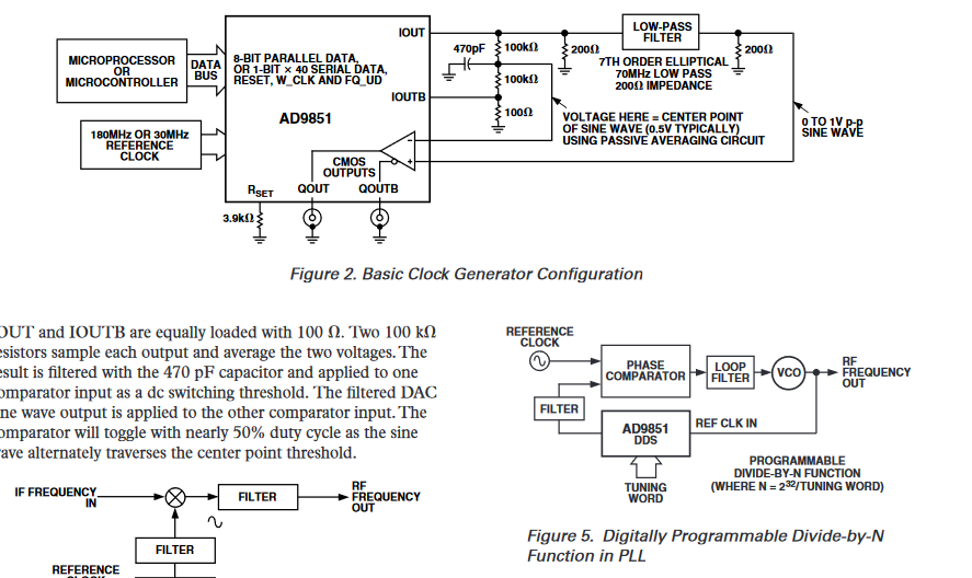
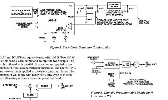
MICROCONTROLLER DATA BUS 8-BIT PARALLEL DATA OR 1-BIT x 40 SERIAL DATA, RESET, W_CLK AND FQ_UD IOUT 470pF 100kΩ 200Ω LOW-PASS FILTER IOUTB 100Ω 200Ω AD9851 CMOS OUTPUTS QOUT QOUTB RSET 3.9kΩ 180MHZ OR 30MHZ REFERENCE CLOCK VOLTAGE HERE = CENTER POINT OF SINE WAVE (0.5V TYPICALLY) USING PASSIVE AVERAGING CIRCUIT 0
Mega 2560 verwendet mit einem RS232 und einem RS485 Adapter. https://www.amazon.de/dp/B07B667STP?ref=ppx_yo2ov_dt_b_fed_asin_title https://www.amazon.de/dp/B09DYDFZRW?ref=ppx_yo2ov_dt_b_fed_asin_title Die 2 Adapter habe ich auf Serial1 und Serial2 angeklemmt. Dann habe ich aus einer Modbus RTU
mit dem > Serial2.readStringUntil(B00001101); habe ich eingebaut, weil die Waage den Wert ca. alle 200ms schickt und ich ohne das "Until(B00001101)" falsche Werte bekommen habe. Ohne hat es nur bis zu einem Intervall von ca. 500ms funktioniert. Float brauch ich eigentlich nicht, es wird kein Komma
For the mapping between INTERRUPT_CORE0_INTR_STATUS_n_REG and peripheral interrupt sources, please refer to Table 8-1. Espressif Systems 200 ESP32-C3 TRM (Version 1.1) Submit Documentation Feedback s 8 r 8.4 Register Summary I s e f r S The addresses in this section are relative to the interrupt matrix
shadow FLASH memory elements fabricated on advanced CMOS technology – Logic densities from 1,600 to 3,200 usable gates (see Table 1) – Combinatorial speeds with t as low as 10 ns PD – Counter frequencies of up to 80 MHz 8 to 16 logic array blocks (LABs) linked by a 100%-connectable programmable interconnect
2013 www.ti.com Typical Applications *Select R3 = V /583μA. V may be any stable positive voltage ≥ 2V REF REF Trim R3 to calibrate Figure 16. Ground Referred Fahrenheit Thermometer Figure 17. Terminating Remote Sensor for Voltage Output *Output impedance of the LM134 at the “R” pin is approximately − where
mal was mit LM334 Stromquelle. Wurde als Temperatursensor Zweckentfremdet. Spannungsreferenz war REF200. Temperaturmessvorsatz für DVM. Weiß jetzt nicht genau wo das war, Elrad, Elektor, PE oder sonst wo. Da konnte man auch mal 20 Meter Kabel dran klemmen. Anbindung ist recht niederohmig. Messfehler
TO interessiert, blättere ich mal die 100 Zeitschriften durch. PS: Habe es gefunden. Nicht REF200 sondern REF02. Ist aus Elektor7-8 1991. Ich stelle das mal hier rein. Ich hoffe kriege keinen ärger. Obwohl 1991...
Dübel, die werden eingeschlagen mit Hammer. https://www.amazon.de/Schlagdübel-40-Nageldübel-Dübel-200/dp/B08RJZWCPP/ref=asc_df_B08RJZWCPP/?tag=googshopde-21&linkCode=df0&hvadid=696184104678&hvpos=&hvnetw=g&hvrand=13140539859840909262&hvpone=&hvptwo=&hvqmt=&hvdev=c&hvdvcmdl=&hvlocint=&hvlocphy=9043528&
REVISED JULY 2022 www.ti.com PARAMETER TEST CONDITIONS MIN TYP MAX UNIT TPS3820 V ≥ V + 0.2 V 112 200 300 ms ttout Watchdog time out DD IT− TPS3823/4/8, TPS3823A See Figure 7-1 0.9 1.6 2.5 s TPS3820 V ≥ V + 0.2 V 15 25 37 td Delay time DD IT− ms TPS3823/4/5/8, TPS3823A See Figure 7-1 120 200 300 MR
legend 2 Mathematica-style formatting 95 For example, if one wanted to plot B·n to the screen with 200 points evaluated to make the graph, the command would be: mo makeplot(2,200) If this plot were to be written to disk as a metafile, the command would be: mo_makeplot(2,200,"c:\\temp\myfile.emf") To write
https://www.amazon.de/Jsdoin-Lichterkette-Lichterketten-Kupferdraht-Batteriebetrieb/dp/B0BLYQGD2Z/ref=mp_s_a_1_1? Die Teile sind der allergrößte Scheiss! Betrieb mit zwei CR2032 Zellen nicht mit Vor- sondern mit Innenwiderstand. Warum man überhaupt bei Amazon kauft, ist mir sowieso schleierhaft.
hab nochmal gemessen. Bei Vin 21V schaltet es hart zwischen irgendwelchen Modi hin- und her, mit 200mA last von der Elast. Siehe output_200mA_19V.png <-> output_200mA_21V. Zwischen den beiden Signalformen ist ein wirklich hartes Umschalten zu sehen. Außerdem hab ich noch eins mit 800mA Ausgangsstrom
Torben H. schrieb im Beitrag #7747031: > Das ist ein 500kHz-Wandler. Das ist ein 200kHz bis 2,2MHz Wandler, den Du mit Deiner Einstellung momentan mit ca. 500kHz betreibst bzw. zu betreiben versuchst, denn richtig funktionieren tut es nicht.
down, right to left DVDD DVDD Down to up, left to right Note 5: Definition of scanning direction. Refer to the figure as below: Note 6: Global reset pin. Active low to enter reset state. Suggest to connect with an RC reset circuit for stability. Normally pull high. Note 7: Dithering function enable control
Outside Dimension 165.0(W)*100.0(H)*3.5(D) mm Active Area 154.21(W)*85.92(H) mm Mechanical Luminance 200 cd/m² Characteristics LED Numbers 21 LEDS - From left to right Pin Order - 50PIN_0.5mm Interface RGB_24bit - Electrical Color Depth 16.7M colors Characteristics HX8282-A11DPD300+HX8696-A01APD300 Driver
AC50Hz S102S02 − − 10 TransferTurn-on time ton T (rms)=2A, Resistance loadF I =20mA ms charac- VD(rms)=200V, AC50Hz teristics S202S02 − − 10 T (rms)=2A, Resistance loadF I =20mA VD(rms)=100V, AC50Hz S102S02 − − 10 Turn-off time t T (rms)=2A, Resistance loadF I =20mA ms off VD(rms)=200V, AC50Hz S202S02 −
, respectively. The response time interval definition is between 10% and 90% of amplitude. Please refer to the figure as below. % Tf Tr 100 90 Optical White Black White response 10 0 G065VN01 V2 Ver. 1.2 7/24 G065VN01 V2 Note 6: Definition of viewing angle 10, at the screen center, over 180° horizontal
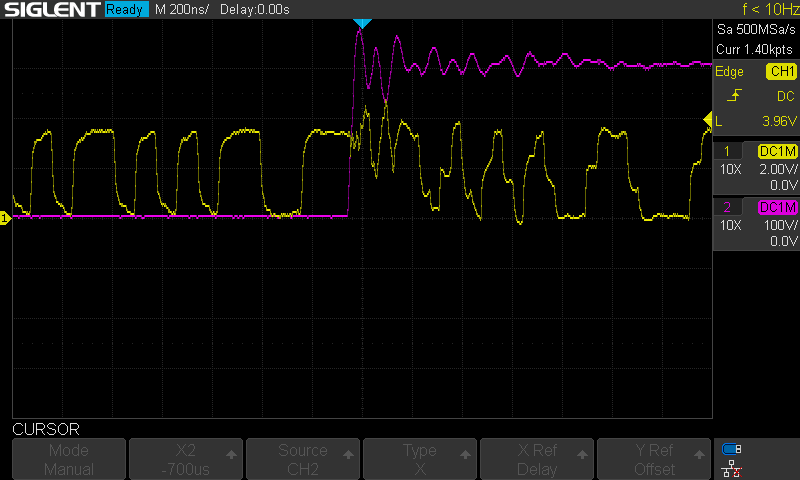
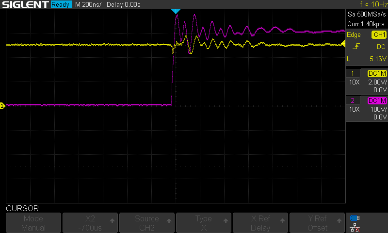
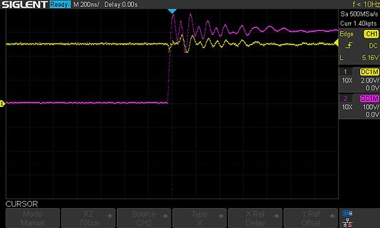
SIGLENT Ready M 200ns/ Delay:0.00s f <= 10Hz Sa 500Msa/s Curr 1.40kpts Edge DC CH1 1 10X 2.00V 0.0V 2 DC1M 10X 100V 0.0V CURSOR Mode Manual X2 -700us Source CH2 Type X X Ref Delay Y Ref Offset
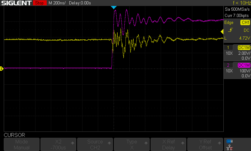
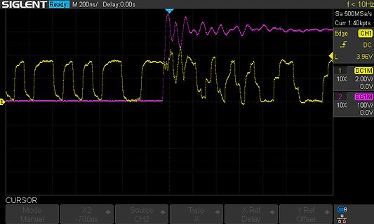
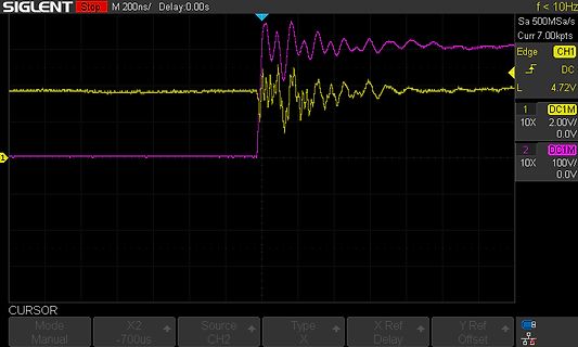
SIGLENT Stop M 200ns/ Delay:0.00s f <= 10Hz Sa 500Msa/s Curr 7.00kpts Edge CH1 DC L 4.72V 1 10X 2.00V 0.0V 2 DC1M 10X 100V 0.0V CURSOR Mode Manual X2 -700us Source CH2 Type X X Ref Delay Y Ref Offset
Description SCL 6 serial clock line SDA 7 serial data line VDD 8 supply voltage 6. Functional description Refer to Figure 1 ÒBloc k diagram of PCA9533Ó . 6.1 Device address Following a START condition, the bus master must output the address of the slave it is accessing. The address of the PCA9533/01 is shown
SET1 = VCC, SET0 = CC Watchdog Disabled Startup Delay Period DELAY SET2 = V CC, SET1 = 0V, VSET0 = 0V 200 600 µs SET2 = V , V = 0V, SET0 = V First Edge (Note 3) CC SET1 CC SET2 = V CC, SET1 = CC , SET0 = 0V First Edge (Note 3) SET2 = V CC, SET1 = CC , SET0 = CC 60 180 s V SET2= 0V, VSET1= 0V, SET0 = 0V
Heilung meiner Geistigen Krankheit? Oder spukt es dort nicht? Getestet wurde im Nachbardorf und in 200 Kilometer Entfernung. Aber vielleicht ist dort auch einfach bessere Luft.
Zimmer und drehst sie auch. Vorher stellst du sie auf AC oder DC auf einen möglichst kleinen Wert (200mA) und schaust dann ob sich der Wert verändert. Je größer die Felder in der Umgebung, desto stärker verändert sich der Wert. Er können Wechselfelder sein oder auch DC-Felder.
AMPERES COMPLEMENTARY Features SILICON POWER TRANSISTORS • Designed for 100 W Audio Frequency 230 VOLTS 200 WATTS • Gain Complementary: Gain Linearity from 100 mA to 7 A hFE = 45 (Min) @ IC= 8 A • Low Harmonic Distortion • High Safe Operation Area − 1 A/100 V @ 1 Second • High fT− 30 MHz Typical 1 • Pb−Free
Sample/Hold Capacitor C — 30 — pF SAR Input Mux Impedance R MUX — 5 — kΩ Voltage Reference Range V REF 1 — VDD V Input Voltage Range V IN Single-Ended (AIN+ - GND) 0 — V REF V Differential (AIN+ - AIN-) -V — V V REF REF Power Supply Rejection Ratio PSRR ADC — 70 — dB DC Performance, VREF = 2.4 V Integral
or 3.3-V parts can communicate with 5-V parts, without any additional protection. External pullup – 200-V Machine model (A115-A) resistors pull the bus up to the desired voltage level – ±1000-V Charged-device model (C101) for each channel. All I/O pins are 5-V tolerant. 2 Applications Device Information
Symbol Test Condition Min. Typ. Max. Unit SCL clock “High” time tHIGH 41 ns SCL clock “Low” time tLOW 200 ns SDA fall time tFDA_OD_L 12.0 ns Bus available condition tAVAL 1 µs Bus idle condition tIDLE 1 ms Push Pull mode Parameter Symbol Test Condition Min. Typ. Max. Unit SCL Clock Frequency SCL 0.01 12.5
which are not Wavecom owned. 1.1.1 Open AT ® Software Documentation [1] Getting started with Open AT (Ref.WM_ASW_OAT_CTI_001) ® [2] Open AT Tutorial (Ref.WM_ASW_OAT_UGD_001) [3] Tools Manual (Ref. WM_ASW_OAT_UGD_003) [4] Open AT Basic Development Guide (Ref. WM_ASW_OAT_UGD_002) [5] Open AT ADL guide (Ref. WM_ASW_OAT_UGD_006) ® [6] Open AT Customer Release Note (Ref. WM_ASW_OAT_DVD_00062) 1.1.2 AT Software Documentation [7] AT commands interface Guide for X51 (Ref. WM_ASW_OAT_UGD_00016) [8] Customer Release Note X51 (Ref. WM_ASW_OAT_DVD_00120) 1.1.3 Other Documents
Time 3 – 45 400 ns VDD = 12 V, RL = 820 Ω, CL = 20 pF RthJSB Thermal Resistance Junction to – 150 200 K/W Fiberglass Substrate case Substrate Backside 30 mm x 10 mm x 1.5 mm, SOT89B-2 pad size see Fig. 3–6 RthJS Thermal Resistance – 150 200 K/W case Junction to Soldering Point TO92UA-3, TO92UA-4 1.80
rss gd ( C oss= Cds + Cgd e 8 ) t p o ( 800 C iss V c c 6 a u c 600 o a - a - 4 , t C 400 a , S 2 200 VG Coss C 0 rss 0 1 10 100 0 4 8 12 16 V DS , Drain-to-Source Voltage (V) Q G Total Gate Charge (nC) Fig 5. Typical Capacitance Vs. Fig 6. Typical Gate Charge Vs. Drain-to-Source Voltage Gate-to-Source
on page 34. • Refer to Wiring Requirements and Recommendation on page 39. 0xF017 Non- An unexpected software error occurred due to Perform one of the following: recoverable unexpected hardware interrupt. • See Corrective
OPP TNVP Timing for Negative Voltage Protection 3.3 7.0 10.2 Ms Shunt Regulator Section Current V REF Reference Voltage FB=0.5mA, T A25°C 2.475 2.500 2.525 V VDEV, I Deviation of VREFOver FB Current (4) FB=0.5mA to 10mA 20 mV (4) VDEV, T Deviation of VREFOver Temperature 10 30 mV (4) R EGLI-FB Line
B59771C0120A070 C772 43 86 2.8 2.5 150 96 X X B59772C0120A070 Vmax= 440 V DC or V AC,RV = 400 V DC or V AC,ref= 130 °C (typ.R, R = ±25 % C1412 75 150 7.0 6.0 120 63 ▯ ▯ B59412C1130B070 C1451 100 200 12.0 7.0 56 29 ▯ ▯ B59451C1130B070 Vmax= 550 V DC or V AC,RV = 500 V DC or V AC,ref= 115 °C (typ.R, R = ±25 %
20Hz–20kHz into 8 ohms Input Sensitivity/Impedance Power Requirement AC 120V/60Hz Linear (High-Level) 200mV/47k ohms Power Consumption 65W idle, 540W maximum (5 channels driven) Signal-to-Noise Ratio (IHF-A) 100dB Dimensions (Product) (Shipping) Surround System Adjacent Channel Separation Width 17-5/16
viel Gas und auch sehr unruhig. Es kommt eine unruhige Flamme .... Gas hab ich von Kontakt Chemie REF BUTANE Weiß jemand, was da falsch läuft ? Ein Gerät ist fast neu, und das andere ist etwas ältere, aber beides verhalten sich gleich! Besten Dank
leer oder voll der Tank war - es funktionierte immer zuverlässig. Ersa 130 kostet 100€, Weller über 200€ ;) Ich hab den Weller mehr oder weniger zerlegt - hat jemand evtl. die Grundeinstellung für den silbernen Regler ? Danke vielmals
und nicht im Gerät > eingestellt sind. Genau deswegen; Alles sofort auf den Tisch und nicht in 200 Threads verteilt, schon fluppt es.
Esmu P. schrieb im Beitrag #7727310: > Genau deswegen; Alles sofort auf den Tisch und nicht in 200 Threads > verteilt, schon fluppt es. Um welche anderen 199 Threads geht es noch? Ich dachte, der hier wäre schon genug ... BTW: Wurde denn nun endlich mal das Ref-Gnd mit an den Moxa angeschlossen
folgende Komponenten gekauft und angeschlossen. Potentiometer: https://www.amazon.de/dp/B09YRDTRTV?ref=ppx_yo2ov_dt_b_fed_asin_title&th=1 TRU Components Drehzahl- und Leistungsregler: https://www.amazon.de/dp/B0767KKLKQ?ref=ppx_yo2ov_dt_b_fed_asin_title Rohrlüfter: https://www.ebay.de/itm/375090849208
- und Leistungsregler 1570778 230 V/AC 15A 200W Verpackungsgröße: Inhalt: 1 Stück Originalqualität von TRU Components"
rechnen. Die entsprechende Funktionen sind tfestimate oder etfe. https://de.mathworks.com/help/signal/ref/tfestimate.html https://de.mathworks.com/help/ident/ref/etfe.html Mithilfe der Funktion pwelch kannst du das Leistungsdichtespektrum des Grundrauschens deiner Messkanäle und deines Anregungskanals
. 200mA an 0,58 R ergeben ungefähr 1.1V rms / 1.6V pk. Damit werden von den 16Bit Auflösung nur noch ca. 13 Bit genutzt. Genauigkeit (nicht auflösung) geschätzt auf 11..12 Bit. ergo: Einsatz eines Vorverstärker

 Bild
Bild
 Bild
Bild
 Bild
Bild
 Bild
Bild
 Bild
Bild