LED1 U1 Table of Contents KSZ8851SNL r 2.25" Page 1: Revision History & Block Diagram e Page 2: KSZ8851SNL 32-pin Ethernet Controller Chip RJ-45 T d a e H Crystal 6 / LED33 4 U4 (MIC5209YM) J (MIC5209YM) A A 3.75" MICREL SEMICONDUCTOR Title KSZ8851SNL DEMO BOARD Size Document Number Rev
auf einer Seite zu einem ähnlichen Board: https://onlinedocs.microchip.com/pr/GUID-FC2A0384-AC9D-45B4-951E-5C0DEFE8B2E9-en-US-5/index.html?GUID-E45ECAF4-48D5-4D67-BE87-4DF8AE01358D Habe das dort aufgeführte Kommando ausgeführt (siehe Screenshot), was erstmal erfolgversprechend schien; allerdings wird
Anscheinend ist das Verifizieren der geschriebenen Fuses > fehlgeschlagen. Hab das gleiche Problem mit SAM4E16E & SAMC21. Egal ob mit SEGGER SAM-ICE oder ATMEL-ICE Programmer. Klickst du "Program" scheint alles gut zu sein, klickst du dann "Verify" kommt deine Fehlermeldung. Nutzt du jedoch die JLink.exe
Transceiver height, front, that extends inside cage ± 0.1 C 8.5 ± 0.1 Transceiver height, rear D 13.4 ± 0.1 Transceiver width, rear E 1.0 Maximum Extension of front sides outside of cage, see Note 2 Figure 1B F 2.3 Reference Location of cage grounding springs from centerline, top G 4.2 Reference Location
posi- locations distance of component tion. Even product diversity and a Paper and 2 x 8 mm S 1 2 or 4 mm 2.5 mm small batch sizes can be handled blister tapes 3 x 8 mm S 1 2 or 4 mm 2.5 mm easily since the feeder set-up can 3 x 8 mm S b 1 2 mm 0.7 mm be changed quickly. 12/16 mm S 1 4 - 12 mm c 14 mm
must fit in a uint16_t variable // i.e.: noOfPulses x pulseLenth < 65536 volatile uint16_t pulse_width; // volatile variable for ISR routine volatile bool isFinished; // volatile variable for ISR routine uint16_t maxTicks
-01 Ph:BT138X-800 Same Product Available in SOT186A (isolated package). Consult Marketing. BT138F-800E 4 QUADRANT TRIAC 934027120127 T M 3 31-12-00 30-6-01 Ph:BT138X-800E Same Product Available in SOT186A (isolated package
Poynting-Vektor betrachtest und wie er sich bei Reflexion verhält. Und was das für das Kreuzprodukt E x H bedeutet.
her? http://www.zeno.org/Literatur/M/Tucholsky,+Kurt/Werke/1928/Wo+kommen+die+L%C3%B6cher+im+K%C3%A4se+her+-%EF%BC%9F?e Um beim Haareschneiden meinen Hinterkopf zu betrachten habe ich einen zweiten Spiegel an der Badezimmertür angebracht, der im anderen Spiegel zu sehen ist. Also wie oben der Corner-Reflektor
power output terminal (24 VDC output). Azimuth motor drive power output terminal (24 VDC output). 4 4 O P E R A T IO N 4 -1 Start and Stop Press the POWER switch. The POWER indicator (green) lights. Stop The POWER indicator (green) turns off. 4 -2 Selection of Satellite (RUN MODE) Data on the elevation
US G6B-1174P-FD-US G6B-2014P-US 1,000 1,000 )200 G n n ( 6 t500 G6B-1114P-US t500 G6B-2114P(-FD)-US e e 250 VAC/30 VDC resistive load e G6B-2214P(-FD)-US t180 B p300 p300 G6B-2014P(-FD)-US o G6B-1114P-US 4o G6B-1174P-FD-US 4o 250 VAC/30 VDC inductive load i G6B-1174P-US 1 1 (cosφ = 0.4, L/R = 7 ms) c
MOSFET ja, aber du verwendest einen bipolaren Transistor. Hans E. schrieb im Beitrag #7668905: > Nur noch 4Volt am Relais? > Ich bin davon ausgegangen das bei einem Basiswiderstand von 1,2K der > Transistor übersteuert. Ja schon, aber nicht in dieser Schaltung
falsch gepolt war. Auch ist es einfacher, wenn man Teilsymbole zum besseren Routen vertauschen will (4-fach OPV, Gatter usw.). Große Schaltungen kann man nachträglich verkleinern, indem man Blöcke markiert und per Drag-Funktion zusammen schiebt (Altium: e,m,r). Das PDF-Format ist schon länger zur
Projekterstellung und compilieren geht. Aber Debuggen stürzt ab. [Failed to launch GDB: Truncated register 16 in remote 'g' packet (from target-select extended-remote localhost:50000)] Sagt mir nix und weiß auch nicht wie zu fixen. In der Doku (Starting with Pico) ist dazu nichts zu finden. In der vorherigen
und Python ist neueste installiert. siehe auch: https://github.com/raspberrypi/pico-vscode/issues/16 was meinen ursprünglichen Fehler behandelt. Gruß Rudi
werden. https://onlinedocs.microchip.com/pr/GUID-671CAF55-DB13-4D9A-8881-F58C984111B5-en-US-4/index.html?GUID-23D41E7C-F770-49A0-9365-D13987945F29 Alte Version von MPLAB X: https://ww1.microchip.com/downloads/en/DeviceDoc/MPLABX-v5.30-windows-installer.exe
...............00.07.19 Script build number...........343401fe73 Tool pack version ............2.4.1239 Target device ATmega328P found. Device Id Revision = 0x0 (A) Device Id = 0x1e950f The following memory area(s) will be read: configuration memory Read complete
ELECHOUSE_cc1101.setSyncMode(2); // Combined sync-word qualifier mode. 0 = No preamble/sync. 1 = 16 sync word bits detected. 2 = 16/16 sync word bits detected. 3 = 30/32 sync word bits detected. 4 = No preamble/sync, carrier-sense above threshold. 5 = 15/16 + carrier-sense above threshold. 6 = 16/16
was falsch mache? Zur Interpretation der Screenshots: Das was man unter "hex decode" sieht sind 4 Byte preamble AAAA, dann 4 Byte Syncword d391, dann die Länge 0b und dann die ASCII-Hexwerte von H,e,l,l,o, ... Man sieht oben das AM demodulierte Signal und unten das FM demodulierte Signal. Es sind
B59451C1130B070 Vmax= 550 V DC or V AC,RV = 500 V DC or V AC,ref= 115 °C (typ.R, R = ±25 % C755 28 55 1.4 2.0 500 230 X X B59755C0115A070 C774 16 32 1.0 1.5 1100 700 X X B59774C0115A070 Vmax= 550 V DC or V AC,RV = 500 V DC or V AC,ref= 120 °C (typ.R, R = ±25 % C773 24 48 1.0 2.0 500 320 X X B59773C0120A070
controller. Position form implementation of // a digital PID. See SpeedControl subroutine for details SFRAC16 Kp = SFloat_To_SFrac16(0.1); // P Gain //0,1 SFRAC16 Ki = SFloat_To_SFrac16(0.01); // I Gain //0,01 SFRAC16 Kd = SFloat_To_SFrac16(0.000); // D Gain //0,000 // Constants used by the PID controller, since a MAC operation is used, the // PID structure is changed (See SpeedControl() Comments) SFRAC16 ControlDifference[3] \ __attribute__((__space__(xmemory), __aligned__(4))); SFRAC16 PIDCoefficients[3] \ __attribute__((__space__(ymemory), __aligned__(4))); // Used as a temporal variable to perform
, i.e. 0-255 for a full circle 2,3 Compass Bearing as a word, i.e. 0-3599 for a full circle, representing 0-359.9 degrees. 4 Pitch angle - signed byte giving angle in degrees from the horizontal plane 5 Roll
DesignCon 2003 TecForum I C Bus Overview 115 LCD Segment Control Display s1 x 24 … 2 x 40… single chip: 4 x 40 ... 16 x 24 Slide 115 Control logic SDA The PCD3311C and PCD3312C are single-chip silicon SCL RAM e gate CMOS integrated circuits. They are intended d e a principally for use in telephone sets to
precursor data and combining physics-of-failure models to predict the used in automotive circuits (e.g., the protection of micromotors remaining useful life (RUL) of PPTC resettable fuses. in window lifts, seats, and door locks), computers (e.g., the protection of the circuits in hard disk drives, interface
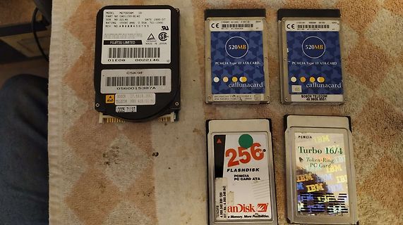
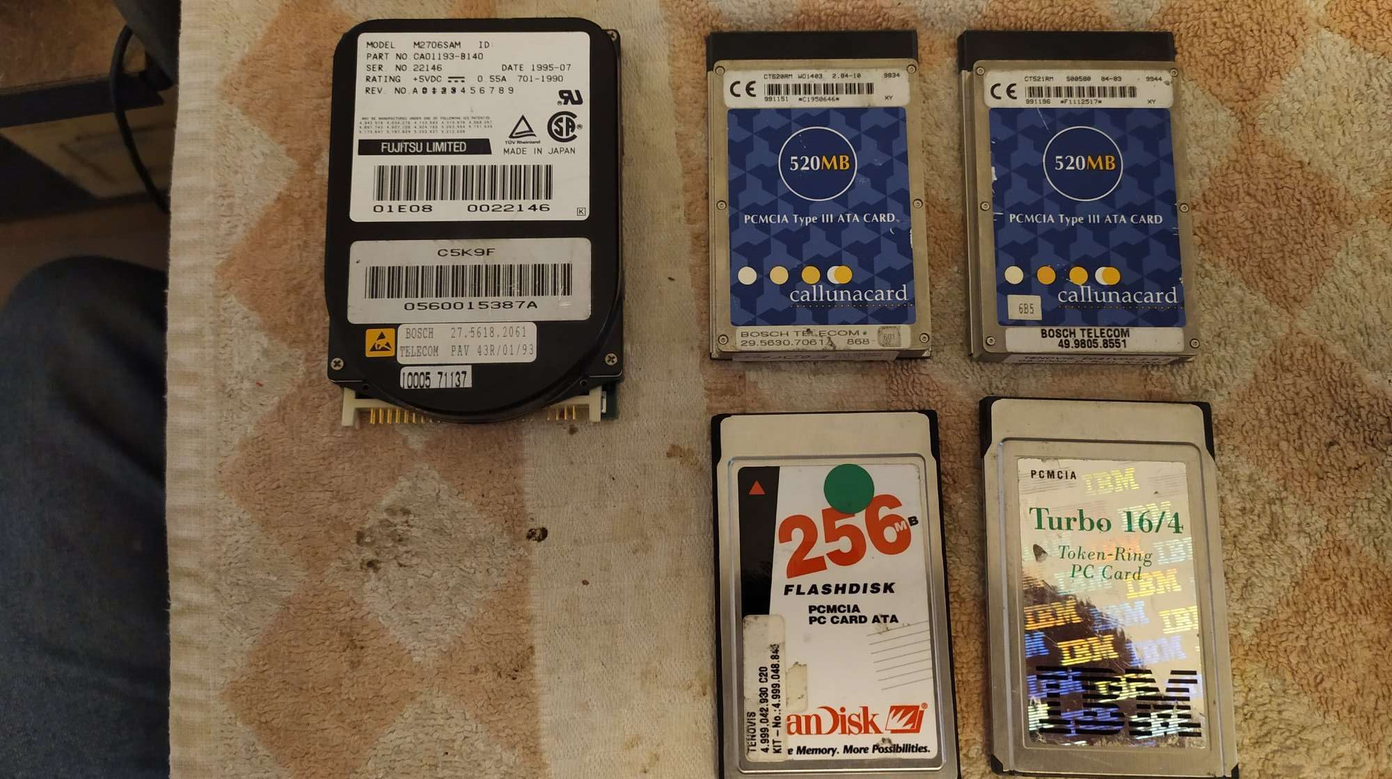
MODEL M2706SAM ID
PART NO CA01193-B140
SER NO 22148
RATING +5VDC 0.55A 701-1990
REV NO A 0 1 2 3 4 5 6 7 8 9
FUJITSU LIMITED MADE IN JAPAN
01E08 0022146
520MB PCMCIA Type III ATA CARD
callunacard
BOSCH TELECOM
29.5630.7051
habe ich angesetzt und diesen Zweig von der Ausgabe getrennt und verwende nun den internen DAC vom SAM4E16E und schleuse das Signal so ein, funktioniert! Nun habe ich bis jetzt meine EKG Signale selbst mit Excel designt, was jedoch ziemlich umständlich ist (siehe Bild_1). Die DAC Werte werden dann
3.8 - - V R R Reverse current at VR= 3.8 V IR - - 100 μA Reverse breakdown voltage atRI = 1 mA V BR 4.5 5.3 6.2 V at PP= 1 A - 7 8.4 V Reverse clamping voltage VC at PP = PPM = 30 A - 14 16.8 V Capacitance at VR= 0 V; f = 1 MHz C - 210 300 pF at VR= 1.6 V; f = 1 MHz D - 190 - pF Rev. 2.6, 02-May-17 8
DC *V electrical Max. switching current 6 A Constant current Ith2 6 A Constant current Ith2at the same time over 2 contacts 4,2 A Constant current Ith2at the same time over 3 contacts 3,4 A Switching capacity NO-contact/NC-contact AC-15 230/240 V le=4/1,2 A NO-contact/NC-contact DC-13 24 V le=2/1,2 A
TSSOP24 D A L terminal 1 A A A V S CS index area 2 2 2 2 2 1 LED0 1 18 RESET LED1 2 17 LED15 LED2 3 16 LED14 PCA9532BS LED3 4 15 LED13 LED4 5 14 LED12 LED5 6 13 LED11 7 8 9 1 1 1 6 7 S 8 9 1 E DE V E DE D 002aae520 L L L L L Transparent top view Fig 4. Pin configuration for HVQFN24 PCA9532 All information
wiki: The eZ80 (like the Z380) is binary compatible with the Z80 and Z180, but almost three times as fast as the original Z80 chip at the same clock frequency.
NO WARRANTY; for details see the file "COPYING" in the distribution directory. RAM: 1024 KByte, 4 KByte YAZEPAGESIZE, 256 PAGES MMU: 16 TABLES, 16 PAGEPOINTERS per TABLE, selected MMU-PAGETABLE: T00 Running '/usr/local/lib/yaze/yaze-cpm3.boot' BOOTSYS - CPM3.SYS, V 1.30 16.01.2015 (c) 2000,2015
. // Constructor - for OLED display library - see u8g2 documentation U8G2_SSD1309_128X64_NONAME0_F_4W_HW_SPI u8g2(U8G2_R0, 10, 9, 7); volatile uint16_t pulse_width; volatile bool isFinished; char buffer[32]; uint16_t min; uint16_t max; uint8_t noOfPulses = 80; // number of pulses to use for a measurement. Do not choose // to large values as sum of all pulseLength must fit in a uint16_t variable // i.e.: noOfPulses x pulseLenth < 65536 void setup() { pinMode(pin, INPUT); pinMode(pout, OUTPUT); u8g2.begin(); // start the u8g2 library u8g2.setBitmapMode(1); u8g2.setFont(u8g2_font_helvB08
...................................................................................................16 T F T info@panadisplay.com Page 2 of 16 www.panadisplay.com PS817-070WS-C-IPS-46 1. Module Classification Information t PS HDMI 070 W C T e 1 2 3 4 5 6 e No. PARAMETER SYMBOL h 1 Brand PS - PANADISPLAY
operational. To assure a noise margin, the MOS-FET’s should have a minimum threshold voltage V of e.g. 0.4V and VDD1 must stay below this value. The isolation feature can also be applied if no level shifting is required, VDD1 and VDD2 may have the same value, e.g. both 3.3V or both 5V. 11 Philips Semiconductors
EXPONENT 0 + / - LOCATION 1 IEEE-488 INTERFACE 1 1 O O1 1 01 1 O S A T T L L S R P D C E A2A1 A3 A4 DIGITAL I/O EXTERNAL TRIGGER SENSING INPUT LOCAL OUTPUT REMOTE LINE RATING FUSE 50-60 Hz AC, 80 VA MAX LINE VOLTAGE SELECTED 90-110V 180-220V 105-125V 210-250V SLOWBLOW 3/4A 90-125V MADE IN
-Taping specification for axial capacitors Description Symbol Dimensions (mm) Capacitor diameter D 4,5÷ 19,5 Capacitor length L 10,5÷ 32,0 Component pitch A* Seetable I Reel core diameter E 60 Arbor core diameter M 16 Reel diameter ø 340+5 Marking F Seetable II Tape width H 6±0,5 Body location (lateral

 Bild
Bild